Mannesmann Rexroth A10VO 25 DFR Setup guide

Reparaturanleitung - A10VO 25 DFR Baureihe 52
A10VNO 41-85 DFR Baureihe 52
Repair instructions - A10VO 25 DFR Series 52
A10VNO 41-85 DFR Series 52
RDE92703-02-R/12.00

Reparaturanleitung A10V(N)O
Repair Instructions A10V(N)O
RDE 92703-02-R/12.00
2 Brueninghaus Hydromatik
NOTICE
Specifications, descriptions and illustrative material shown
herein were as accurate as known at the time this
publication was approved for printing.
For repair, please use only original spare parts.
Optional equipment and accessories may add cost to the
basic unit, and some options are available only in
combination with certain models or other options.
For the available combinations refer to the relevant data
sheet for the basic unit and the desired option.
Adjustment and tests have to be carried out on the test
bench under operating temperatures.
Protection of personnel and property has to be guar-
anteed by appropriate measures.
Expert knowledge, the precondition of any service work,
can be obtained in our training courses.
CONTENTS
A10V(N)O
Sectional view
General repair guidelines
Sealing the drive shaft
Sealing / cleaning the control valve
Disassemble the pump
Remove rotary group
Remove control device
Remove shaft / beaerings
Inspection hints
Pump assembly
Adjustment of taper roller bearing
Pump assembly
Control valve: Guidelines for the DR, DFR, DFR 1
Tools, auxiliary tools, tightening torques
HINWEIS
Bezeichnungen, Beschreibungen und Darstellungen
entsprechen dem Informationsstand zum Zeitpunkt der
Drucklegung dieser Unterlage.
Änderungen können den Service am Produkt beein-
flussen, Verpflichtungen entstehen uns daraus nicht.
Methoden und Vorrichtungen sind Empfehlungen, für
deren Resultat wir keine Haftung übernehmen können.
Reparaturen nur mit Original-Ersatzteilen durchführen.
Einstell- und Prüfarbeiten sind bei Betriebstemperatur auf
dem Teststand vorzunehmen.
Schutz von Personen und Eigentum ist durch Vor-
kehrungen sicherzustellen.
Sachkenntnis, die Voraussetzung für jede Servicearbeit,
vermitteln wir in unseren Schulungskursen.
INHALT Seite/
Page
A10V(N)O
Schnittbild 3
Allgemeine Reparaturhinweise 4
Triebwelle abdichten 5-6
Steuerventil abdichten / reinigen 7
Pumpe demontieren 8-10
Triebwerk ausbauen 11
Stellsystem ausbauen 12
Welle / Lager ausbauen 13
Überprüfungshinweise 14-15
Pumpe montieren 16-17
Abstimmung Lagerung 18
Pumpe montieren 19-24
Steuerventil: Hinweise für DR, DFR, DFR 1 25
Werkzeuge / Hilfswerkzeuge / Anziehdrehmomente 26
Hinweis / Inhalt
Notice / Contents

RDE 92703-02-R/12.00
Reparaturanleitung A10V(N)O
Repair Instructions A10V(N)O
Brueninghaus Hydromatik 3
Schnittbild
Sectional view
NG 41-85
Verschlußschraube OHNE Ringnut
Size 41-85
Plug WITHOUT groove
NG 25
Verschlußschraube MIT Ringnut
Size 25
Plug WITH groove

Reparaturanleitung A10V(N)O
Repair Instructions A10V(N)O
RDE 92703-02-R/12.00
4 Brueninghaus Hydromatik
Allgemeine Reparaturhinweise
General repair guidelines
Achtung!
Nachfolgend Hinweise bei allen Reparaturarbeiten
an Hydraulikaggregaten beachten!
Attention!
Observe the following guidelines when carrying out repairs
on hydraulic units!
Alle Öffnungen der Hydraulikaggregate verschließen.
Close off all openings of the hydraulic unit.
Alle Dichtungen erneuern.
Nur original BRUENINGHAUS HYDROMATIK
Ersatzteile verwenden.
Replace all of the seals.
Use only original BRUENINGHAUS HYDROMATIK
spare parts.
Alle Dicht- und Gleitflächen auf Verschleiß prüfen.
Achtung: Nacharbeiten an Dichtflächen z.B. durch
Schleifpapier kann die Oberfläche beschädigen.
Check all sealing and sliding surfaces for wear.
Attention: Re-work of the sliding surfaces by using, for
example abrasive paper, can damage the surface.
Hydraulikaggregate vor Inbetriebnahme mit
Hydrauliköl befüllen.
Fill the hydraulic unit with hydraulic oil
before commissioning.

RDE 92703-02-R/12.00
Reparaturanleitung A10V(N)O
Repair Instructions A10V(N)O
Brueninghaus Hydromatik 5
Triebwelle abdichten
Sealing the drive shaft
Triebwelle abkleben.
Sicherungsring ausbauen.
Wellendichtring nach vorne entnehmen.
Protect the drive shaft.
Remove the circlip.
Remove shaft seal to front.
1. Sicherungsring, 2. Wellendichtring, 3. Lager
1. Circlip, 2. Shaft seal, 3. Bearing
12
12
3

Reparaturanleitung A10V(N)O
Repair Instructions A10V(N)O
RDE 92703-02-R/12.00
6 Brueninghaus Hydromatik
Triebwelle abdichten
Sealing the drive shaft
Nach der Demontage des gelaufenen Wellendicht-
rings, einfetten des neuen WDR.
Sichtkontrolle Welle, Gehäuse.
Change the shaft seal and check its sliding surface
(drive shaft) and housing, grease the sealing ring.
Visual check shaft seal and housing.
Wellendichtring vorsichtig mit Montagewerkzeug bis
Anschlagring einpressen.
Assembling of the sealing ring carefully down to the
distance ring.
Sicherungsring einsetzen.
Assemble the snap ring.
Sitzkontrolle des Sicherungsrings in der Nut.
Visual check to ensure that the circlip is correctly
located in the groove.

RDE 92703-02-R/12.00
Reparaturanleitung A10V(N)O
Repair Instructions A10V(N)O
Brueninghaus Hydromatik 7
Steuerventil abbauen
Maß * festhalten!
Dichtfläche (1) kontrollieren.
O-Ringe (2) kontrollieren.
Remove the control valve
Measure dimension * and note
down!
Check sealing surface (1).
Check O-rings (2).
*
Steuerventil abdichten / reinigen
Sealing / cleaning the control valve
1
*
2

Reparaturanleitung A10V(N)O
Repair Instructions A10V(N)O
RDE 92703-02-R/12.00
8 Brueninghaus Hydromatik
Pumpe demontieren
Disassemble the pump
Übersicht
Overview

RDE 92703-02-R/12.00
Reparaturanleitung A10V(N)O
Repair Instructions A10V(N)O
Brueninghaus Hydromatik 9
Steuerventil abbauen.
Remove the control valve.
Pumpe demontieren
Disassemble the pump
Demontageposition
Lage der Anschlußplatte zum Gehäuse der
Pumpe kennzeichnen.
Disassemblyposition
Mark the location of the connection plate
on the housing of pump.

Reparaturanleitung A10V(N)O
Repair Instructions A10V(N)O
RDE 92703-02-R/12.00
10 Brueninghaus Hydromatik
4 Befestigungsschrauben * ausbauen.
Remove the 4 socket screws *.
Pumpe demontieren
Disassemble the pump
Anschlußplatte abheben und absetzen.
Verteilerplatte kann herunterfallen - festhalten
beim Abheben der Anschlußplatte.
Remove connection plate and store down.
Control plate can drop down - keep tight
while removing connection plate.
*
*
*
*

RDE 92703-02-R/12.00
Reparaturanleitung A10V(N)O
Repair Instructions A10V(N)O
Brueninghaus Hydromatik 11
Triebwerk ausbauen
Remove rotary group
Lager und Scheibe ausbauen.
Dichtfläche nicht beschädigen.
Remove bearing and shim.
Do not damage the sealing surface.
Lager der Anschlußplatte mit Abzieher
ausbauen.
Dichtfläche nicht beschädigen.
Pull bearing of the connection plate out using
a bearing puller.
Do not damage the sealing surface.
Triebwerk in horizontaler Lage herausziehen.
Remove the rotary group in a horizontal
position.

Reparaturanleitung A10V(N)O
Repair Instructions A10V(N)O
RDE 92703-02-R/12.00
12 Brueninghaus Hydromatik
Lagerschalen und Feder entnehmen.
Auf Einbaulage achten!
Remove bearing shells and bearing.
Attention for position!
Stellsystem ausbauen
Remove control device
Verschlußschraube (1) mit Dichtring (2)
ausbauen.
Verstellkolben (3) (-flache Seite*- ) mit
Werkzeug fassen und herausziehen.
Remove plug (1) with seal (2).
Pull out control piston (3)
(-flat surface*-) with tool.
1
2
3
*
4
Ausbau Kolbenstange und
Schwenkwiege
Innenliegende Schwenkwiege (5) mit
Werkzeug fassen und in Pumpe um
Z-Achse leicht drehen.
Kolbenstange (4) entnehmen.
Schwenkwiege (5) entnehmen.
Remove piston rod and swash plate.
Turn swash plate (5) inside of the
housing slightly along Z-axis with tool.
Remove piston rod (4).
Remove swash plate (5).
Z
5

RDE 92703-02-R/12.00
Reparaturanleitung A10V(N)O
Repair Instructions A10V(N)O
Brueninghaus Hydromatik 13
Welle / Lager ausbauen
Remove shaft / bearings
Sicherungsring und Wellendichtring ausbauen.
Remove circlip and shaft seal.
Kegelrollenlager-Außenring mit Ab- und
Auszieher aus Gehäuse-Preßsitz herausziehen.
Alle Verschlußschrauben demontieren.
Pull out outer race of tapered bearing out of
housing press seat.
Use bearing puller.
Remove all plugs.
Triebwelle mit Lager entnehmen.
Remove drive shaft with bearing.

Reparaturanleitung A10V(N)O
Repair Instructions A10V(N)O
RDE 92703-02-R/12.00
14 Brueninghaus Hydromatik
15
4
3
2
Kontrolle:
1. Verzahnung ausgeschlagen, Passungsrost
2. Einlaufrille vom Wellendichtring
3. Lagersitz
4. Verzahnung - Mitnahme Zylinder
5. Lagersitz
Check:
1. Wear on slines, fretting
2. Drive shaft seal wear grooves
3. bearing seat
4. Splines for cylinder drive
5. Bearing seat
Alle Lager und Dichtungen erneuern.
Renew all bearings and seals.
Kontrolle:
Lagerbahnen
Check:
Bearing surfaces
Kontrolle:
Gleitfläche riefenfrei.
* Beweglichkeit Kolbenstange prüfen
Check:
Sliding surface free of grooves.
* Check for freedom of piston rod movement
Kontrolle!
Rückzugeinrichtung riefenfrei, keine Einlaufspuren
im Gleitschuhbereich.
Check!
That the retaining plate is free of grooves and
that there is no wear in the slipper pad area.
Überprüfungshinweise
Inspection hints
*

RDE 92703-02-R/12.00
Reparaturanleitung A10V(N)O
Repair Instructions A10V(N)O
Brueninghaus Hydromatik 15
Kontrolle!
Zylinderbohrungen (1), Verzahnungen (2).
Check!
Cylinder bores (1), splines (2).
Kontrolle!
Lauffläche (1) keine Kratzer, keine Metalleinlagerungen,
kein Axialspiel (2), (Kolben nur satzweise tauschen).
Check!
Check to see that there are no scratches or metal deposits
on the sliding surface (1), and that there is no axial play (2),
(pistons must only be replaced as a set).
Kontrolle!
Zylindergleitfläche riefenfrei, nicht eingelaufen, keine
Einlagerungen, Steuerplatte nicht riefig (nur satzweise
austauschen).
Check!
Cylinder sliding surface free of grooves, no wear, no
embedded foreign particles. That there are no scratches
on the control plate. (Only replace them as a set).
Riefenfrei, keine Einlaufspuren
Free of grooves, no signs of wear.
Kontrolle!
Auflagefläche - Steuerplatte ohne Beschädigung.
Check!
Mounting surface - control plate undamaged
Überprüfungshinweise
Inspection hints

Reparaturanleitung A10V(N)O
Repair Instructions A10V(N)O
RDE 92703-02-R/12.00
16 Brueninghaus Hydromatik
Pumpe montieren
Pump assembly
Lageraußenring mit Vorrichtung einpressen.
Press-in distance ring with tool.
Welle in Lager einstecken.
Wellendichtring nicht beschädigen!
Assemble shaft in correct position.
Do not cut shaft seal!

RDE 92703-02-R/12.00
Reparaturanleitung A10V(N)O
Repair Instructions A10V(N)O
Brueninghaus Hydromatik 17
Pumpe montieren
Pump assembly
Lageraußenringe des hinteren Lagers mit Vorrich-
tung in Anschlußplatte einpressen.
Press-in outer racer of rear bearing into
connection plate
Anschlußplatte gemäß der Kennzeichnung
montieren.
4 Befestigungsschrauben anziehen.
Assemble connection plate to pump acc. sign.
Pull 4 socket screws tight.
Abstimmung der Triebwerkslagerung siehe
Folgeseite.
Anschließend Anschlußplatte demontieren.
Adjustment of taper roller bearing set see
following page.
Disassemble connection plate.

Reparaturanleitung A10V(N)O
Repair Instructions A10V(N)O
RDE 92703-02-R/12.00
18 Brueninghaus Hydromatik
Montage Abstimmung (Kegelrollenlager)
Taper roller bearing initial tension
Abstimmung Lagerung
Adjustment of taper roller bearing
0 - 0,05
Abstimmung der Triebwerkslagerung
Die Vorspannung der Triebwerkslagerung muß im
Gußgehäuse von 0 bis 0,05 mm durch Abschleifen der
Abstimmscheibe Pos. 12 hergestellt werden.
Adjustment of taper roller bearing set
Cast iron housing must have initial tension of the
bearings: 0 ..... 0,05 mm, grind Pos. 12 if necessary.
Pos. 12

RDE 92703-02-R/12.00
Reparaturanleitung A10V(N)O
Repair Instructions A10V(N)O
Brueninghaus Hydromatik 19
Pumpe montieren
Pump assembly
Montagehinweis Wellendichtring siehe Seite 6.
Assembly instruction shaft seal see page 6.
Lagerschalen und Feder einlegen
Mit Fett fixieren.
Fit in bearing shells and spring.
Fix with grease.

Reparaturanleitung A10V(N)O
Repair Instructions A10V(N)O
RDE 92703-02-R/12.00
20 Brueninghaus Hydromatik
Pumpe montieren
Pump assembly
Schwenkwiege (5) und Kolbenstange (4)
einsetzen.
Anschlag Feder beachten.
Richtige Lage der Feder beachten.
Assemble swash plate (5) and piston rod (4)
into pump.
Spring guide pin in correct position.
Check correct position of the spring.
Z
1
2
3
4
Kolbenstange (4), Verstellkolben (3), Dichtung (2),
und Verschlußschraube (1) montieren.
Verschlußschraube anziehen.
Nenngröße 25, 45, 63 MA=190 Nm + 20 Nm
Nenngröße 85 MA= 320 Nm + 20 Nm
Mit Loctite 242 sichern.
Assemble piston rod (4), control piston (3),
seal (2), and plug (1).
Pull plug tight.
Size 25, 45, 63 MA=190 Nm + 20 Nm
Size 85 MA= 320 Nm + 20 Nm
Secure with Loctite 242.
5
This manual suits for next models
2
Table of contents
Other Mannesmann Water Pump manuals
Popular Water Pump manuals by other brands
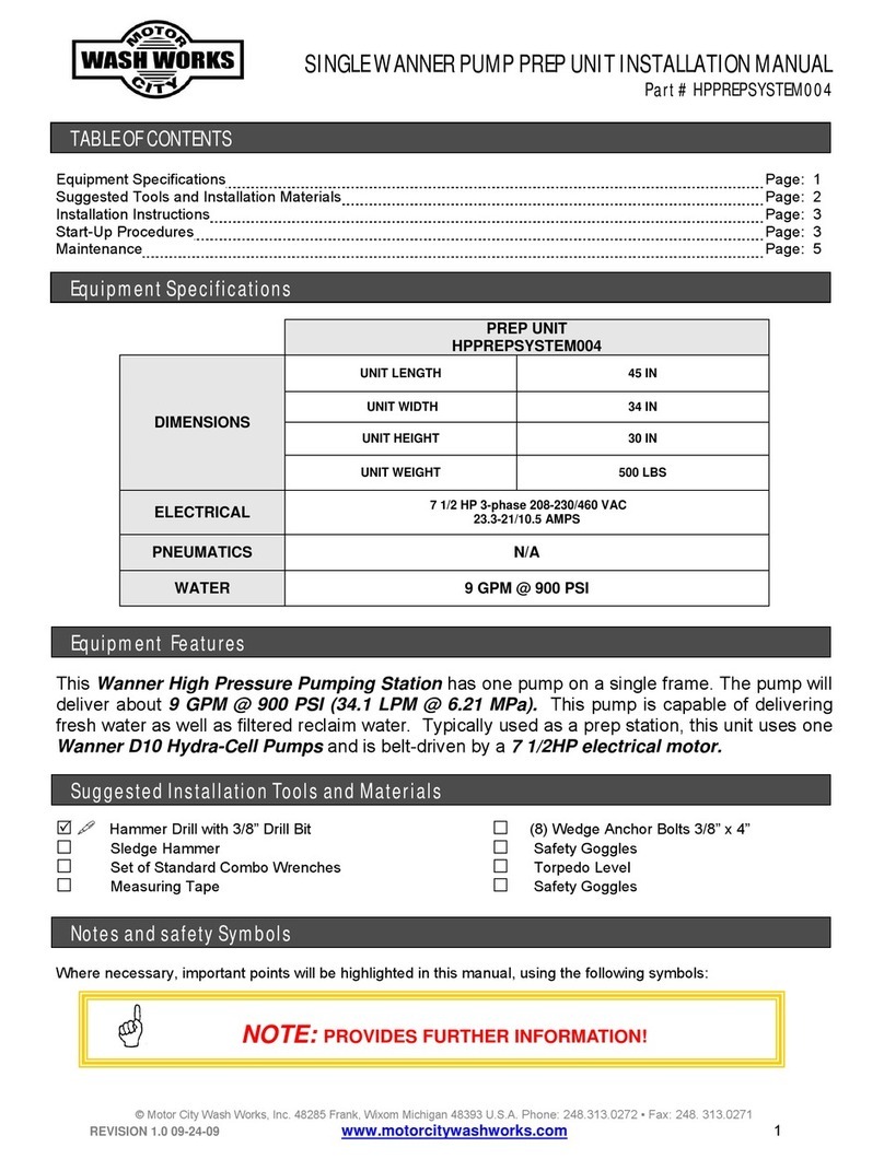
Motor City Wash Works
Motor City Wash Works Wanner HPPREPSYSTEM004 installation manual
Grundfos
Grundfos CR 95 Installation and operating instructions

Axi
Axi FPS Compact Series INSTRUCTION, OPERATING, & MAINTENANCE MANUAL
SAMES KREMLIN
SAMES KREMLIN AIRMIX 15-C50 manual

CAT Pumps
CAT Pumps 781 Service manual
samhydraulik
samhydraulik SH6V 75 Service manual
