MANOSTAT VARISTALTIC KATE 72-620-000 User manual

OPERATING MANUAL
MANOSTAT®VARISTALTIC®
DISPENSERS AND PUMPS
NOTICE D’UTILISATION
DISTRIBUTEURS ET
POMPES MANOSTAT®
VARISTALTIC®
BEDIENUNGSANLEITUNG
MANOSTAT®VARISTALTIC®
DOSIERGERÄTE UND
PUMPEN
MANUAL DE OPERACIÓN
DISTRIBUIDORES Y
BOMBAS MANOSTAT®
VARISTALTIC®
Model Nos. Modèles n° Modellnummern
Números de modelo
KATE 115V 72-620-000
KATE 230V 72-620-230
SPENCER 115V 72-640-000
SPENCER 230V 72-640-230
VARISTALTIC
®
72-640-000 SPENCER
Division of Barnant Company
28W092 Commercial Avenue, Barrington, IL U.S.A. 60010-2392
1-800-637-3739 (U.S. and Canada only) 847-381-7050 (Local) 11-847-381-7050 (outside U.S.)
847-381-7053 (Local Fax) 11-847-381-7053 (Fax outside U.S.)
Edition 10

2
VARISTALTIC
®

3
TABLE OF CONTENTS
Title Page
SAFETY PRECAUTIONS ........................................................................................................................................... 4
Safety ...................................................................................................................................................................... 4
INTRODUCTION AND GENERAL DESCRIPTION .................................................................................................... 5
CONTROLS, INDICATORS AND CONNECTORS ...................................................................................................... 5
KATE Controls......................................................................................................................................................... 5
SPENCER Controls ................................................................................................................................................ 5
SETUP ........................................................................................................................................................................ 6
Tubing Size Selection .............................................................................................................................................. 6
Dispensing Volume Tubing Requirements ............................................................................................................... 7
OPERATION ............................................................................................................................................................... 7
Inserting Tubing ....................................................................................................................................................... 7
For Optimum Tubing Life ......................................................................................................................................... 7
Using the Dispenser Wand or Footswitch................................................................................................................ 8
Priming Tubing and Continuous Pumping Mode ...................................................................................................... 8
Calibration Procedure and Manual Dispensing Operation ....................................................................................... 8
Calibration Check and Timed Dispensing Operation ............................................................................................... 8
Dispensing Cycle—SPENCER OnIy ....................................................................................................................... 9
REMOTE OPERATION ............................................................................................................................................... 9
Description .............................................................................................................................................................. 9
Remote Inputs........................................................................................................................................................10
Run Status Jack ..................................................................................................................................................... 11
MAINTENANCE .........................................................................................................................................................11
Cleaning .................................................................................................................................................................11
Replacement Parts ................................................................................................................................................12
ACCESSORIES .........................................................................................................................................................12
SPECIFICATIONS .....................................................................................................................................................14
WARRANTY ...............................................................................................................................................................15
PRODUCT RETURN ..................................................................................................................................................15
TECHNICAL ASSISTANCE .......................................................................................................................................15
4
NORPRENE, PHARMED, TYGON — Reg TM Norton Co.
Trademarks bearing the ® symbol in this publication are registered in the U.S. and in other countries.
SAFETY PRECAUTIONS
DANGER: Remove power from the pump before any cleaning operation is started.
WARNING: Remove power from the pump before attempting any maintenance.
WARNINGS: Tubing breakage may result in fluid being sprayed from pump. Use appropriate measures to
protect operator and equipment.
Turn pump off before removing or installing tubing. Fingers or loose clothing could be caught in
the pump mechanism.
CAUTIONS: When changing flow direction, allow the pump to come to a complete stop before starting again.
Failure to do so could cause permanent damage to the motor.
Replace the fuse only with one of the same type and rating.The fuse rating and type are stated on
the rear panel.
WARNING: PRODUCT USE LIMITATION
These products are not designed for, nor intended for use in, patient-connected applications, including, but not
limited to, medical and dental use and, accordingly, have not been submitted for FDA approval.
SAFETY
1. Read instructions before operating the unit.
2. Observe safety precautions at all times, especially when pumping dangerous liquids. Always have the clear plastic
cover properly mounted on the pump head and, in general, protect the pump area from accidental spillage of liquid.
3. If the pump runs unusually noisily or if bunching of the tubing in the pump can be observed, make sure the tubing is
clamped down tightly and/or replace it with a new piece of tubing.
4. The MANOSTAT VARISTALTIC dispensers and pumps should be well-grounded at all times.
5. The pump is equipped with a current-limiting circuit that will slow the motor down if any of the following conditions
exist:
a. Tubing that is too hard is loaded in the pump.
b. Incorrect tubing size or wall thickness is loaded in the pump.
c. Tubing is improperly loaded into the pump head.
Note: Use only MANOSTAT tubing.
6. The unit is fused and grounded to protect the operator in the event of short circuits that could be caused by liquid
entering the case.
CAUTION: Replace the fuse only with one of the same type and rating.The fuse rating and type are stated on
the rear panel.
7. Pump should not be used in outdoor or hazardous locations.

5
INTRODUCTION AND GENERAL DESCRIPTION
The MANOSTAT VARISTALTIC dispensers and pumps provide dispensing or continuous pumping of fluids while power
is supplied.
The speed range for the KATE and SPENCER pumps is 24–720 rpm. 115 V pumps are UL and cUL listed. 230 V pumps
are CE certified.
Model No. Description
72-620-000 KATE, Analog Dispenser, 115 V
72-620-230 KATE, Analog Dispenser, 230 V
72-640-000 SPENCER, Analog Dispenser, 115 V
72-640-230 SPENCER, Analog Dispenser, 230 V
CONTROLS, INDICATORS AND CONNECTORS
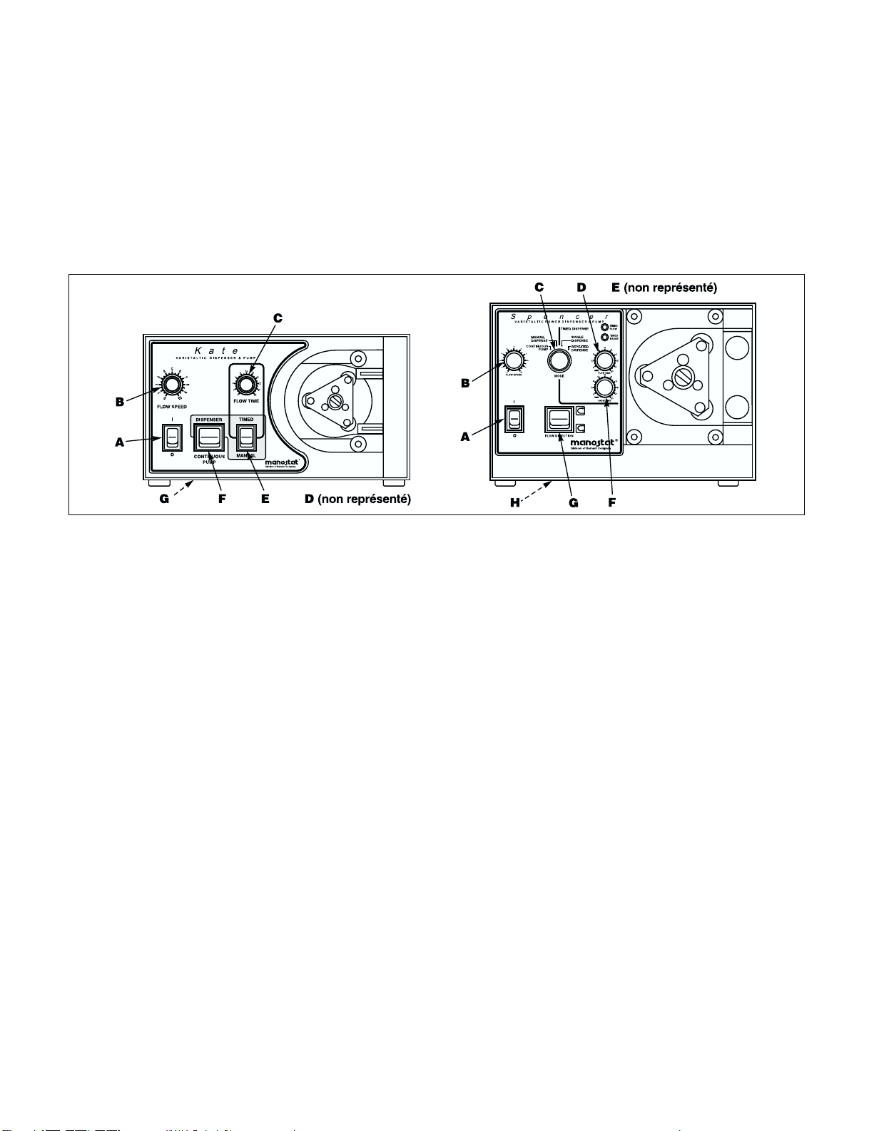
Figure 1.
KATE CONTROLS
A. POWER (ON/OFF) SWITCH: Turns the unit ON or OFF. Glows green when power is ON.
B. FLOW SPEED CONTROL KNOB: Sets the speed of the pump. The higher the number on the dial, the faster the
speed of the pump.
C. FLOW TIME CONTROL KNOB: Sets the time needed to dispense aliquot from 2 to 20 seconds.
D. FRONT PANEL/REMOTE SWITCH: Sets operation from either the front panel controls or remote operation.
E. MANUAL/TIMED DISPENSE SWITCH: Sets the dispensing mode when Footswitch (part no. 73-750-000) or
Dispenser Wand (part no. 73-055-590) is depressed.
F. MODE SWITCH: DISPENSER/CONTINUOUS PUMP: Sets the unit for Dispensing or Pumping.
G. RUN STATUS JACK: Located on the rear panel of the units. The jack contacts are rated for 24 V at 1 A. These
contacts can operate remote relays to start or stop other equipment being utilized in conjunction with the dispens-
ers. Pump contacts are normally open when the pump is not running and closed when the pump is running. A
3.5 mm stereo plug (part no. B-3968, not included with the pump) can be ordered for easy access to the pump
status jack contacts.
SPENCER CONTROLS
A. POWER (ON/OFF) SWITCH: Turns the unit ON or OFF. Glows green when power is ON.
B. FLOW SPEED CONTROL KNOB: Sets the speed of the pump. The higher the number on the dial, the faster the
speed of the pump.
C. MODE SET KNOB: Sets one of four modes of operation: Continuous Pump, Manual Dispense, Timed Single
Dispense and Timed Repeated Dispense.
D. FLOW TIME CONTROL KNOB: Sets the time needed to dispense aliquot from 2 to 20 seconds.
E. FRONT PANEL/REMOTE SWITCH: Sets operation from either the front panel controls or remote operation.

6
F. PAUSE TIME KNOB: Sets the delay interval from 1 to 10 seconds between dispensing cycles.
G. FLOW DIRECTION SWITCH: Sets the direction of the rotation of the pump Clockwise/Counterclockwise.
H. RUN STATUS JACK: Located on the rear panel of the units. The jack contacts are rated for 24 volts at 1 amp. These
contacts can operate remote relays to start or stop other equipment being utilized in conjunction with the dispensers.
Pump contacts are normally open when the pump is not running and closed when the pump is running.A 3.5 mm stereo
plug (part no. B-3968, not included with the pump) can be ordered for easy access to the pump status jack contacts.
NOTE: The signal common for the speed control voltage and current inputs is referenced to earth ground.
SETUP
Unpack the pump and retain all packing material until proper product operation has been verified. Select the tubing
according to the flow desired, while considering chemical compatibility and tubing life. Refer to the enclosed Chemical
Resistance Chart (part no. A-1299-5030) to select appropriate type of tubing for the liquid in use.
TUBING SIZE SELECTION
Flow rate and dispensing volumes are determined by the size of the tubing in the pump head. When tubing links are
used, best performance will be achieved when input and output tubing connected to the link are the same ID as the link.
All tubing inside the pump head must be surface-printed MANOSTAT tubing.
KATE and SPENCER pumps accept tubing ID sizes of 1/32 in. to 5/16 in. For best results, select a tubing size with a
mid-range at the desired flow rate to be pumped. The table below gives an average of flow rates measured with water
at standard pressure and temperature. No lift or discharge pressure is represented.
TUBING SELECTION CHART
*Requires tubing links.
KATE Pumps
(mL/min) SPENCER Pumps
(mL/min)
Silicone Tubing Size
1–37 1/32 in ID (13)* 2–40
6–170 1/16 in ID (14)* 11–29
25–700 1/8 in ID (16) 44–1200
57–1700 3/16 in ID (25) 93–2490
91–2650 1/4 in ID (17) 170–4200
137–3475 5/16 in ID (18) 246–4950
NORPRENE®and PHARMED®Tubing Size
1–40 1/32 in ID (13)* 2–77
8–210 1/16 in ID (14)* 13–350
28–780 1/8 in ID (16) 46–1250
60–1740 3/16 in ID (25) 103–2800
96–2600 1/4 in ID (17) 168–4200
121–3400 5/16 in ID (18) 245–5500
TYGON®Tubing Size
1–25 1/32 in ID (13)* 2–55
6–185 1/16 in ID (14)* 9–320
25–770 1/8 in ID (16) 45–1250
60–1720 3/16 in ID (25) 105–2850
96–2800 1/4 in ID (17) 174–4800
120–3500 5/16 in ID (18) 236–5400

7
DISPENSING VOLUME TUBING REQUIREMENTS
The table below gives an average range of volumes dispensed, measured with water at standard pressure and temperature
using silicone tubing.
*Requires tubing links.
OPERATION
Use only MANOSTAT precision tubing with MANOSTAT pumps to ensure optimum performance. Use of other
tubing may void applicable warranties.
INSERTING TUBING
WARNINGS: Tubing breakage may result in fluid being sprayed from pump. Use appropriate measures to
protect operator and equipment.
Turn pump off before removing or installing tubing. Fingers or loose clothing could be caught in
the pump mechanism.
1. Make sure that the power switch is turned OFF.
2. Remove the two thumb nuts, and then remove the clear plastic cover from the pump head.
3. For Tubing Links: Attach input and output ends of the transfer tubing to the connectors of the tubing link. Insert the
tubing link so that the tie wraps or the flanges of the link are as close as possible to the outside of the pump head.
Manually rotate the roller assembly and guide the tubing between the rollers and the pump head wall.
For Tubing: Insert tubing between the rollers and the pump head housing in the center of the channel (i.e., midway
between the clear plastic pump head cover and the pump head housing bottom). This ensures that the rollers
depress the entire width of the tubing as they turn. Manually rotate the roller assembly and guide the tubing between
the rollers and the pump head wall. When using tubing (not links), there should be a small but visible gap between
the tubing and the pump head housing for about 1/3 to 1/2 of the contact surface at any time. Pull gently on the input
and output sides of the tubing to create a gap between the tubing and the curved pump head housing wall.
4. Replace the clear plastic cover over the pump head, being sure to tighten down the thumb nuts to prevent the tubing
from moving during operation.
KATE: The pump head cover is reversible with different size tubing retainers on each face. If the tubing is smaller
than 3/16 in. ID, place the cover so that the larger tubing retainers hold the tubing. If the tubing is 3/16 in. (Size 25)
or larger, reverse the cover.
SPENCER: Adjust the two screws on the retainer clamp to hold the tubing in place after attaching the clear plastic
cover to the pump head. If the tubing is smaller than 3/16 in. ID (Size 25) and a tubing link is not used, do one of the
following to prevent the tubing from creeping in the pump head:
•Cover the tubing at the clamping points with a small section of a larger tubing to increase the grip.
•Use a tubing connector on the input of the pump head.
FOR OPTIMUM TUBING LIFE
Periodically move the tubing so that a different segment is in the pump head, or change the tubing link. This will avoid
excessive tubing wear at any specific point. Always move the worn tubing to the suction side of the pump.
Silicone
Tubing Size
Volume Dispensed
KATE SPENCER
1/32 in ID Tubing* 0.5–12 mL/cycle 0.5–25 mL/cycle
1/16 in ID Tubing* 1.0–35 mL/cycle 1.0–95 mL/cycle
1/8 in ID Tubing 3.5–190 mL/cycle 2.5–320 mL/cycle
3/16 in ID Tubing 14–420 mL/cycle 9–800 mL/cycle
1/4 in ID Tubing 18–710 mL/cycle 13–1250 mL/cycle
5/16 in ID Tubing 35–1070 mL/cycle 20–1700 mL/cycle

8
USING THE DISPENSER WAND OR FOOTSWITCH
1. Insert the output end of the tubing coming from the pump head through the glass holder of the dispenser wand.
Wetting the tip of the tubing will facilitate insertion.
2. Insert a dispensing tip into the end of the tubing. This step will improve accuracy by reducing dripping (See
ACCESSORIES).
3. Plug the dispenser wand electrical cord into the socket (DB9) on the rear of the unit. (If a footswitch is being used
instead of the dispenser wand, plug the footswitch cord into the same socket.)
4. Check the rear panel label for proper position of the “FRONT PANEL/REMOTE”switch.
PRIMING TUBING AND CONTINUOUS PUMPING MODE
1. Insert appropriate size tubing into pump head and set up with dispenser wand or footswitch. (To select tubing size,
see TUBING SIZE SELECTION.)
2. Insert both intake and output ends of tubing in reservoir to prime.
3. Adjust Flow Speed Control Knob to a setting of ‘1’.
4. Set Mode Switch or Knob to “CONTINUOUS PUMP”.
5. Turn Power Switch to ON.
CAUTION: When changing flow direction, allow the pump to come to a complete stop before starting again.
Failure to do so could cause permanent damage to the motor.
6. Turn Flow Speed Control Knob clockwise to start the pumping action. The higher the number selected, the faster the
speed of the pump. Prime new tubing for at least 5 minutes to achieve a stable flow condition.
CALIBRATION PROCEDURE AND MANUAL DISPENSING OPERATION
Refer to DISPENSING VOLUME TUBING REQUIREMENTS to select appropriate size tubing. Insert tubing into the
pump head. Prime tubing with liquid (See PRIMING TUBING AND CONTINUOUS PUMPING MODE section above).
Materials needed: Graduated cylinder (or other measuring device), timing device or watch with second hand.
1. For KATE: Set the Mode Switch to “DISPENSER”and the Manual/Timed Dispense Switch to “MANUAL”.
For SPENCER: Set the Mode Set Knob to “MANUAL DISPENSE”.
2. Set Flow Speed Control Knob to ‘1’.
3. Set Power Switch to ON.
CAUTION: When changing flow direction, allow the pump to come to a complete stop before starting again.
Failure to do so could cause permanent damage to the motor.
4. To begin pumping action, depress the button on the dispenser wand (or footswitch) and hold. Increase flow speed
knob (clockwise) to adjust to a desired flow. When desired flow is achieved or desired volume is reached, release the
button or footswitch to stop pumping action.
5. For Calibrating: Place the outlet tubing into the graduated cylinder. Depress the button on the dispenser wand (or
footswitch) and time how long it takes to reach the desired volume. As soon as the volume is reached, release the
button and note the time it took to dispense in seconds.
CALIBRATION CHECK AND TIMED DISPENSING OPERATION
Refer to DISPENSING VOLUME TUBING REQUIREMENTS to select the appropriate size tubing and insert into pump
head. Prime tubing with liquid (See PRIMING TUBING AND CONTINUOUS PUMPING MODE).
Material needed: Graduated cylinder (or other measuring device).
1. Set Flow Speed Control Knob to ‘1’.
2. Set Power Switch to ON.
CAUTION: When changing flow direction, allow the pump to come to a complete stop before starting again.
Failure to do so could cause permanent damage to the motor.
3. Set Mode Switch to “CONTINUOUS PUMP”.
4. Increase Flow Speed Control Knob (clockwise) to begin pumping action. Adjust to desired flow or set to the flow that
was used in the CALIBRATION PROCEDURE AND MANUAL DISPENSING OPERATION.

9
5. For KATE: Set the Dispenser/Continuous Pump switch to “DISPENSER”and the Manual/Timed Switch to “TIMED”.
For SPENCER: Set the Mode Set Knob to “SINGLE DISPENSE”.
6. Set the Flow Time Control Knob to desired time or to the time that it took to dispense in CALIBRATION PROCE-
DURE AND MANUAL DISPENSING OPERATION. At 100% maximum setting, approximately 20 seconds of pump
time will result.
7. Place inlet tubing into liquid source and place output end of tubing in graduated volumetric vessel. You will be
dispensing into the graduated cylinder to measure fluid output.
8. Press and release the button on the dispenser wand (or footswitch) to activate dispensing cycle (See USING THE
DISPENSER WAND OR FOOTSWITCH). The unit will dispense for the set time and stop.
9. If the volume delivered is less than the desired volume, increase the Flow Time Control Knob or the Flow Speed
Control Knob setting. If the volume delivered is more than the desired volume, decrease the Flow Time Control Knob
setting or the Flow Speed Control Knob setting. Repeat steps 8 and 9 until desired volume is reached.
NOTE: If the unit does not dispense the desired volume within the desired time setting, check DISPENSING VOLUME
TUBING REQUIREMENTS to choose a larger size tubing.
DISPENSING CYCLE—SPENCER ONLY
Unit dispenses doses on an automatic continuous cycle.
1. Follow procedure for TIMED DISPENSING OPERATION to set volume to be dispensed.
CAUTION: When changing flow direction, allow the pump to come to a complete stop before starting again.
Failure to do so could cause permanent damage to the motor.
2. Set the Mode Set Knob to “DISPENSE CYCLE”.
3. Adjust Pause Time Knob to set the delay time between dispense cycles from 1 to 10 seconds.
4. Press the button on the dispenser wand (or depress footswitch) to initiate the dispensing cycles. The unit will dis-
pense for the set time, pause for the preset delay time, then continue to cycle.
5. To stop the cycle, switch the Mode Set Knob to “TIMED DISPENSE”and the unit will cycle one more time, then stop.
To stop the cycle immediately, switch power to OFF.
REMOTE OPERATION
DESCRIPTION
The pumps can be controlled by external signals connected at the rear panel 9-pin “D”shell connector. The Remote
inputs permit control of the pump by remote equipment or accessories. Figure 2 shows the signal locations of the
connector.
Figure 2. DB9 Pin Configuration
with Wiring Scheme
Pin
No. Description
1 Speed Control Voltage Input (2–10V) (+) input
2 Speed Control Current Input (4–20 mA) (+) input
3 Speed Control Input Reference Common
4 Remote/Local Speed (+) Control
5 Remote/Local Reference Speed (–) Return
6 Start/Stop Reference (–) Return
7 Start/Stop (+) Control
8 Chassis (Earth) Ground
9 Chassis (Earth) Ground
10
REMOTE INPUTS
The FRONT PANEL/REMOTE switch enables remote functions. Switching to FRONT PANEL disables the remote
functions, allowing the front panel controls to operate the pump.
When the FRONT PANEL/REMOTE switch is in the REMOTE position, starting and stopping the pump is controlled by
an external contact closure between pins 6 and 7 (Jumper B), and the pump speed is determined by an externally
supplied 2–10 V or 4–20 mA source. Connection must be made between pins 6 and 7 and a control voltage greater than
2 V or a control current greater than 4 mA must be applied for the pump to run.
If setting the speed from the front panel is desired with remote Start/Stop contact operation, the FRONT PANEL/
REMOTE must again be in the REMOTE position. In addition, Jumper A should be in place. Jumper A connects pin 5
of the “D”shell connector (REMOTE/LOCAL SPEED) to pin 6 (RETURN). Start/Stop will then be controlled from the
rear panel (Jumper B), and the pump speed will be controlled from the front panel. The accessory Footswitch (part no.
73-750-000) and Dispenser Wand (part no. 73-055-590) are connected internally in this way.
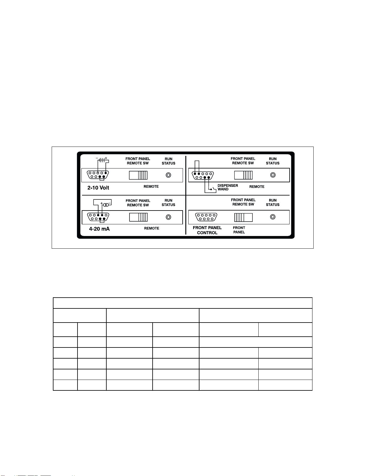
Figure 3 shows four typical wiring configurations: 2–10 V follower, 4–20 mA follower, accessory dispenser wand (or
footswitch), and full front panel control.
NOTE: The signal common for the speed control voltage and current inputs is referenced to earth ground.
The table Operation Summary for the Feature Inputs summarizes the remote input operation.
Operation Summary for the Feature Inputs
Rear Panel Mode
Select Switch
Shorting Jumper
or Contact Closure Functions Activated
Front
Panel Remote Jumper “A”
(Pins 4 to 5)
Jumper “B”
(Pins 6 to 7) Speed Start/Stop
On Off X X Front Panel Control Only
Off On In In Front Panel Remote Start
Off On In Out Front Panel Remote Stop
Off On Out In Remote Remote Start
Off On Out Out Remote Remote Stop
Figure 3. Back Panel Connectors
KEY: X = N/A
Off = Not selected
On = Selected

11
The START/STOP (pin 7) input and REMOTE/LOCAL SPEED (pin 4) input are digital inputs. They are internally pulled
up to +15 V with respect to logic common (RETURNS). They can alternately be driven with open collector logic. For
increased noise immunity, use of contact closures is recommended.
RUN STATUS JACK
The RUN STATUS jack is located on the back panel next to the FRONT PANEL/REMOTE switch. The jack provides a
normally open relay contact rated for 24 V at 1 A that closes whenever the pump is running. The contacts are made
between the tip and first barrel of the jack. The outermost contact of the jack is grounded. A mating 3.5 mm stereo plug
(part no. B-3968, not included with the pump) can be ordered for access to the RUN STATUS contacts.
MAINTENANCE
WARNING: Remove power from the pump before attempting any maintenance.
The speed control circuit has solid-state components that do not require service. An excessive load on the system may,
however, cause the fuse to blow. An indication of an excesive load is a switch that does not light with power applied to
the pump and when the ON-OFF switch is in the ON position. If this condition occurs, remove power from the unit and
remove the fuse from the fuse holder located on the rear of the pump. Replace the fuse with a fuse of the same type and
rating. This information is printed on the rear of the unit.
CAUTION: Replace the fuse only with one of the same type and rating.The fuse rating and type are stated on
the rear panel.
Motor brush life depends on duty cycle and operating speed. Brushes should be inspected every six months or 2000
hours, whichever occurs first, or if erratic operation occurs. Replace when less than 7.6 mm (0.300 in) long.
These models are equipped with a toothed-belt that should be inspected for belt wear at the same interval as the
brushes.The presence of some belt dust at or inside the pump is normal and has no effect on the operation of the pump.
If the belt is slipping, adjust the tension by loosening the motor nuts that secure it to the motor bracket and swing the
motor away from the PC board. Once adjusted, tighten the nut. Do not over-tighten the belt, as this will cause excessive
drive belt wear, bearing wear and noise. Replace the belt if frayed or torn. (See REPLACEMENT PARTS.)
CLEANING
DANGER: Remove power from the pump before any cleaning operation is started.
Keep the pump enclosure clean by using a mild detergent solution. Never immerse nor use excessive fluid when
cleaning the pump.

12
REPLACEMENT PARTS
Description Part Number Qty.
Motor brushes (2) A-4343-CR 2
Brush Cap (1) A-3190-CR 1
Motor 90 V Assembly D-3080-0001 1
Motor 180 V Assembly D-3080-0002 1
Pump Pulley B-3901 1
Motor Pulley A-3166 1
Drive Belt for KATE A-1341-0005 1
Drive Belt for SPENCER A-1341-0006 1
Rubber Foot A-1390-0004 1
Knob (for speed, flow and pause time) 91-126-030 1
Fan (plastic) B-1247-0027 1
Fan (metal) B-1247-0032 1
Fuse (115 V) (T3.15A, 250V, 5 ⫻20 mm) B-1115-0057 1
Fuse (230 V) (T1.6A, 250V, 5 ⫻20 mm) B-1115-0042 1
Pump Head Cover (KATE) 91-055-075 1
Pump Head Cover (SPENCER) 91-065-110 1
Knob (pump cover) B-1083-0063 1
Tubing Clamp (SPENCER) 91-065-130 1
Line Cord 115 V B-3115 1
Line Cord 230 V (Euro) B-2938 1
ACCESSORIES
Tubing Links KATE SPENCER
1/32 in. Tubing Link—NORPRENE, pk of 5 72-305-135 75-305-135
1/16 in. Tubing Link—NORPRENE, pk of 5 72-305-145 75-305-145
1/8 in. Tubing Link—NORPRENE, pk of 5 72-305-165 75-305-165
3/16 in. Tubing Link—NORPRENE, pk of 5 72-305-255 75-305-255
1/4 in. Tubing Link—NORPRENE, pk of 5 72-305-175 75-305-175
1/32 in. Tubing Link—PHARMED, pk of 5 72-301-135 75-301-135
1/16 in. Tubing Link—PHARMED, pk of 5 72-301-145 75-301-145
1/8 in. Tubing Link—PHARMED, pk of 5 72-301-165 75-301-165
3/16 in. Tubing Link—PHARMED, pk of 5 72-301-255 75-301-255
1/4 in. Tubing Link—PHARMED, pk of 5 72-301-175 75-301-175
1/32 in. Tubing Link—Silicone, pk of 5 72-300-135 75-300-135
1/16 in. Tubing Link—Silicone, pk of 5 72-300-145 75-300-145
1/8 in. Tubing Link—Silicone, pk of 5 72-300-165 75-300-165
3/16 in. Tubing Link—Silicone, pk of 5 72-300-255 75-300-255
1/4 in. Tubing Link—Silicone, pk of 5 72-300-175 75-300-175

13
ACCESSORIES (Continued)
Tubing Links KATE SPENCER
1/32 in. Tubing Link—TYGON, pk of 5 72-310-135 75-310-135
1/16 in. Tubing Link—TYGON, pk of 5 72-310-145 75-310-145
1/8 in. Tubing Link—TYGON, pk of 5 72-310-165 75-310-165
3/16 in. Tubing Link—TYGON, pk of 5 72-310-255 75-310-255
1/4 in. Tubing Link—TYGON, pk of 5 72-310-175 75-310-175
PTFE Sinkers —keep intake tube at bottom of reservoir:
Small (1/16 in. to 1/8 in. ID tubing); Large (3/16 in. to 5/16 in.)
Sinkers, set of 2 (one each size) 75-250-100
Sinkers 1/16 in.–1/8 in. ea. 75-250-102
Sinkers 3/16 in.–1/4 in. ea. 75-250-104
Footswitch (115 V or 230 V) 73-750-000
Dispenser Wand (115 V or 230 V) 73-055-590
Autoclavable Dispensing Tips—Glass tip with Luer Lock
for 3/16 in. and 1/4 in. ID tubing 72-648-000
Polypropylene tip w/Luer Lock for 1/16 in. and 1/8 in. ID tubing 72-648-020
Autoclavable Stainless Steel Cannulae
for use with Luer Lock Dispensing tip:
Cannula 16 Gauge 91-015-210
Cannula 13 Gauge 91-015-220
Stereo Plug (3.5 mm) B-3968

14
SPECIFICATIONS
Output:
Speed 24–720 rpm
Torque 120 in-oz (8,6 kg•cm)
Input:
Operating Voltage/Frequency:
Models 72-620-000, 72-640-000 100–130 VAC, 60 Hz, 2.1 A
Models 72-620-230, 72-640-230 190–250 VAC, 50 Hz, 1.3 A
Start/Stop—Local Control:
Input Voltage:
Function Disable 15 VDC Typ.
Function Enable: 0.8 VDC Max.
Input Current:
Function Disable: 100 µA Max. leakage
Function Enable: 1.5mA Max.
Environment:
Operating Temperature: 32 to 104°F (0 to 40°C)
Storage Temperature: –49 to 149°F (–45 to 65°C)
Humidity: 10% to 90% non-condensing
Altitude: Less than 6562 ft (2000 m)
Pollution Degree: Pollution degree 2 (indoor use —lab, office)
Construction:
Dimensions (L ⫻W ⫻H):
Models 72-620-000, 72-620-230 12 in ⫻9 in ⫻6 in (30.5 cm ⫻22.9 cm ⫻15.2 cm)
Models 72-640-000, 72-640-230 12 in ⫻10 in ⫻7 in (30.5 cm ⫻25.4 cm ⫻17.8 cm)
Weight:
Models 72-620-000, 72-620-230 14.9 lbs (6.8 kg)
Models 72-640-000, 72-640-230 17.4 lbs (7.9 kg)
Color: Black
Material: Painted steel housing
Enclosure Rating: IP22 per IEC 529
Compliance: 115V: UL508C, CSA C22.2, No. 14
230V (For CE Mark):
EN61010-1
(EU Low Voltage Directive) and
EN61326
(EU EMC Directive)

15
Printed in U.S.A.
061100
WARRANTY
Use only MANOSTAT precision tubing with MANOSTAT pumps to ensure optimum performance. Use of other
tubing may void applicable warranties.
The Manufacturer warrants this product to be free from significant deviations from published specifications. If repair or
adjustment is necessary within the warranty period, the problem will be corrected at no charge if it is not due to misuse
or abuse on your part, as determined by the manufacturer. Repair costs outside the warranty period, or those resulting
from product misuse or abuse, may be invoiced to you.
The warranty period for this product is noted on the Warranty Card.
PRODUCT RETURN
To limit charges and delays, contact the seller or Manufacturer for authorization and shipping instructions before return-
ing the product, either within or outside of the warranty period. When returning the product, please state the reason for
the return. For your protection, pack the product carefully and insure it against possible damage or loss. Any damages
resulting from improper packaging are your responsibility.
TECHNICAL ASSISTANCE
If you have any questions about the use of this product, contact the Manufacturer or authorized seller.

16
TABLE DES MATIÈRES
Intitulé Page
MESURES DE SÉCURITÉ ............................................................................................................................................................. 17
Sécurité ...................................................................................................................................................................................... 17
INTRODUCTION ET DESCRIPTION GÉNÉRALE ........................................................................................................................ 18
COMMANDES, TÉMOINS ET CONNECTEURS ........................................................................................................................... 18
Commandes KATE..................................................................................................................................................................... 18
Commandes SPENCER ............................................................................................................................................................ 18
INSTALLATION ............................................................................................................................................................................... 19
Sélection du diamètre de tube ................................................................................................................................................... 19
Spécifications de tubes en fonction du volume à distribuer ...................................................................................................... 20
FONCTIONNEMENT ...................................................................................................................................................................... 20
Raccordement de tube .............................................................................................................................................................. 20
Optimisation la durée de service des tubes .............................................................................................................................. 20
Utilisation du tube distributeur ou de l’interrupteur à pédale ..................................................................................................... 20
Amorçage des tubes et mode de pompage continu ................................................................................................................. 21
Étalonnage et distribution manuelle .......................................................................................................................................... 21
Contrôle d’étalonnage et distribution minutée ........................................................................................................................... 21
Cycle de distribution — SPENCER uniquement ....................................................................................................................... 22
TÉLÉCOMMANDE ......................................................................................................................................................................... 22
Description ................................................................................................................................................................................. 22
Entrées pour télécommande ..................................................................................................................................................... 23
Prise RUN STATUS (état) .......................................................................................................................................................... 24
ENTRETIEN .................................................................................................................................................................................... 24
Nettoyage ................................................................................................................................................................................... 24
Pièces de rechange ................................................................................................................................................................... 25
ACCESSOIRES .............................................................................................................................................................................. 25
CARACTÉRISTIQUES TECHNIQUES ........................................................................................................................................... 27
GARANTIE...................................................................................................................................................................................... 28
RETOUR DE MARCHANDISES ..................................................................................................................................................... 28
ASSISTANCE TECHNIQUE ........................................................................................................................................................... 28
17
NORPRENE, PHARMED,TYGON — Marques déposées de Norton Co.
Les marques accompagnées du symbole ® qui apparaissent dans cette publication sont déposées aux États-Unis et dans d’autres pays.
MESURES DE SÉCURITÉ
FRANÇAIS
DANGER : Mettre la pompe hors tension avant de procéder àtoute opération de nettoyage.
AVERTISSEMENT : Mettre la pompe hors tension avant de procéder àtoute opération d’entretien.
AVERTISSEMENTS : Une rupture de tube risque d’entraîner une pulvérisation de fluide hors de la pompe. Prendre
des mesures appropriées pour protéger l’opérateur et le matériel.
Mettre la pompe hors tension avant de débrancher ou de raccorder un tube. Les doigts ou les
vêtements amples risquent de se prendre dans le mécanisme de pompage.
CONSEILS DE
PRUDENCE : Lors de l’inversion du sens de circulation, laisser la pompe s’arrêter complètement avant de la
remettre en marche. Sinon, le moteur risque d’être endommagédéfinitivement.
Remplacer le fusible par un neuf de mêmes type et intensiténominale uniquement. L’intensité
nominale et le type du fusible sont indiqués sur le panneau arrière.
AVERTISSEMENT : LIMITES D’UTILISATION DU PRODUIT
Ces produits ne sont pas conçus, ni destinés à, être utilisés dans des applications avec patients, y compris, entre autres,
les applications médicales et dentaires et n’ont par conséquent pas été soumis à l’agrément de la FDA.
SÉCURITÉ
1. Lire les instructions avant de se servir de l’appareil.
2. Toujours prendre des mesures de sécurité, en particulier lors du pompage de liquides dangereux.Toujours monter correctement
le couvercle en plastique transparent sur la tête de pompe sur la tête et, de façon générale, protéger la zone dans laquelle
se trouve la pompe contre tout renversement accidentel de liquide.
3. Si la pompe est anormalement bruyante ou si un tassement du tube peut être observé dans celle-ci, s’assurer que le tube
est bien serré et/ou le remplacer par une section de tube neuf.
4. Les distributeurs et les pompes MANOSTAT VARISTALTIC doivent toujours être correctement mises à la terre.
5. La pompe est équipée d’un circuit limiteur de courant qui ralentit le moteur dans l’une quelconque des situations suivantes :
a. Un tube trop dur est raccordé à la pompe.
b. Un tube d’un diamètre ou d’une épaisseur de paroi incorrect est raccordé à la pompe.
c. Le tube n’est pas raccordé correctement à la tête de pompe.
Remarque : N’utiliser que des tubes MANOSTAT.
6. L’appareil est protégé par fusible et mis à la terre pour protéger l’opérateur en cas de court-circuit pouvant être provoqué par
la pénétration de liquide dans le carter.
ATTENTION : Remplacer le fusible par un neuf de mêmes type et intensiténominale uniquement. L’intensité
nominale et le type du fusible sont indiqués sur le panneau arrière.
7. La pompe ne doit pas être utilisée à l’extérieur ni dans des endroits dangereux.
18
INTRODUCTION ET DESCRIPTION GÉNÉRALE
Les distributeurs et les pompes MANOSTAT VARISTALTIC permettent une distribution ou un pompage continu de fluide tant qu’ils
sont sous tension.
La plage de vitesse des pompes KATE et SPENCER va de 24 à 720 tr/mn. Les pompes 115 V ont reçu l’agrément UL et cUL. Les
pompes 230 V sont estampillées CE.
N°de modèle Description
72-620-000 KATE, distributeur analogique, 115 V
72-620-230 KATE, distributeur analogique, 230 V
72-640-000 SPENCER, distributeur analogique, 115 V
72-640-230 SPENCER, distributeur analogique, 230 V
COMMANDES,TÉMOINS ET CONNECTEURS
Figure 1.
COMMANDES KATE
A. COMMUTATEUR DE MARCHE/ARRÊT : Il met l’appareil SOUS et HORS TENSION. Il s’allume en vert quand l’appareil est
SOUS TENSION.
B. BOUTON DE RÉGLAGE DE VITESSE DE CIRCULATION : Il permet de régler la vitesse de la pompe. Plus le chiffre du
cadran est élevé, plus la pompe tourne vite.
C. BOUTON DE RÉGLAGE DU TEMPS DE CIRCULATION : Il permet de sélectionner le temps nécessaire pour distribuer un
échantillon entre 2 et 20 secondes.
D. SÉLECTEUR FRONT PANEL/REMOTE : Il permet de commander le fonctionnement à partir du panneau avant ou à distance.
E. SÉLECTEUR DE DISTRIBUTION MANUELLE/MINUTÉE : Il permet de sélectionner le mode de distribution lorsque l’interrupteur
à pédale (pièce n° 73-750-000) ou du tube distributeur (pièce n° 73-055-590) est actionné.
F. SÉLECTEUR DE MODE : DISTRIBUTION/POMPAGE CONTINU : Il permet de régler l’appareil pour la distribution ou le
pompage.
G. PRISE RUN STATUS : Elle se trouve sur le panneau arrière de l’appareil. Ses contacts ont une tension nominale de 24 volts
à 1 A. Ces contacts peuvent actionner des relais à distance pour mettre en marche ou arrêter d’autres appareils utilisés
conjointement avec les distributeurs. Les contacts de la pompe sont normalement ouverts lorsque la pompe est arrêtée et
fermés lorsqu’elle est en marche. Il est possible de commander une fiche stéréo de raccordement de 3,5 mm (pièce n° B-3968,
non fournie avec la pompe) pour accéder aux contacts de la prise d’état de pompe.
COMMANDES SPENCER
A. COMMUTATEUR DE MARCHE/ARRÊT : Il met l’appareil SOUS et HORS TENSION. Il s’allume en vert quand l’appareil est
SOUS TENSION.
B. BOUTON DE RÉGLAGE DE VITESSE DE CIRCULATION : Il permet de régler la vitesse de la pompe. Plus le chiffre du
cadran est élevé, plus la pompe tourne vite.
C. BOUTON DE SÉLECTION DE MODE : Il permet de sélectionner l’un des quatre modes d’exploitation minutée : pompage
continu, distribution manuelle, distribution simple minutée et distribution à répétition minutée.
D. BOUTON DE RÉGLAGE DU TEMPS DE CIRCULATION : Il permet de sélectionner le temps nécessaire pour distribuer un
échantillon entre 2 et 20 secondes.
E. SÉLECTEUR FRONT PANEL/REMOTE : Il permet de commander le fonctionnement à partir du panneau avant ou à distance.
F. BOUTON DE TEMPS DE PAUSE : Il permet de sélectionner un intervalle de 1 à 10 secondes entre les cycles de distribution.

19
G. SÉLECTEUR DE SENS DE CIRCULATION : Il permet de sélectionner le sens de rotation (horaire/antihoraire) de la
pompe.
H. PRISE RUN STATUS : Elle se trouve sur le panneau arrière de l’appareil. Ses contacts ont une tension nominale de 24 volts
à 1 A. Ces contacts peuvent actionner des relais à distance pour mettre en marche ou arrêter d’autres appareils utilisés
conjointement avec les distributeurs. Les contacts de la pompe sont normalement ouverts lorsque la pompe est arrêtée et
fermés lorsqu’elle est en marche. Il est possible de commander une fiche stéréo de raccordement de 3,5 mm (pièce n° B-3968,
non fournie avec la pompe) pour accéder aux contacts de la prise d’état de pompe.
REMARQUE : le signal du commun pour les entrées de tension et d’intensité de réglage de vitesse est mesuré par rapport à
celui de mise à la terre.
INSTALLATION
Déballer la pompe et conserver le matériau d’emballage jusqu’à ce que le fonctionnement correct du produit ait été vérifié.
Sélectionner les tubes en fonction du débit désiré, en tenant compte également de la compatibilité chimique et de la durée de
service des tubes. Se reporter au tableau de résistance aux attaques chimiques fourni (pièce n° A-1299-5030) pour sélectionner
le type de tube adapté au liquide à pomper.
SÉLECTION DU DIAMÈTRE DE TUBE
Le débit et les volumes distribués sont déterminés par le diamètre du tube raccordé dans la tête de pompe. En cas d’utilisation
d’éléments de liaison de tubes, les meilleures performances sont obtenues lorsque les tubes d’entrée et de sortie raccordés à
l’élément de liaison ont le même diamètre intérieur que ce dernier. Tous les tubes qui se trouvent àl’intérieur de la tête de
pompe doivent être des tubes MANOSTAT àimpression en relief.
Les pompes KATE et SPENCER acceptent des tubes de 1/32 à 5/16 po de diamètre intérieur. Pour obtenir les meilleurs résultats,
sélectionner des tubes d’un diamètre permettant d’obtenir un débit correspondant à la moyenne de la plage de débit à laquelle on
désire pomper. Le tableau ci-dessous donne une moyenne des débits mesurés avec de l’eau à la pression et à la température
standard. Aucune pression d’aspiration ni de refoulement n’est indiquée. Aucune pression d’aspiration ou de refoulement n’est
indiquée.
TABLEAU DE SÉLECTION DE TUBE
*Exige des éléments de liaison de tubes.
Pompes KATE
(ml/mn) Pompes SPENCER
(ml/mn)
Diamètre de tube en silicone
1–37 1/32 po diam. int. (13)* 2–40
6–170 1/16 po diam. int. (14)* 11–29
25–700 1/8 po diam. int. (16) 44–1200
57–1700 3/16 po diam. int. (25) 93–2490
91–2650 1/4 po diam. int. (17) 170–4200
137–3475 5/16 po diam. int. (18) 246–4950
Diamètre de tubes NORPRENE®et PHARMED®
1–40 1/32 po diam. int. (13)* 2–77
8–210 1/16 po diam. int. (14)* 13–350
28–780 1/8 po diam. int. (16) 46–1250
60–1740 3/16 po diam. int. (25) 103–2800
96–2600 1/4 po diam. int. (17) 168–4200
121–3400 5/16 po diam. int. (18) 245–5500
Diamètre de tube TYGON®
1–25 1/32 po diam. int. (13)* 2–55
6–185 1/16 po diam. int. (14)* 9–320
25–770 1/8 po diam. int. (16) 45–1250
60–1720 3/16 po diam. int. (25) 105–2850
96–2800 1/4 po diam. int. (17) 174–4800
120–3500 5/16 po diam. int. (18) 236–5400

20
SPÉCIFICATIONS DE TUBES EN FONCTION DU VOLUME ÀDISTRIBUER
Le tableau ci-dessous indique une plage moyenne des volumes distribués, mesurés avec de l’eau àla pression et àla température
standard dans des tubes en silicone.
*Exige des éléments de liaison de tubes.
FONCTIONNEMENT
Utiliser uniquement des tubes MANOSTAT extrudés avec précision avec les pompes MANOSTAT pour garantir des
performances optimales. L’utilisation d’autres tubes peut annuler les garanties applicables.
RACCORDEMENT DE TUBE
AVERTISSEMENTS : Une rupture de tube risque d’entraîner une pulvérisation de fluide hors de la pompe. Prendre des
mesures appropriées pour protéger l’opérateur et le matériel.
Mettre la pompe hors tension avant de débrancher ou de raccorder un tube. Les doigts ou les
vêtements amples risquent de se prendre dans le mécanisme de pompage.
1. S’assurer que l’appareil est hors tension.
2. Retirer les duex écrous àoreilles, puis enlever le couvercle en plastique transparent de la tête de pompe.
3. Éléments de liaison de tubes : Fixer les côtés arrivée et sortie du tube de transfert aux raccords de l’élément de liaison.
Enfoncer ce dernier de façon àce que ses attaches ou brides soient aussi rapprochées que possible de l’extérieur de la tête
de pompe. Faire tourner l’ensemble de rouleaux àla main et guider du tube entre les rouleaux et la paroi de la tête de pompe.
Tube : Enfoncer du tube entre les rouleaux et le carter de la tête de pompe au milieu de la rainure (c’est-à-dire àmi-distance
entre le couvercle en plastique transparent de la tête de pompe et le bas du carter de la tête). Cela garantit que les rouleaux
appuient sur toute la largeur du tube lorsqu’ils tournent. Faire tourner l’ensemble de rouleaux àla main et guider du tube entre
les rouleaux et la paroi de la tête de pompe. Lorsqu’on utilise des tubes (pas des éléments de liaison), il doit toujours y avoir un
espace réduit mais visible entre du tube et le carter de la tête de pompe sur une distance qui doit être comprise entre le tiers
et la moitiéde la surface de contact.Tirer doucement sur les côtés arrivée et sortie du tube pour créer un espace entre du tube
et la paroi incurvée du carter de tête de pompe.
4. Remettre le couvercle en plastique transparent en place sur la tête de pompe, en veillant àserrer les écrous àoreilles pour
empêcher du tube de bouger en cours de fonctionnement.
KATE : Le couvercle de la tête de pompe est réversible, avec des dispositifs de retenue de tubes de différents diamètres sur
chaque face. Si les tubes sont d’un diamètre intérieur inférieur à3/16 po, placer le couvercle de façon àce que les plus gros
dispositifs de retenue les maintiennent. Si les tubes sont d’un diamètre intérieur d’au moins 3/16 po (calibre 25), retourner le
couvercle.
SPENCER : Régler les deux vis du collier de serrage pour maintenir du tube en place après avoir fixéle couvercle en plastique
transparent àla tête de pompe. Si le diamètre intérieur du tube est inférieur à3/16 po (calibre 25) et qu’un élément de liaison
de tubes n’est pas utilisé, prendre l’une des mesures suivantes pour empêcher du tube de glisser dans la tête de pompe :
•Couvrir du tube aux points de raccordement avec un petit morceau de tube de plus grand diamètre pour améliorer le
serrage.
•Poser un raccord sur l’entrée de la tête de pompe.
OPTIMISATION DE LA DURÉE DE SERVICE DES TUBES
Déplacer régulièrement les tubes de façon àce qu’un segment différent soit dans la pompe ou remplacer l’élément de liaison de
tubes. Cela évite une usure excessive des tubes en n’importe quel point précis. Toujours transférer du tube usédu côtéaspiration
de la pompe.
Diamètre de tube
en silicone
Volume distribué
KATE SPENCER
Tubes 1/32 po diam. int.* 0,5–12 ml/cycle 0,5–25 ml/cycle
Tubes 1/16 po diam. int* 1,0–35 ml/cycle 1,0–95 ml/cycle
Tubes 1/8 po diam. int 3,5–190 ml/cycle 2,5–320 ml/cycle
Tubes 3/16 po diam. int 14–420 ml/cycle 9–800 ml/cycle
Tubes 1/4 po diam. int 18–710 ml/cycle 13–1250 ml/cycle
Tubes 5/16 po diam. int 35–1070 ml/cycle 20–1700 ml/cycle
This manual suits for next models
3
Table of contents
Languages:
Popular Dispenser manuals by other brands


physa
physa FOGGIA WHITE user manual

Multiplex
Multiplex FreshBlender Installation, operation and maintenance manual

Millipore
Millipore EZ-Pak Operation and maintenance instructions

Franke
Franke RODX602 Installation and operating instructions

Franke
Franke RODAN RODX618E Installation and operating instructions

U-Line
U-Line H-2624 instructions


