Toto TES100DA Installation instructions

Warranty Registration and Inquiry
Installation and Owner’s Manual
Manual de Instalación y del Propietario
Manual de Instalação e do Proprietário
Manuel d’Installation et d’Utilisation
Automatic Soap Dispenser
Distributeur de savon automatique
Dispensador automático de jabón
Doseador automático de sabonete
TES100DA
TES100AA
For product warranty registration, TOTO U.S.A. Inc. recommends online warranty registration. Please visit
our web site http://www.totousa.com. If you have questions regarding warranty policy or coverage, please
contact TOTO U.S.A. Inc., Customer Service Department, 1155 Southern Road, Morrow, GA 30260
(888) 295-8134 or (678) 466-1300 when calling from outside of U.S.A.


2
TABLE OF CONTENTS
WARNINGS
THANK YOU FOR CHOOSING TOTO!
BEFORE INSTALLATION
Thank You for Choosing TOTO! ............................................................................ 2
How to Use this Product........................................................................................ 10
Warnings ............................................................................................................... 2
Before Installation.................................................................................................. 2
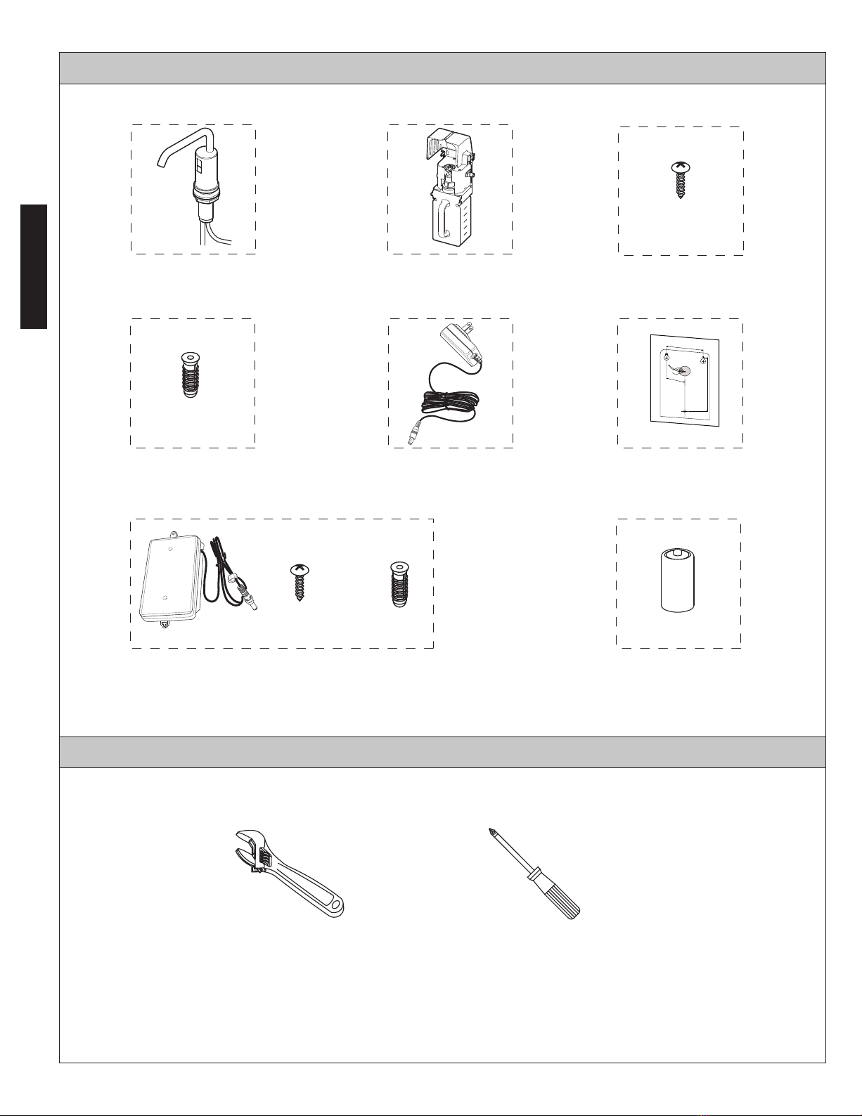
Included Parts ........................................................................................................ 3
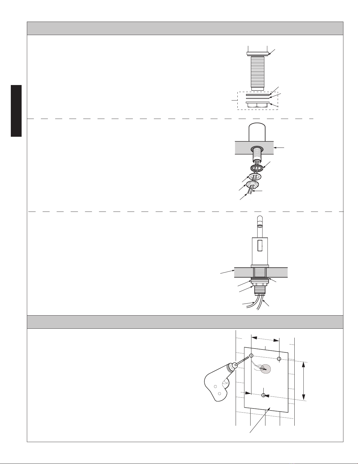
Position of the Dispenser and Tank ..................................................................... 4
Supplement the Soap ........................................................................................... 11
Replacing the Battery [DC Type] .......................................................................... 12
■
■
■
■
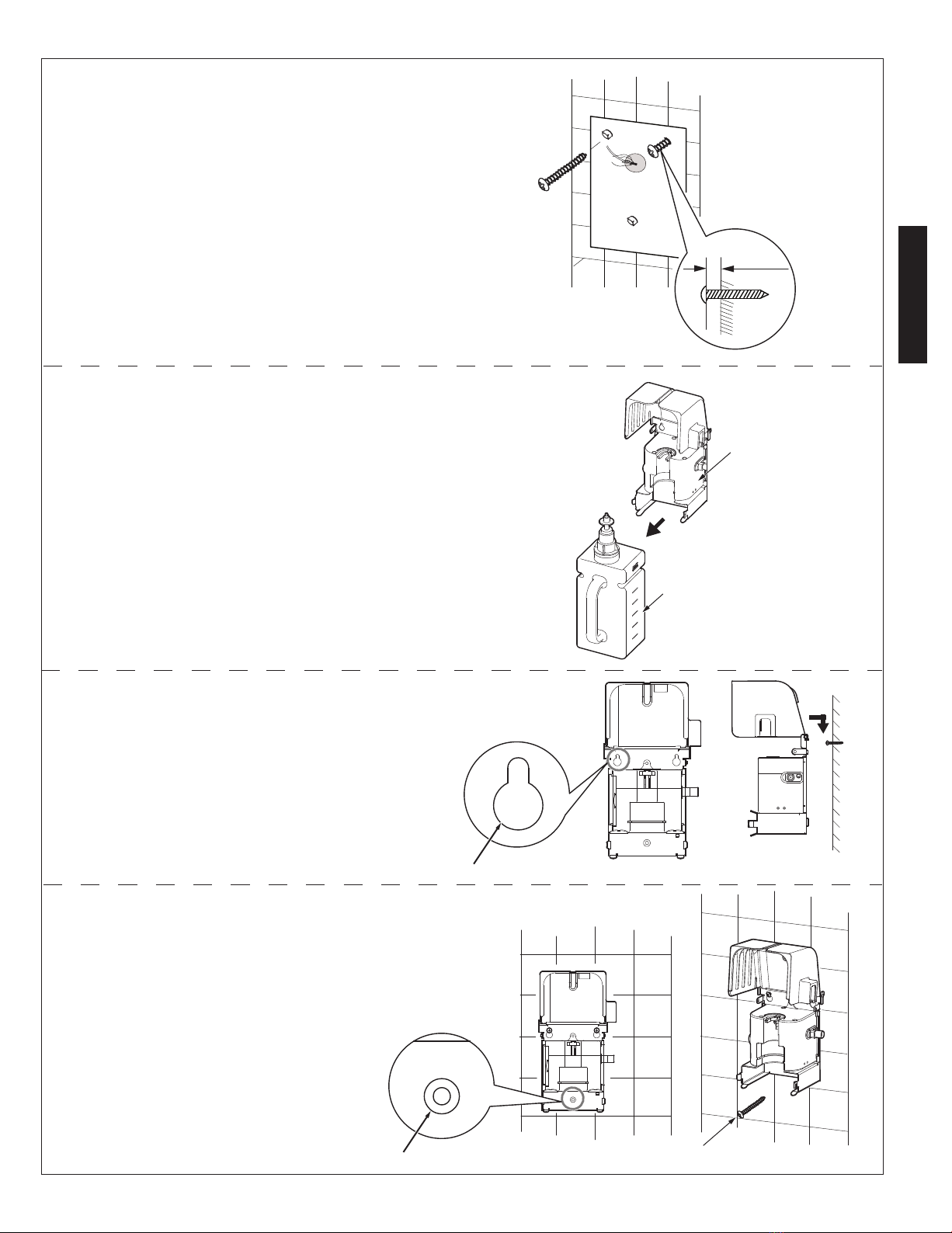
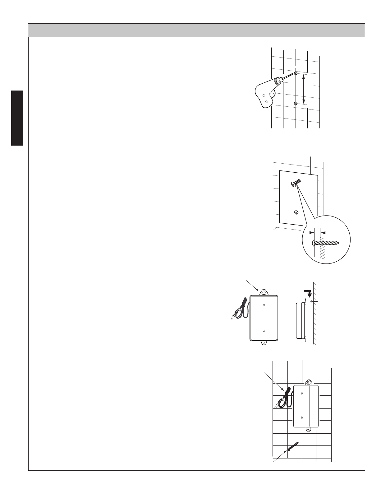
Installation Procedure ......................................................................................... 5-9
Testing .................................................................................................................. 10
■
■
■
■
■
■
Common Tools Needed......................................................................................... 3
Periodic Maintenance ........................................................................................... 13
Warranty................................................................................................................ 15
Troubleshooting .................................................................................................. 14
Care and Cleaning ................................................................................................ 12
Rough-In Dimensions ........................................................................................... 16
The mission of TOTO is to provide the world with healthy, hygienic and more
comfortable lifestyles. We design every product with the balance of form and
function as a guiding principle. Congratulations on your choice.
Please read and adhere to the following notes. Failure to do so could result in
personal injury and/or property damage.
No person other than a service engineer should disassemble, repair or
modify this dispenser, unless it is specifically described in this manual.
Failure to do so may result in electric shock or product malfunction.
Do not use this dispenser in a humid location where condensation may
collect on the surface, especially in a sauna or steam room.
Do not strike or kick the dispenser or controller box, as this may
damage the unit or cause a leak.
Do not use this dispenser if the room temperature drops below freezing.
Make sure the power cord does not come in contact with the hot water
supply line.
Avoid placing any objects within the detection range of the infrared
sensor.
Use only TOTO approved liquid soap.
Read these instructions carefully to ensure proper installation.
TOTO reserves the right to update product design without notice.
Check to make sure you have the parts indicated on the following page.
ENGLISH
■Make sure the electrical outlet is in a position where it will not get wet
during use.
Specifications ...................................................................................................... 14
Long-term suspension of use ............................................................................... 13

3
INCLUDED PARTS
Adjustable Wrench
Spout Assembly Controller
Anchor(3X) AC Adapter(AC Type)
Self-tapping Screw(3X)
COMMON TOOLS NEEDED
Battery Case (DC Type)
Alkaline Battery(D 1.5V)
(4X)(DC Type)
Self-tapping Screw(3X) Anchor(3X)
Screwdriver (Phillips)
Mounting Template
ENGLISH
3-5/32”(80.2mm)
1-37/64”
(40.1mm)
4-41/64”(117.8mm)
Mounting Template
0G398X

4
POSITION OF THE DISPENSER AND TANK
Position of the Dispenser
Hole for installing the dispenser
[1” ~ 1-1/8” (25~28mm) in diameter]
Faucet
Sink
Auto Soap Dispenser
Position of the Tank
Controller
9-1/8”(230mm)
minimum
Tank
Cover
3-1/2"(90mm)
1. Be sure to leave at least 4-3/4"
(120mm) of space between
the soap dispenser and the
faucet to prevent accidental
activation.
1. When installing the
controller, make sure
that the tube and cables
can reach the tank.
2. If the tube is too long,
please cut it to suitable length.
3.Be sure there is adequate space
for refilling/replacing soap tank.
2. Leave 3-1/8"(80mm) of space
maximum from the inside edge
of the sink to the spout installation
hole to ensure that any residual
soap drips from the dispenser
spout into the sink bowl.
(1) Space between the dispenser and
the faucet to be 4-3/4”(120mm) minimum
(2) The distance from the soap
dispenser to the edge of the sink
to be 3-1/8”(80mm) maximum
ENGLISH
Tube length: 17-3/4”(450mm)
Sensor cable length: 19-3/4”(500mm)
Power cord length: 59”(1500mm)
Sensor Cable
Tube
6”~12”(150~300mm)
<4”(100mm) <4”(100mm)
Power cord
Wall Surface
Unit: inches
(mm)
<6”(150mm)

5
ENGLISH
INSTALLATION PROCEDURE - Spout
INSTALLATION PROCEDURE - Controller
Remove Slip washer
Bottom gasket
Nut
Top gasket
Countertop
Countertop
Nut
Sensor cable
Tube
Bottom gasket
Slip washer
Nut
Bottom gasket
Slip washer
Tube
Sensor cable
1.Remove nut, slip washer and bottom gasket.
1.Select the position of the controller
and layout the mounting template.
2.Mark the location of the mounting
holes.
3.Drill 3 holes.
2.Install the spout on the countertop.
3.Install bottom gasket, slip washer
and nut in that order.
4.Confirm the alignment of spout and
tighten nut.
Make sure the sensor cable and soap
tube can reach the mounting template.
Depth : 1”(25mm)
Important: Mounting template to be level.
3-1/8”
(80mm)
4-5/8”
(118mm)
Mounting template
Size: 7/64" (3mm) without anchor
1/4" (7mm) with anchor
1-9/16”
(40mm)

6
ENGLISH
Controller
Tank
Self-tapping screw
4.Insert self-tapping screws into the upper
two holes until there is a 1/4”(6mm) gap
between head of screw and wall.
5.Remove the tank from controller.
6.Hang the controller on the
two screws.
7.Insert a self-tapping screw through
bottom hole of controller and tighten.
Use anchors if necessary.
1/4”
(6mm)

7
ENGLISH
INSTALLATION PROCEDURE - Tank
Liquid soap
MAX fill line
Tank
Pump Unit
Bottom of pump
8.Connect sensor cables.
1.Remove pump unit from the tank.
2.Slowly pour liquid soap into the tank.
3.Replace the pump by pushing it down firmly
over the tank opening until it snaps in place.
NOTE:
NOTE: Fill the tank up to MAX fill line.
NOTE: Use only TOTO approved liquid soap.
Keep pump unit clean while filling
soap, especially keep bottom of
pump off from floor.
Sensor cable
from controller
Sensor cable
from spout
Tube

8
ENGLISH
AC Adapter
[AC Type]
Cover
AC adapter cable
INSTALLATION PROCEDURE - Connection to Power Supply
4.Connect the tube to pump.
(Insert the barb into the tube fully)
5.Mount the tank to the controller.
1.Connect AC adapter cable to controller.
2.Plug the AC adapter into an (appropriate) outlet.
3.Close the cover.
NOTE: Do not plug in the AC adapter
upside down.
Tube
Tube
Tank
Pump
NOTE:Make sure the length of the
tube prevents the bottom of
pump from contacting the
floor when the tank is
removed for refilling.

9
Self-tapping screw
INSTALLATION PROCEDURE - Battery Box
[DC Type]
1.Select position for the battery case.
Make sure the power supply cable is capable
of reaching the controller.
2.Mark the location of the mounting holes.
4.Insert a self-tapping screw into upper hole until
there is a 1/4”(6mm) gap between head of
screw and wall.
Use anchors if necessary.
3.Drill 2 holes. Depth : 1”(25mm)
5.Hang the battery case on the screw.
6.Insert a self-tapping screw through bottom hole
of case and tighten.
7.Connect power cord to controller.
ENGLISH
160mm
1/4”
(6mm)
Size : 7/64" (3mm) without anchor
1/4" (7mm) with anchor
Power cord

10
TESTING
HOW TO USE THIS PRODUCT
Place hands under spout.
150±15mm
5-7/8"±5/8"
After installation is complete, confirm
that the dispenser is working properly
using the following method.
1.Place your hands under the spout
and hold them in place until soap
is discharged.
● Proper amount of soap is dispensed
automatically.
Caution: Please do not put liquid soap
on the spout. If the sensor
gets dirty, it could cause malfunction.
Sensor sensing range is
5-7/8"±5/8"(150mm±15mm).
Caution: Please do not obstruct the
spout opening.
The soap might go flying off
in an unexpected direction.
NOTE: Make sure there is no soap
leaking from the tube and connections.
Sensor
window
ENGLISH

11
ENGLISH
Liquid soap
MAX fill line
Tank
Pump unit
REFILLING THE SOAP
1.Open the cover.
2.Remove the tank from the controller.
3.Remove pump unit from the tank.
4.Slowly pour liquid soap into the tank.
6.Mount the tank to the controller.
7.Close the cover.
5.Replace the pump by pushing it down firmly
over the tank opening until it snaps in place.
NOTE: Fill the tank up to MAX fill line.
NOTE: Use only TOTO approved liquid soap.
Tank
Cover
Controller
Tank
Cover
Pump unit
Bottom of Pump
NOTE: Clean container before refilling.
8.Purge the line by holding hands
under spout until soap is discharged.
Dispenser can be actuated up to
ten times consecutively while
holding hands under the spout
immediately after refilling .
The soap dispenser keeps track of soap usage by counting
soap dispenses.
It displays a flashing green LED indicator light to signal low
soap level.
A power interruption (AC type) or changing batteries (DC type)
disrupts the count and could prevent the indicator light from flashing.
To ensure accuracy, always add soap to the MAX line once
power is restored.

12
REPLACING THE BATTERY [DC Type]
Screws
Batteries
+
-
-
+
CARE AND CLEANING
Sensor window
1.Remove cover of battery case.
2.Install four (4) D size alkaline batteries.
3.Replace battery case cover.
4.Tighten screws.
Battery
case cover
NOTE: Make sure the batteries are
installed in correct orientation
(polarity).
● For Light Cleaning
● When cleaning around the sensor,
please be careful not to scratch
the surface of the sensor window.
Wipe away any debris adhering to the
spout or sensor.
Wipe away debris with a damp cloth
containing a suitable amount of a neutral,
dishwashing detergent.
Then wipe clean with a damp cloth.
● For Heavy-Duty Cleaning
● Do not use detergent that might
hurt the surface of spout.
These include:
● Detergents containing acid, chlorine
bleach or alkali.
● Detergents that are coarse granules in
nature, such as polishing powder.
● Solvents such as paint thinner or benzene.
● Abrasive aids such as nylon scrubbers/brushes,
steel wool, etc.
Battery
case
ENGLISH

13
ENGLISH
Tank
PERIODIC MAINTENANCE
● For Tank Cleaning
● Once a month:
● Twice a year:
Wash tank out with water to keep it clean.
1.Check all tube connections for any signs of leakage.
1.Check all fixed connections and tighten as needed.
2.Wipe away any dust on AC adapter [AC type only].
● For Nozzle Cleaning Nozzle
Brush
Clean the nozzle with a soft brush to
remove any dirt form the screen.
Pump Unit
● For Pump Unit Cleaning
If the pump sticks or backflow occurs,
wash pump unit with water while holding
upside down and manually squeeze pump
several times.
LONG-TERM SUSPENSION OF USE
If there will be long periods of time where the dispenser will not be used,
remove all soap from dispenser using the following method.
1.Remove soap from tank and wash tank out with water.
2.Fill the tank with water and set up the dispenser as usual.
3.Flush the line with water by activating dispenser until no soap comes out from
spout . Refill water if necessary.
4.Discard any water left in tank and allow tank to dry.
5.Place the tank back into the controller.
6.Disconnect the power supply until use resumes.

14
ENGLISH
TROUBLESHOOTING
Problem Operating Solution
No soap comes out
Green LED flashing Fill tank with liquid soap.
Red LED flashing Battery is low Replace batteries.
Green LED solid on
Clean the pump unit.
Soap won’t
stop running
- Sensor window is dirty Clean sensor window.
- There is an obstruction in front of sensor window Remove the obstruction.
Soap comes out
unexpectedlly
Sensor window is dirty Clean sensor window.
Soap will be automatic dispersed after 48 hours of non-usage to
prevent clogging. -
Amount of dispensed
soap is small Pump is not working correctly Clean the pump unit.
SPECIFICATIONS
Power supply
Sensor detection range 5-7/8"±5/8"(150mm±15mm)
Ambient temperature 32~104°F (1~40°C)
Humidity Max. 90% RH
Cause
Soap is low
Pump is sticking
-Clean sensor window.
- Sensor cable is disconnected Connect cable.
-Remove the obstruction.
Sensor window is dirty
There is an obstruction in front of sensor window
- Connect cable.
- Tube is disconnected Connect tube.
-Plug in the AC adapter.
Power supply (AC adapter or battery box) is disconnected
AC adapter is not plugged in
-
-
-
Change to TOTO
approved liquid soap.
Soap viscosity is high
Tank capacity 50 oz (1500ml)
Soap volume 0.03-0.04 oz (0.8-1.2ml)
Type TES100AA TES100DA
AC
DC
AC 100~240V 4×D 1.5V alkaline batteries
For use with Listed Class 2 power
supply or limited power source

15
ENGLISH
WARRANTY
1. TOTO ® warrants its electronic flush valves, faucets and soap dispensers (“Product”) to be free from defects in
materials and workmanship during normal use when properly installed and serviced, for a period of three (3) years
from date of purchase. This limited warranty is extended only to the ORIGINAL PURCHASER of the Product and is
not transferable to any third party, including but not limited to any subsequent purchaser or owner of the Product.
This warranty applies only to TOTO Product purchased and installed in North, Central and South America.
2. TOTO’s obligations under this warranty are limited to repair, replacement or other appropriate adjustment, at
TOTO’s option, of the Product or parts found to be defective in normal use, provided that such Product was properly
installed, used and serviced in accordance with instructions. TOTO reserves the right to make such inspections as
may be necessary in order to determine the cause of the defect. TOTO will not charge for labor or parts in
connection with warranty repairs or replacements. TOTO is not responsible for the cost of removal, return and/or
reinstallation of the Product.
4. In order for this limited warranty to be valid, proof of purchase is required. TOTO encourages warranty registration
upon purchase to create a record of Product ownership at http://www.se is required. TOTO encourages warranty
registration upon and failure to register will not diminish your limited warranty rights.
5. THIS WARRANTY GIVES YOU SPECIFIC LEGAL RIGHTS. YOU MAY HAVE OTHER RIGHTS WHICH VARY
FROM STATE TO STATE, PROVINCE TO PROVINCE OR COUNTRY TO COUNTRY.
6. To obtain warranty repair service under this warranty, you must take the Product or deliver it prepaid to a TOTO
service facility together with proof of purchase (original sales receipt) and a letter stating the problem, or contact
a TOTO distributor or products service contractor, or write directly to TOTO U.S.A., INC., 1155 Southern Road,
Morrow, GA 30260 (888) 295 8134 or (678) 466-1300, if outside the U.S.A. If, because of the size of the Product
or nature of the defect, the Product cannot be returned to TOTO, receipt by TOTO of written notice of the defect
together with proof of purchase (original sales receipt) shall constitute delivery. In such case, TOTO may choose
to repair the Product at the purchaser’s location or pay to transport the Product to a service facility.
THIS WRITTEN WARRANTY IS THE ONLY WARRANTY MADE BY TOTO. REPAIR, REPLACEMENT OR OTHER APPROPRIATE
ADJUSTMENT AS PROVIDED UNDER THIS WARRANTY SHALL BE THE EXCLUSIVE REMEDY AVAILABLE TO THE ORIGINAL
PURCHASER. TOTO SHALL NOT BE RESPONSIBLE FOR LOSS OF THE PRODUCT OR FOR OTHER INCIDENTAL, SPECIAL
OR CONSEQUENTIAL DAMAGES OR EXPENSES INCURRED BY THE ORIGINAL PURCHASER, OR FOR LABOR OR OTHER
COSTS DUE TO INSTALLATION OR REMOVAL, OR COSTS OF REPAIRS BY OTHERS, OR FOR ANY OTHER EXPENSE NOT
SPECIFICALLY STATED ABOVE. IN NO EVENT WILL TOTO’S RESPONSIBILITY EXCEED THE PURCHASE PRICE OF THE
PRODUCT. EXCEPT TO THE EXTENT PROHIBITED BY APPLICABLE LAW, ANY IMPLIED WARRANTIES, INCLUDING THAT
OF MERCHANTABILITY OR FITNESS FOR USE OR FOR A PARTICULAR PURPOSE, ARE EXPRESSLY DISCLAIMED. SOME
STATES DO NOT ALLOW LIMITATIONS ON HOW LONG AN IMPLIED WARRANTY LASTS, OR THE EXCLUSION OR
LIMITATION OF INCIDENTAL OR CONSEQUENTIAL DAMAGES, SO THE ABOVE LIMITATION AND EXCLUSION MAY NOT
APPLY TO YOU.
3. This warranty does not apply to the following items:
a. Damage or loss sustained in a natural calamity such as fire, earthquake, flood, thunder, electrical storm, etc.
b. Damage or loss resulting from any accident, unreasonable use, misuse, abuse, negligence, or improper
care, cleaning, or maintenance of the Product.
c. Damage or loss resulting from sediments or foreign matter contained in a liquid soap system.
d. Damage or loss resulting from improper installation or from installation of the Product in a harsh and/or
hazardous environment, or improper removal, repair or modification of the Product.
e. Damage or loss resulting from electrical surges or lightning strikes or other acts which are not the fault of
TOTO or which the Product is not specified to tolerate.
f. Damage or loss resulting from normal and customary wear and tear, such as gloss reduction, scratching or
fading over time due to use, cleaning practices or water or atmospheric conditions, including but not limited
to, the use of bleach, alkali, acid cleaners, dry (powder) cleaners or any other abrasive cleaners or the use
of metal or nylon scrubbers.

16
ENGLISH
ROUGH - IN / DIMENSIONS
Floor surface
Wall Surface
Unit: inches(mm)
FRONT VIEW
SIDE VIEW
Floor surface
1-7/16”(36mm)
6”~12”(150~300mm)
12-3/16”(310mm)
5-3/16”(131mm)
5-3/16”(131mm)
4-5/16”
(109mm)
5-3/8”(135mm)
Tube lengh:17-3/4”(450mm)
Sensor cable length:19-3/4”(500mm)
1-3/16”(30mm)
max deck thickness
Power cord length: 59”(1500mm)
Min 1"(25mm)
Max 1-1/4"(32mm)

17
FRANÇAIS
TABLE DES MATIÈRES
AVERTISSEMENTS
MERCI D’AVOIR CHOISI TOTO!
AVANT L’INSTALLATION
Merci d’avoir choisi TOTO! ............................................................................................. 17
Comment utiliser ce produit ............................................................................................ 25
Avertissements ............................................................................................................... 17
Avant l’installation ........................................................................................................... 17
Pièces fournies ................................................................................................................ 18
Installation du distributeur et du réservoir ........................................................................ 19
Remplissage de savon .................................................................................................... 26
Remplacement des pile [Type CC] ................................................................................. 26
■
■
■
■
Procédure d’installation .............................................................................................. 20-24
Essai ............................................................................................................................... 25
■
■
■
■
■
■
Outils communs requis ................................................................................................... 18
Entretien périodique ....................................................................................................... 28
Garantie ........................................................................................................................... 30
Dépannage ..................................................................................................................... 29
Soin et nettoyage ............................................................................................................ 27
Dimensions de robinetterie brute .................................................................................... 31
La mission de TOTO est d’offrir au monde entier un style de vie sain, hygiénique et
plus confortable. Comme principe de base, nous concevons chaque produit de manière
à proposer un équilibre entre la forme et la fonction. Félicitations pour votre choix.
Veuillez lire et respecter les remarques suivantes. Le non-respect de cet
avertissement pourrait entraîner des blessures et/ou des dommages.
Personne d’autre qu’un technicien d’entretien ne doit démonter, réparer
ou modifier ce distributeur, à moins que ce ne soit décrit spécialement
dans ce manuel. Le non-respect de cette consigne pourrait entraîner
une décharge électrique ou un problème de fonctionnement du produit.
N’utilisez pas ce distributeur dans des endroits humides où la condensation
pourrait s’accumuler à la surface, notamment dans un sauna ou un
bain à vapeur.
Ne frappez pas et ne donnez pas de coups de pied au distributeur ou au
boîtier du contrôleur, car cela pourrait endommager l’appareil ou provoquer
une fuite.
N’utilisez pas ce distributeur si la température ambiante diminue au
point de congélation.
Assurez-vous que le câble d’alimentation n’entre pas en contact avec la
conduite d’alimentation en eau chaude.
Évitez de placer tout objet dans la zone de détection du capteur infrarouge.
Utilisez uniquement un savon liquide approuvé par TOTO.
Lisez ces instructions attentivement pour assurer une installation adéquate.
TOTO se réserve le droit de modifier la conception du produit sans préavis.
Assurez-vous d’avoir toutes les pièces indiquées à la page suivante.
Spécification .................................................................................................................. 29
■Assurez-vous que la prise électrique est dans une position où il ne sera
pas mouillé pendant l'utilisation.
Suspension à long terme de l'utilisation .......................................................................... 28

18
FRANÇAIS
PIÈCES INCLUSES
Clé ajustable
Assemblage du bec Contrôleur
Ancrage (3X) Adaptateur CA (Type CA)
Vis auto-taraudeuse (x3)
OUTILS COMMUNS REQUIS
Logement des piles (Type CC)
Pile alcaline (1,5 V)
(x4) (Type cc)
Vis auto-taraudeuse (x3) Ancrage (3X)
Tournevis (tête étoilée)
Gabarit de montage
3-5/32”(80.2mm)
1-37/64”
(40.1mm)
4-41/64”(117.8mm)
Mounting Template
0G398X

19
FRANÇAIS
INSTALLATION DU DISTRIBUTEUR ET DU RÉSERVOIR
Trou pour l’installation du distributeur
[1” ~ 1-1/8” (25~28mm) de diamètre]
Robinet
Évier
Position du réservoir
Contrôleur
9-1/8”(230mm)
Minimum
Réservoir
Couvercle
3-1/2"(90mm)
1. Assurez-vous de laisser un
espace d’au moins 4-3/4"(120mm)
entre le distributeur de savon
et le robinet pour éviter une
activation accidentelle.
1. Lors de l’installation du
contrôleur, assurez-vous
que le tuyau et les câbles
puissent atteindre le
réservoir.
2. Si le tuyau est trop long,
veuillez le couper à une
longueur convenable
3. Assurez-vous qu’il y ait un
espace adéquat pour le
remplissage/la réinstallation
du réservoir à savon.
2. Laissez un espace de
3-1/8"(80mm) entre le rebord
interne de l’évier et les trous
d’installation du bec pour vous
assurer que le savon résiduel
du bec de distributeur puisse
s’égoutter dans l’évier.
(1) L’espace minimal entre le distributeur
et le robinet doit être de 4-3/4"(120mm)
(2) La distance maximale entre le
distributeur de savon et le rebord de
l’évier doit être de 3-1/8”(80mm)
Position du distributeur
Distributeur de savon automatique
Longueur du flexible:
17-3/4”(450mm)
Longueur du câble du
capteur : 19-3/4”(500mm)
Longueur du cordon électrique: 59”(1500mm)
Câble du
capteur
Flexible
6”~12”(150~300mm)
<4”(100mm) <4”(100mm)
Power cord
Surface du
mur
Unité : pouces
(mm)
<6”(150mm)
This manual suits for next models
1
Table of contents
Languages:
Other Toto Dispenser manuals

Toto
Toto DSE102E User manual

Toto
Toto TS125R User manual

Toto
Toto TES201A Series Installation instructions

Toto
Toto TLK01101 Series User manual

Toto
Toto DSE101E User manual

Toto
Toto TLK01103 Series User manual

Toto
Toto YH700AD Installation instructions

Toto
Toto TS126AR User manual

Toto
Toto TES100AA Installation instructions

Toto
Toto TLK03001G Installation instructions