Manrose Cucina User manual

Installation Instructions Specifications are subject to change without notice Page 1
Cucina 100mm Kitchen Fan
Thank you for purchasing this quality kitchen fan.
To ensure correct function and safety, please read all instructions before using the product and keep all instructions for future reference.
Mounting Switching Order Code
Wall, Panel or Ceiling Pull Cord FAN7201
When using electrical appliances, basic safety precautions should always
be followed to reduce the risk of fire, electrical shock and personal injury.
ABCDEØF
231 261 137 79 58 98
DIMENSIONS
SPECIFICATIONS
Duct
(mm)
Fan
Speed
Max.
Fan Watts
(W)
Max.
Fan Pressure
(Pa)
Free Air Fan Performance Specific
Fan Power
(W/l/s)
Sound
dB(A)
(l/s) (m3/hr)
100 High
Medium
60
41
236
140
73
39
263
140
0.82
1.05
52
38
TECHNICAL
Supply Max. Operating Temp IP Rating
220-240V AC, 50Hz 40°C IPX4
Compliance: AS/NZS60335-2.80:2016
This powerful centrifugal fan, designed for easy installation and low
running noise, features kitchen and laundry installation boost levels
as well as a low speed option for long term trickle. The fan also
features a washable grease filter.
For best results, Simx recommend this product for either kitchen or
laundry applications.
Following these installation instructions, this product will comply with
the G4 Building Code for kitchens and bathrooms once installed.
The Healthy Homes Standard requirement for bathroom or kitchen
installation in a rental property is also met.
A
B
C D
E
F
Installation Instructions Specifications are subject to change without notice Page 2
Cucina 100mm Kitchen Fan
REGULATIONS AND STANDARDS
Choosing the Right Fan to Comply
Fans cannot be selected on the basis of free-air performance only. Fans must now be selected on the basis of the complete installed system
performance for a designated room as per the table below.
1) Toilets only require ventilation if they have no openable windows
2) Simx recommends 40 l/s for laundries with unvented non-condensing tumble dryers as covered in AS 1668: Part 2 2012
New Zealand Building Code and Healthy Homes
The following two category requirements have been established for mandatory extraction ventilation in New Zealand.
The New Zealand Building Code for New Building Consents
The building regulatory system sets out a framework to promote good quality decisions being made during the Building Consent process. The
legislation and regulations work together, as the building regulatory system. The functional clauses of the NZ Building Code are grouped and
described by a letter and number. Clause G of the NZ Building Code covers services, with G4 setting out the performance requirements for
ventilation. The Building Code is enshrined in law. The New Zealand Building Code, G4, has been changed. This is supported by Acceptable Solution
G4/AS1 Fourth Edition that specifies mechanical ventilation in accommodation units that contain cooktops, showers and baths.
Residential Tenancy Regulations to the Healthy Homes Standards
Residential Tenancy Regulations for rental properties only is changing to the Healthy Homes Standards, sub part 4 - Ventilation Standards.
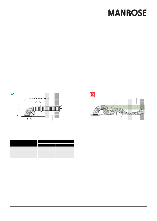
Complying with the Acceptable Solution G4/AS1
To comply, the mandatory mechanical extract system must deliver minimum airflow rates for the complete installed ventilation system. This means
that airflow rates must deliver the airflow after resistance of the ducting, internal and external grilles, as well as all other accessories, such as
backdraught shutters, are included.
Fan selection is important as some types are far better at overcoming ducting system pressure drops.
Additionally, the quality of the ducting system installation can be all important. Rigid duct systems are best as they are the most efficient. Good
installation practice is vital for flexible duct systems.
Room Airflow Rate (min.)
Intermittent Continuous
Toilet1) 25 l/s 10 l/s
Bathroom/shower 25 l/s 10 l/s
Laundry2) 40 l/s -
Kitchen 50 l/s 12 l/s
Duct Supports
Exterior Grille
Airflow
Airflow
Interior Grille
Sealant Cavity
Sleeve
Maximum length of
flexible ducting
Minimum radius =
diameter of ducting
Preferred flexible
ducting route
Peaks and troughs
Restrictions

Installation Instructions Specifications are subject to change without notice Page 3
Cucina 100mm Kitchen Fan
KITCHEN FAN INSTALLATION AND ELECTRICAL CONNECTION MUST
BE CARRIED OUT BY A REGISTERED ELECTRICIAN
BEFORE INSTALLING THE KITCHEN FAN, MAKE SURE YOU HAVE TURNED OFF THE MAIN ELECTRICITY
SUPPLY. DO NOT TURN IT BACK ON UNTIL THE KITCHEN FAN IS FULLY
INSTALLED AND READY TO USE.
ALL ELECTRICAL WORK MUST BE CARRIED OUT BY A REGISTERED ELECTRICIAN IN ACCORDANCE
WITH THE LATEST WIRING RULES AS/NZS3000.
CAUTION
• Before use, please check that the supply voltage and that of the appliance are the same (see product rating label).
• All wiring and wiring connections must comply with all current national wiring rules and regulations including AS/NZS3000:2018, or latest
edition thereof.
• Any changes or modifications made or attempted to this product, without the prior written approval of the manufacturer, will void any and all
stated warranties.
• This fan is not intended for use by persons (including children) with reduced physical, sensory or mental capabilities, or lack of experience and
knowledge, unless they are capable of, and have been given supervision or instruction concerning use of the appliance by a person responsible
for their safety.
• Precautions must be taken to avoid the back-flow of gases into the room from the open flue of gas or other fuel-burning appliances.
WARNING
• Do not insert or allow foreign objects to enter any ventilation openings, as this may cause an electric shock, fire or damage to the fan.
• Do not put fingers or foreign objects into the grille while in operation.
• To prevent overheating of this fan, keep the air inlets and outlets clean and free of anything that may cause blockage. Check all inlets and
outlets from time to time to ensure it is clear of any dirt or dust accumulation. DO NOT COVER.
• Do not use it in areas where gasoline, paint, or flammable liquids are used or stored.
• This product contains recyclable materials. Do not dispose of this product as unsorted council waste. Please contact your local council for the
nearest collection point.
KITCHEN FAN AND ANCILLARY CONTROL EQUIPMENT MUST BE ISOLATED
FROM THE POWER SUPPLY DURING INSTALLATION OR MAINTENANCE
IMPORTANT
• The fan should only be used in conjuction with fixed wiring.
• The cross-sectional area of supply cord used should be ranged from 1 -1.5mm2with the appropriate sized protection device.
• Cable entry can only be made from the rear of the fan.
• The fan is suitable for connection to 220-240V AC 50Hz supply.
• The fan is a Class ll double insulated product and MUST NOT be earthed.
• Check all connections have been made correctly and securely fastened.
• Ensure the impeller rotates and is free of any obstructions.

Installation Instructions Specifications are subject to change without notice Page 4
Cucina 100mm Kitchen Fan
INSTALLATION
A backdraught shutter assembly is supplied. It is packed inside the product during
transport. It is designed to block the duct when the fan is off in order to prevent cold
draughts from outside entering the building. To use it, push it on to the end of the
exhaust spigot (Fig. 1) with the hinges on the flaps vertical. It is not required when the
fan is set up to run continuously.
The Plate Fascia and Fine Filter Kit (DCT4529), shown in Fig. 3 and Fig.4, is an
optional extra kit that can be purchased separately.
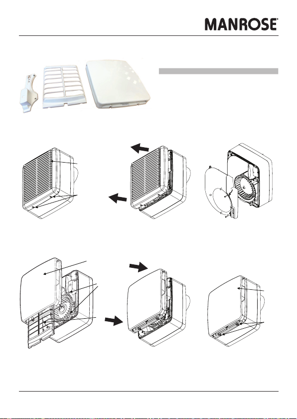
Wall Mounting
1. Remove the front cover assembly by slackening the two screws by two turns
(Fig. 2 & 3). Lift the front cover assembly away from the bottom edge first, then
the top edge.
2. Cut a 115mm diameter hole through the wall, ensuring that there is sufficient
space for the product to be installed and that the filter (Fig. 4) can be removed
for maintenance.
3. Insert the wall sleeve with the larger diameter sleeve on the room-side and
cement the ends into position flush with the wall faces. The wall sleeve should
be angled downwards, away from the fan, to allow any condensation to drain to
the outside.
4. Using the grille’s back plate as a template, mark the fixing hole centres on the
wall. Drill and plug the wall and fix the grille into position. Ensure the louvres are
pointing downwards.
5. Set-up the appropriate speed selection and other features as outlined in SETUP.
6. Remove the small terminal block cover in the top right corner (Fig. 4).
7. Using the fan chassis as a template, carefully sliding the spigot into the wall
liner, mark the fixing hole centres on the wall. Alternatively, the cardboard
fitment can be used as a template.
8. Drill and plug the wall using the fixings provided.
9. Feed the wiring through the hole near the terminal block and secure the fan into
position using the screws provided.
10. Select and follow the appropriate wiring diagram in WIRING CONNECTIONS.
11. Replace the terminal block cover (Fig. 5).
12. Ensure the impeller (Fig. 4) rotates freely.
13. Replace the front cover assembly and tighten the two screws (Fig. 2 & 3).
14. Make sure that all covers are on correctly to ensure the optimum performance
and water ingress protection of the fan.
15. Switch the mains power supply on and check the fan is operating correctly.
Fig. 1
Fig. 3
Fig. 2
Spigot
Flaps (vertical)
Backdraught
Shutter Assembly
Cover Assembly
Cover Screws
Plate Fascia &
Fine Filter Kit
DCT4529
Cover Screws

Installation Instructions Specifications are subject to change without notice Page 5
Cucina 100mm Kitchen Fan
INSTALLATION
A backdraught shutter assembly is supplied. It is packed inside the product
during transport. It is designed to block the duct when the fan is off in order to
prevent cold draughts from outside entering the building. To use it, push it on to
the end of the exhaust spigot (Fig. 1) with the hinges on the flaps vertical. It is
not required when the fan is set up to run continuously.
The Plate Fascia and Fine Filter Kit (DCT4529), shown in Fig. 3 and Fig.4, is an
optional extra kit that can be purchased separately.
Panel or Ceiling Mounting
1. Remove the front cover assembly by slackening the two screws by two
turns (Fig. 2 &3). Lift the front cover assembly away from the bottom edge
first, then the top edge.
2. Cut a 105mm diameter hole through the wall, then suitable screw holes
in the panel, ensuring that there is sufficient space for the product to be
installed and that the filter (Fig. 4) can be removed for maintenance. Either
the cardboard fitment or the fan chassis can be used as a template. The
spigot can be removed temporarily to make it easier. (Fig 1 & 4).
3. Set-up the appropriate speed selection and other features as outlined in
SETUP.
4. Remove the small terminal block cover in the top right corner (Fig. 4).
5. Attach the ducting to the spigot and locate the fan into the hole in the
panel. Feed the wiring through the hole in the chassis next to the terminal
block as you do so (Fig. 5).
6. Secure into position using appropriate fixtures.
7. Select and follow the appropriate wiring diagram in WIRING CONNECTIONS.
8. Replace the terminal block cover (Fig. 5).
9. Ensure the impeller (Fig. 4) rotates freely.
10. Replace the front cover assembly and tighten the two screws (Fig. 2 & 3).
11. Make sure that all covers are on correctly to ensure the optimum
performance and water ingress protection of the fan.
12. Switch the mains power supply on and check the fan is operating correctly.
Fig. 4
Fig. 5
Terminal
Block Cover
Filter
Impeller
Chassis
Assembly
Cover
Assembly
Spigot
PCB Cover
and Screws
Terminal Block
Cable Clamp
Terminal
Block Cover

Installation Instructions Specifications are subject to change without notice Page 6
Cucina 100mm Kitchen Fan
WIRING CONNECTIONS
Use 0.75mm2cable
1. Use the cable clamp provided (Fig. 5).
2. Check all connections have been made correctly and
ensure all terminal connections are securely fastened.
SERVICING AND MAINTENANCE.
1. Following installation, the fan should be inspected and cleaned on a regular basis to ensure there is no build up of dirt or other deposits.
2. If fitted with the metal grease filter, remove the metal grease filter (Fig. 2) from the front cover assembly by gently popping it out from it’s
holding clips on one side of the front cover assembly.
3. Wash the metal grease filter in either a dishwasher or in warm soapy water. Dry before refitting into the cleaned front cover assembly.
4. Clean the front cover assembly by either wiping the inlets and front face with a damp (not dripping wet) cloth or by washing in warm soapy
water. Dry before refitting the metal grease filter and replacing.
5. Turn the power to the fan back on.
The fan has sealed for life bearings, which do not require lubrication.
SETUP
1. SELECTING THE BOOST SPEED *
Link terminal 3 to one of the following:
a. Terminal 1 = Medium (Laundry) speed
c. Terminal 2 = High (Kitchen) speed
* The Ls connection (Fig.8) is optional and if
activated through a standard wall switch, pull cord
switch, PIR or sensor, will switch the fan to either
Medium or High speed depending on which speed
has already been selected.
Pulling the pull cord will cycle the fan through Off,
Trickle, or, depending on which speed has already
been selected, Medium or High.
LOCATING THE FAN
Fig. 8
Fig. 6
Fig. 7
495846 A 0420
Pull Cord
Lamp
Ceiling Junction
Pull Cord
Installation Instructions Specifications are subject to change without notice Page 7
Cucina 100mm Kitchen Fan
Description Order Code
Plate Fascia and Fine Filter Kit DCT4529
FITTING THE PLATE FASCIA AND FINE FILTER KIT
This fascia and filter kit is available as a separately purchased
replacement for the Cucina Kitchen Fan (FAN7201) front grille.
Cover Assembly
Cover Screws
Plate Fascia &
Fine Filter Kit
Cover Screws
1 Slacken the two front cover assembly
screws by two turns
2 Lift the front cover assembly away from the fan
chassis bottom edge first and then the top edge
4 Fit the inner cassette cover supplied onto the
fan chassis with screws provided
6 Tighten the two fascia and filter kit screws
3 Remove the inner cover
Filter
Plate Fascia
Inner
Cassette
Cover
Screws
5 Fit the fascia and filter kit onto the fan chassis
top edge first and then the bottom edge
PUB01600 2008
PLATE FASCIA AND FINE FILTER KIT

Simx Warranty Information
In this warranty:
We means Simx;
You means the consumer of the Goods
Supplier means the authorised distributor or retailer that sold you the Goods in New Zealand or Australia; and
Goods means the Simx product accompanied by this warranty and purchased in New Zealand or Australia.
The benefits provided to you under the following warranty are in addition to any other rights and remedies available
to you under the law:
1. If, during the time from the date of purchase (Warranty Period), there is a defect in the Goods due to improper
workmanship or material, we will replace or repair the Goods without charge. Any replacement product is
warranted only for the time remaining on the original Warranty Period.
2. We are not obliged to replace or repair the Goods under clause 1 if the Goods have been improperly stored,
installed, connected, used, operated, repaired, damaged, abused, tampered with, altered (without our written
approval), or not maintained in accordance with our recommended installation, connection and operating
instructions.
3. We exclude liability for:
a) consequential loss or any other loss or damage caused to property or persons arising from any cause
whatsoever;
b) damage to consumable items such as lamps and starters; and
c) damage arising from normal wear and tear.
4. In order to claim under this warranty you must, within the Warranty Period, return the Goods to the Supplier,
together with the original proof of purchase including the details below:
Supplier Name _____________________________
Date of Purchase _____________________________
Model Number _____________________________
Invoice/Receipt No. _____________________________
5. This warranty does not cover the cost of claiming under the warranty or transporting the Goods to and from the
Supplier.
Our Goods come with guarantees that cannot be excluded under the New Zealand and Australian Consumer Law.
You are entitled to a replacement or refund for a major failure and for compensation for any other reasonably
foreseeable loss or damage. You are also entitled to have the Goods repaired or replaced if the Goods fail to be of
acceptable quality and the failure does not amount to a major failure.
To speak to someone about your Simx product or claiming under this warranty, please contact:
Simx Ltd New Zealand
p: +64 9 259 1660 f: +64 9 259 1661
www.simx.co.nz
This manual suits for next models
1
Table of contents


