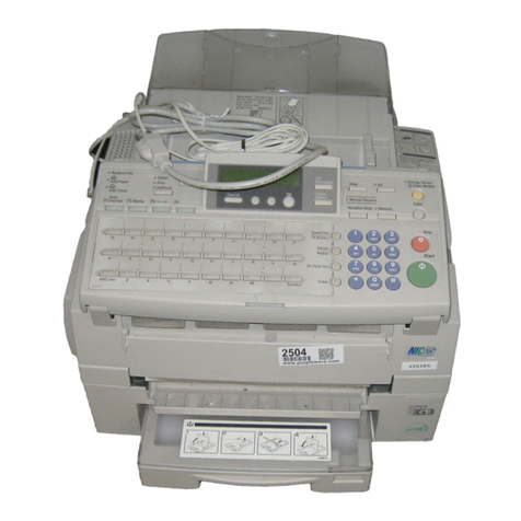
Ricoh Fax 680 MP User manual

IF2
RICOH FAX680MP
SERVICE MANUAL
31 March, 1997
Subject to change.

1
CAUTION
Danger of explosion if battery is incorrectly replaced. Replace only with the same
or equivalent type recommended by the manufacturer.
Dispose of used batteries in accordance with the manufacturer's instructions.
CAUTION: 1) Before attempting any of disassembly or assembly procedure, make
sure of the following:
• Turn off the machine.
• Disconnect the power cord.
• Disconnect the telephone cable(s).
• Disconnect the PC interface cable(s).
• Remove the ink cartridge and place it in the cartridge holder.
NOTE: 1) Do not touch the nozzle section of the ink cartridge. This helps prevent
the nozzles from clogging.
2) Do not touch the wiper blade on the maintenance unit. This also
prevents the nozzles from clogging.
3) Always store an extra cartridge (if unpacked) in the cartridge holder.
4) Ensure the printer engine stops its maintenance operation before
turning off the machine.
5) Ensure that the cartridge is at the head capping position (right end)
before leaving the machine unplugged for long periods.

TABLE OF CONTENTS
1. OVERALL MACHINE INFORMATION............................................1-1
1.1 SPECIFICATIONS..................................................................................... 1-1
1.2 FEATURES................................................................................................ 1-2
1.2.1 FAX FEATURES............................................................................... 1-2
1.2.2 PC INTERFACE FEATURES............................................................ 1-3
1.2.3 SERVICE MODE FEATURES........................................................... 1-3
1.3 COMPONENT LAYOUT............................................................................ 1-4
1.4 OVERALL MACHINE CONTROL.............................................................. 1-6
1.5 DATA PATH............................................................................................... 1-7
1.6 POWER DISTRIBUTION........................................................................... 1-8
2. DETAILED DESCRIPTIONS...........................................................2-1
2.1 SCANNER................................................................................................. 2-1
2.1.1 DOCUMENT FEED MECHANISM.................................................... 2-1
2.1.2 SCANNING....................................................................................... 2-1
2.2 PRINTER................................................................................................... 2-2
2.2.1 PAPER FEED MECHANISM............................................................. 2-2
2.2.2 CARRIAGE DRIVE MECHANISM..................................................... 2-3
2.2.3 INKJET CARTRIDGE....................................................................... 2-3
2.2.4 PRINT HEAD MAINTENANCE UNIT................................................ 2-3
2.2.5 INK LOW CONDITION..................................................................... 2-4
2.2.6 PRINTING FAXES AT 300 DPI RESOLUTION................................ 2-5
2.2.7 PROTOCOL REFERENCE............................................................... 2-6
2.3 PC INTERFACES..........................................................................2-6
2.3.1 PC PRINTER: CENTRONICS INTERFACE........................................... 2-6
2.3.2 PC FAX MODEM: RS232C SERIAL INTERFACE.................................. 2-8
2.4 PCBs........................................................................................................ 2-10
2.4.1 FCU................................................................................................ 2-10
2.4.2 NCU................................................................................................ 2-11
3. INSTALLATION PROCEDURE.......................................................3-1
3.1 PRECAUTIONS......................................................................................... 3-1
3.2 INSTALLING THE MACHINE.................................................................... 3-1
3.3 INITIAL PROGRAMMING.......................................................................... 3-1
3.3.1 PROGRAM AND SETUP ITEMS (SERVICE MODE)........................ 3-1
3.3.2 PROGRAM AND SETUP ITEMS (USER MODE)............................. 3-1
3.4 REMARKS................................................................................................. 3-1
4. SERVICE TABLES..........................................................................4-1
4.1 USER MODE............................................................................................. 4-1
4.2 SERVICE MODE....................................................................................... 4-2
4.2.1 HOW TO ACCESS THE SERVICE FUNCTIONS............................. 4-2
4.2.2 COUNTER DISPLAY (FUNCTION 80)............................................. 4-2
4.2.3 BIT SWITCH PROGRAMMING (FUNCTION 81)............................. 4-2
4.2.4 SYSTEM REPORT (FUNCTION 82)................................................ 4-3
4.2.5 RAM REWRITE (FUNCTION 83)..................................................... 4-4
4.2.6 NCU PARAMETERS (FUNCTION 86).............................................. 4-4
4.2.7 PRINT TEST (FUNCTION 87).......................................................... 4-5
4.2.8 PRINT HEAD POSITION ADJUSTMENT (FUNCTION 88).............. 4-5
4.2.9 ERROR CODE DISPLAY (FUNCTION 89)....................................... 4-5
4.2.10 RAM DATA DUMP LIST (FUNCTION 90)...................................... 4-5
4.2.11 PCL3 FONT LIST (FUNCTION 91)................................................. 4-6
4.2.12 SYSTEM INITIALIZATION.............................................................. 4-6
4.3 BIT SWITCHES......................................................................................... 4-8
4.4 NCU PARAMETERS................................................................................ 4-21
4.5 RAM DEFINITIONS................................................................................. 4-23
5. PREVENTIVE MAINTENANCE......................................................5-1
5.1 PREVENTIVE MAINTENANCE SCHEDULE............................................. 5-1
5.1.1 PM TABLE........................................................................................ 5-1
6.REPLACEMENT AND ADJUSTMENT............................................6-1
6.1 EXTERIOR................................................................................................ 6-2
6.1.1 TOP COVER ASSEMBLY................................................................. 6-2
6.1.2 REAR COVER.................................................................................. 6-5
6.2 PCBS......................................................................................................... 6-6
6.2.1 FCU AND NCU................................................................................. 6-6
6.2.2 PSU AND PCIF................................................................................. 6-8
6.3 SCANNER AND PAPER CASSETTE........................................................ 6-9
6.3.1 MAINTENANCE................................................................................ 6-9
6.3.2 SCANNER AND PAPER CASSETTE ASSEMBLY......................... 6-10
6.4 PRINTER ENGINE.................................................................................. 6-13
6.4.1 MAINTENANCE.............................................................................. 6-13
6.4.2 REPLACEMENT............................................................................. 6-17
7. TROUBLESHOOTING....................................................................7-1
7.1 TROUBLESHOOTNG PROCEDURE........................................................ 7-1
7.1.1 COPY TEST...................................................................................... 7-1
7.2 INK NOZZLE TEST................................................................................... 7-2
7.3 TRANSMISSION TEST............................................................................. 7-3
7.4 POWER ON INITIALIZATION TEST......................................................... 7-4
7.5 LCD DISPLAY ERROR.............................................................................. 7-5
7.6 RECEPTION TEST.................................................................................... 7-6
7.7 PRINT MODULE ERROR.......................................................................... 7-7
7.8 ERROR CODES........................................................................................ 7-8

31 March, 1997 SPECIFICATIONS
1-1
Overall
Information
1. OVERALL MACHINE INFORMATION
1.1 SPECIFICATIONS
Type Desktop Transceiver
Applicable Network PSTN, PABX (Loop Start only)
Connection Direct Coupled
ADF Capacity 20 sheets (using 20 lb. paper)
Document
Width: Max. 220 mm
Effective Scanning Width 216 mm (8.5”)
Scanning Method Contact Image Sensor
Scan Resolution Horizontal: 8 dots/mm
Vertical:
- Standard: 3.85 lines/mm
- Detail: 7.7 lines/mm
Printing Method Ink Jet
Print Resolutions Main Scan: 300 or 150 dpi
Sub Scan: 300 dpi
Effective Printing Width 203 mm (8.0”)
Paper Capacity 150 sheets (using 20 lb. paper)
Printing Paper Size: A4, 8.5 x 11”, 8.5 x 14”
Thickness: 0.08 - 0.12 mm
Communication Speed
(ITU-T #1 Chart, MR
compression, TTI off)
Transmission: 17 ± 1 s (Memorytx)
Reception: 17 ± 1 s (Memoryrx)
46 ± 4 s (Directrx)
Protocol T.30
Important:Non-standard signals, NSF and NSS, are
not compatible with existingRicoh fax machines.
Coding Scheme MH, MR
Modem Speed 9600/7200/4800/2400bps
Modulation V.29 (QAM), V27ter (PHM), V.21 (FM)
Memory Capacity
(ITU-T #1 Chart) ECM: 128kB
SAF (standard): 384kB (18 pages)
SAF (with optional 1MB): 1.4 MB (58 pages)
Power Consumption Standby: 17W (18W max.)
Transmission: 25W (28.5W max.)
Reception: 19W (21W max.)
Copy: 27W (31W max.)
Operating Environment Temperature: 17 - 28°C (63 - 82°F)
Humidity: 40 - 70 %Rh
Dimensions Width: 363 mm
Length: 285 mm
Height: 173 mm
(Excluding trays, supplies, and optional units)
Weight 7.1 kg (Excluding trays, supplies, and optional units)

FEATURES 31 March, 1997
1-2
1.2 FEATURES
Please refer to the Operator’s Manual for the available user features and their
details. The following table explains the chief differences from the existing ink-jet
fax, model IFO.
1.2.1 FAX FEATURES
FEATURES IF2
(THIS MODEL) IFO
(EXISTING
MODEL)
Authorized reception Not available Standard
Batch transmission Not available Optional
Chain dialing Not available Standard
Confidential transmission/reception Not available Optional
Direct fax number entry Not available Standard
Forwarding Not available Standard
Number of Quick Dial keys 10 10
Number of Speed Dials 50 50
Number of dialing groups 5 groups 3 groups
Keystroke programs Not available Standard
Communication features using ID code
(e.g., Secured polling, closed network) Available
(not compatible
with existing
models)
Available
(not compatible
with IF2)
Tonal signal transmission Not available Standard
Transmission deadline (TRD) Not available Optional
Voice Request Standard Not available
Page separation mark Not available Standard
Memory capacity display when there is no file
in the SAF memory 99% 100%
Compression MH and MR MH, MR, MMR,
EFC, and SSC
SAF memory backup Not available Standard
(1 hour)

31 March, 1997 FEATURES
1-3
Overall
Information
1.2.2 PC INTERFACE FEATURES
PC INTERFACE FEATURES IF2
(THIS MODEL) IFO
(EXISTING
MODEL)
Parallel interface Bi-Centronics Centronics
Printer Emulation HP PCL3 and IBM
PPDS BJ and LQ
Serial interface RS232C
(9 pins) RS232C
(25 pins)
PC fax specification Standard
(EIA Class 1) Optional
(EIA Class 2)
1.2.3 SERVICE MODE FEATURES
SERVICE MODE FEATURES IF2
(THIS MODEL) IFO
(EXISTING
MODEL)
Back-to-back test Not available Available
Bit switches Available Available
Buzzer test, DTMF tone test, Operation panel
test, and Modem test Not available Available
Communication parameter display Available Available
Counter check Available Available
Country code Available Available
Error code display Available Available
File transfer Not available Available
Line error mark Not available Available
NCU parameters Available Available
Printer mechanism test Not available Available
Printer test patterns Available Available
Protocol dump list Not available Available
RAM display/rewrite Available Available
RAM dump Available Available
RAM test Available in user
mode Available
Serial number/ Service station number
programming Not available Available
Service monitor report Not available Available
Software upload/download Not available Available
SRAM data download Not available Available
System parameter list Available Available
Technical data on Journal Not available Available
User data transfer using RDS Not available Available
RAM read/write using RDS Available
(300 bps) Available
(9,600 bps)

COMPONENT LAYOUT 31 March, 1997
1-4
1.3 COMPONENT LAYOUT
H905V001.cdr
H905V002.cdr
1
2
3
456
7
8
9
10
11 12
13
14
15

31 March, 1997 COMPONENT LAYOUT
1-5
Overall
Information
No. Description Function
1Tx Motor Drives the document feed mechanism.
2CIS (Contact Image
Sensor) Scans the document.
3Paper End Sensor
(SB4) Detects paper in the cassette.
4Document Sensor
(SB1) Detects when a document is placed in the document
feeder.
5Scan Line Sensor
(SB2) Detects when a document arrives at the scan start
position.
6Rx Motor Drives the paper feed mechanism.
7Carriage Drive Motor Drives the print carriage.
8Maintenance Motor Drives the print head cleaning mechanism.
9Carriage Position
Sensor Generates a pulse signal to detect the carriage location.
10 PSU Supplies dc voltage to the FCU.
11 PC I/F Interfaces to a host computer throughBi-Centronics
parallel and RS232C (9 pins) serial interfaces.
12 OPU Interfaces to operators through keys and an LCD panel.
13 FCU Controls fax and printer engines.
14 Registration Sensor
(SB5) Detects printing paper at the registration position.
15 NCU Interfaces to an analog telephone network.

OVERALL MACHINE CONTROL 31 March, 1997
1-6
1.4 OVERALL MACHINE CONTROL
The TC35167F fax engine controls the fax features, while the Motorola M68000
cpu controls the PC printer features. The FOX2 chip controls the printer
mechanisms and the parallel port.
The components are described in more detail in section 2.4.
FCU
PCIF
M68000
FAX ROM
(128 kB)
Printer ROM
(128 kB) DRAM
(128 kB)
SB4
OPU
SB2SB1
DRAM
(512 kB) DRAM
(1 MB) SRAM
(8 kB)
CIS Driver Speaker
AFE NCU
ADDRESS/DATA BUS
ADDRESS/DATA BUS
Driver
Driver
Driver
Carriage
Motor
Maintenance
Motor
Rx Motor
Inkjet Head
SB5
TC35167F
FOX2
Serial
Interface
(DSUB 9 pin)
Centronics
Interface
(36 pin) Buffer
Buffer
Driver
Driver Tx Motor
H905V010.VSD

31 March, 1997 DATA PATH
1-7
Overall
Information
1.5 DATA PATH
FCU
FCU
SAF ECM/L.B.
CIS TC35167F NCU
SAF ECM/L.B.
TC35167F
FOX2
NCU
Printer
Engine
FCU
L.B.
Serial
I/F TC35167F NCU
FCU
FOX2/M68000
Centronics
I/F
Printer
Engine
FCU
SAF
TC35167F
FOX2
Printer
Engine
CIS
Fax Tx
Fax Rx
PC-Fax Tx/Rx
Printer
Copy
H905V012.VSD

POWER DISTRIBUTION 31 March, 1997
1-8
1.6 POWER DISTRIBUTION
FCU
SB4
OPU
SB2
SB1 CIS
NCU
Carriage
Motor Maintenance
Motor Rx Motor
Inkjet Head
Tx Motor
PSU
+5V
DC/DC
- 12V
+24V
+5V -12V +24V +12V
+5V
+24V
+5V
+24V
+5V
+5V
+24V
+5V
+5V
+24V
+5V
+24V
+24V
+24V
H905V011.VSD

31 March, 1997 SCANNER
2-1
Detailed
Descriptions
2. DETAILED DESCRIPTIONS
2.1 SCANNER
2.1.1 DOCUMENT FEED MECHANISM
The feed roller [A] feeds the document into scanner, and the separation pad [B]
prevents more than one sheet of the document from feeding.
When the document reaches the scan line, the Tx motor stops until the machine is
ready for scanning.
While scanning, the CIS roller [C] and the R2 rollers [D] feed the original.
NOTE: The pressure applied to the separation plate is adjustable. Refer to
section 6.1.1.
2.1.2 SCANNING
Every time the machine scans a document, the CIS (Contact Image Sensor),
scans the CIS roller (a white roller located on the CIS) before scanning the first
page, to get a base white waveform. This whitewaveform is used for the shading
correction that is used while scanning all pages of the document. So, if the CIS
roller becomes dirty, the scanned image becomes darker.
NOTE: The cleaning procedure for the CIS roller is explained in section 6.3.1,
as well as in the operator’s manual.
H905D001.cdr
[A] [B] [C]
[D]

PRINTER 31 March, 1997
2-2
2.2 PRINTER
2.2.1 PAPER FEED MECHANISM
The Rx motor [A] in the printer engine drives all the paper feed components.
At the start of printing, the Rx motor rotates clockwise to move the gear arm [B] to
drive the paper feed roller [C]. The separation hooks [D] prevent more than one
sheet of paper from being fed into the printer engine.
When the paper reaches the registration roller [E], the motor reverses to drive
registration and feed-out rollers. After printing, the motor rotates clockwise again
to eject the paper from the printer using the ejector [F], and to move the gear arm
[B] to the standby position.
The paper end sensor [G] detects paper end.
H905D002.cdr
H905D003.cdr
[A]
[B]
[C]
[D]
[E] [F]
[B]
[G]

31 March, 1997 PRINTER
2-3
Detailed
Descriptions
2.2.2 CARRIAGE DRIVE MECHANISM
The carriage drive motor [A] drives the print head carriage [B] through the belt [C].
The sensor [D], located under the carriage generates a pulse signal while it moves
along the encoder [E] (a thin metal plate with many slits), so that the printer engine
can detect the horizontal location of the carriage.
2.2.3 INKJET CARTRIDGE
The inkjet cartridge uses a thermal ink jet
mechanism. When the print head receives print
signals, the heating element [A] located by ink
chamber [B] generates a tiny bubble inside the
chamber to eject an ink drop out of it.
The nozzles are arranged in a straight line at
intervals of 300 inch. The black print head has 58
nozzles, of which 52 nozzles are for printing. The
color cartridge has 48 nozzles, 16 for each color.
2.2.4 PRINT HEAD MAINTENANCE UNIT
When the print head needs cleaning, the
maintenance motor [A] moves the head cap [B] up
and down towards and away from the print head.
This action sucks waste ink out of the nozzles on
the print head.
Then, the maintenance motor moves up the wiper
blade [C], and the carriage moves right and left to
wipe the waste ink off the print head.
After these maintenance actions have finished, the
print head stays at the default position, and the
cap [B] caps the head.
H905d004.cdr H905d005.cdr
Ink
H905D006.vsd
H905D007.cdr
[A]
[B]
[A]
[B]
[C]
[D]
[E]
[A]
[B]
[C]

PRINTER 31 March, 1997
2-4
2.2.5 INK LOW CONDITION
The machine does not have an ink end detection mechanism, but it can detect an
“ink low” condition.
The printer engine counts the number of ink drops to calculate the cartridge
replacement timing. When the machine determines that approximately 85% of the
ink has been used, the machine displays the “INK LOW” message.
When a new cartridge is installed, the machine asks the user whether the
cartridge is new or used. If the user selects “Yes” to the “NEW INK Y/N?”
message, the machine initializes the counter. If the user selects “No” to the
message, the machine continues counting ink drops without initializing.
Therefore, the accuracy of the counter is quite important. If the user initializes the
counter accidentally, ink-end may only be determined by looking at the print
output. (This may easily happen when the user changes the cartridge from black to
color and vise versa.)
NOTE: 1) The printer engine has separate counters for black cartridge and color
cartridge. Their internal circuits are different, and the machine detects
the difference to determine which counter is present.
2) The counters, CURRENT-0, 1 and 2, listed on the system parameter list
are not used for detecting ink-low condition. These are just the latest
three records of ink cartridge replacements.

31 March, 1997 PRINTER
2-5
Detailed
Descriptions
2.2.6 PRINTING FAXES AT 300 DPI RESOLUTION
To print received fax data in 300 x 300 dpi resolution, the machine converts the
resolution as shown in the diagram. After conversion, the machine gets 2592 dots
(1728 x 1.5 dots). However, the number of dots required for printing is 2400 (= 8” x
300 dpi). So, the machine reduces the print data using the reduction ratio specified
by Function 45. The default reduction ratio is 93% (≈2400/2592).
Cross Reference
Process used for converting main-scan resolution (horizontal) - Bit 5 of bit switch
C
Process used for converting sub-scan resolution (vertical) - Bit 6 of bit switch C
For best results, keep both settings at “AND”.
1/8 mm
1/7.7 mm
Line Pairs
Line Pairs
Dot Pairs
Dot Pairs
Dot Pairs
300 dpi
300 dpi
Horizontal: AND
Vertical:AND Horizontal: OR
Vertical:OR
Horizontal: AND
Vertical:OR
Horizontal: OR
Vertical:AND
Horizontal Direction Process
AND
OR : Generated Black Dot
H905D010.vsd

PC INTERFACES 31 March, 1997
2-6
2.2.7 PROTOCOL REFERENCE
DIRECT RECEPTION IN LOW MEMORY CONDITIONS
When the machine detects an incoming fax call while in the following conditions,
the machine receives the fax in direct reception mode (the data goes straight to
the printer without storage in memory).
• Available SAF memory is lower than 35% (without optional memory)
• Available SAF memory is lower than 10% (with optional memory)
In these cases, if the machine is not printing, the machine answers the call using
DIS/NSF signals with “I/O rate = 20 ms/line” and “modem rate = 4,800 bps”
parameters. If the machine is printing, it does not answer the call.
NOTE: 1) In Germany, the machine does not answer a call in the above memory
conditions.
2) If the machine’s available memory is above the threshold, the machine
receives the fax message in memory reception mode.
3) Even if the amount of memory falls below the threshold while receiving
a fax message, the machine continues memory reception.
2.3 PC INTERFACES
2.3.1 PC PRINTER: CENTRONICS INTERFACE
The machine can function as a PCL3 printer or an HP DeskJet500C compatible
color printer, using the built-in Bi-Centronics interface. Refer to the Operator’s
Manual for printer installation and set up.
PRINTER SPECIFICATIONS
Refer to the Operator’s Manual and the printer driver help file for the specifications
not listed here.
Emulation Modes PCL3 (HPDeskJet 500)
PPDS (IBMProprinter X24E)
HP DeskJet 500C (Color)
Hex Dump
Print Speed 2 ppm (Draft mode)
Print Margins Top: 3+/- 1.5 mm
Bottom: 4.5 +/- 1.5 mm
Left: 2.5 +/- 1 mm (A4), 5.5 +/- 1 mm (LT, LG)
Right: 4 +/- 1 mm (A4), 7 +/- 1 mm (LT, LG)
Interface Bi-Centronics (IEEE 1284 compatible)
Cable IEEE 1284 compatible, not longer than 1.8 m.
Built-in Fonts Letter Gothic, Courier, CG Times (Scaleable), and
Univers (Scaleable)

31 March, 1997 PC INTERFACES
2-7
Detailed
Descriptions
Character Sets PCL3 Emulation Mode
ECMA94, PC8, PC8 Danish Norwegian, PC 850,
Roman 8, HP Legal, ISO2 IRV, ISO4 UK, ISO6 ASCII,
ISO10 Swedish, ISO11 Swedish Names, ISO14 JIS
ASCII, ISO15 Italian, ISO16 Portuguese, ISO17
Spanish, ISO21 German, ISO60 Norwegian 1, ISO61
Norwegian 2, and ISO69 French
PPDS
Code Page 437 and 850
BLACK & WHITE PRINTING
When a mono cartridge is installed, the machine prints both fax messages and
print data.
If the machine receives a print request from a host computer while receiving a fax
message, the computer receives a printer busy signal. In this case, the Print
command on the PC must be selected again after the machine finishes printing the
fax.
If the machine receives a fax message while printing a data from a host computer,
the machine receives the message into SAF memory. After the machine finishes
printing, the fax message prints automatically.
COLOR PRINTING
When a color cartridge is installed, the machine cannot print any fax messages or
reports.
If the machine receives a fax message while a color cartridge is installed, the
machine receives the message into SAF memory and displays “CHANGE INK TO
MONO”. After theMono cartridge is installed, the machine prints the message
automatically.
NOTE: When “CHANGE INK TO MONO” appears, the carriage can be moved
to the replacement position just by opening the top cover.

PC INTERFACES 31 March, 1997
2-8
2.3.2 PC FAX MODEM: RS232C SERIAL INTERFACE
The machine can function as an EIA Class 1 fax modem, using the built-in serial
interface (D-SUB 9 pins). Refer to the Operator’s Manual for how to install and set
up the machine as a fax modem.
NOTE: The serial interface is not available in some countries.
SPECIFICATIONS
Standard EIA/TIA Class 1
Fax Communication Speed 9600/7200/4800/2400 bps
Host Interface Speed 19200 bps (maximum)
Flow Control XON/XOFF
Interface Cable Straight-through, double-shielded serial RS232-C cable
with either DB9-pin and DB25-socket connectors, or
DB9-pin and DB9-socket connectors
NOTE: The machine does not come with a serial cable.
CABLE PIN ASSIGNMENT
CLASS 1 INTERFACE
The EIA/TIA Class 1 PC-Fax interface lets the fax application running on the host
computer control all of the T.4, T.6 and T.30 procedures. So, the machine cannot
log pc-fax communications on the TCR.
DB25
(Male) DB9 or 25
(Female)
Max. 3 meters
2
3
7
2
3
7
RXD
GND
TXD
TXD
GND
RXD
Pin#Pin#
H905D012.VSD
Other manuals for Fax 680 MP
1
Table of contents
Other Ricoh Fax Machine manuals

Ricoh
Ricoh FAX2500L User manual

Ricoh
Ricoh B383 User manual

Ricoh
Ricoh FT5233 User manual

Ricoh
Ricoh FAX3800L User manual

Ricoh
Ricoh FAX75 User manual

Ricoh
Ricoh 3900L User manual

Ricoh
Ricoh 1195L Operating and maintenance manual

Ricoh
Ricoh infotec 3671F User manual

Ricoh
Ricoh LASER FACSIMILE User manual

Ricoh
Ricoh FAX4430L User manual

Ricoh
Ricoh Aficio FAX5000L User manual

Ricoh
Ricoh SMFC210M SecureFax User manual

Ricoh
Ricoh 4430NF User manual

Ricoh
Ricoh FAX4500L User manual

Ricoh
Ricoh Fax22 User manual

Ricoh
Ricoh FAX 2900Li User manual

Ricoh
Ricoh FAX07 Quick start guide

Ricoh
Ricoh FAX5510L Operating instructions

Ricoh
Ricoh Fax 2210L User manual

Ricoh
Ricoh fax4700l User manual