Manson Engineering Industrial PVC-7830 User manual

PV Charge Controller
PVC - 7830 / 7840
User's Manual
LCD Display (Monitoring Screen with back light)
Precautions:
1. Before using the PVC PV Charge Controller, read all instructions and cautionary markings on the
controller, solar panels and batteries.
2. This PV Charge Controller is designed for indoor use for 12V or 24V solar system, do not exceed the given
power rating of charge and load given in the specifications.
3. Do not attempt to repair the controller. Incorrect re-assembly may result in a risk of electric shock or fire.
4. PV panels produce power when exposed to light after disconnection keep the terminals well isolated. Cover
them with opaque material such as clothe before installation.
5. To reduce risk of electric shock, disconnect all wiring before attempting any maintenance or cleaning of the
PV system.
6. Working in the vicinity of lead acid batteries is dangerous as they produce explosive gases so make sure no
naked fire or spark is present when working near batteries. Sufficient ventilation must be provided to the
battery compartment. Eye protection should be used.
7. Be extra cautious to reduce the possibility of dropping a metal tool onto batteries. It may spark or short-circuit
batteries or other electrical parts that may cause explosion.
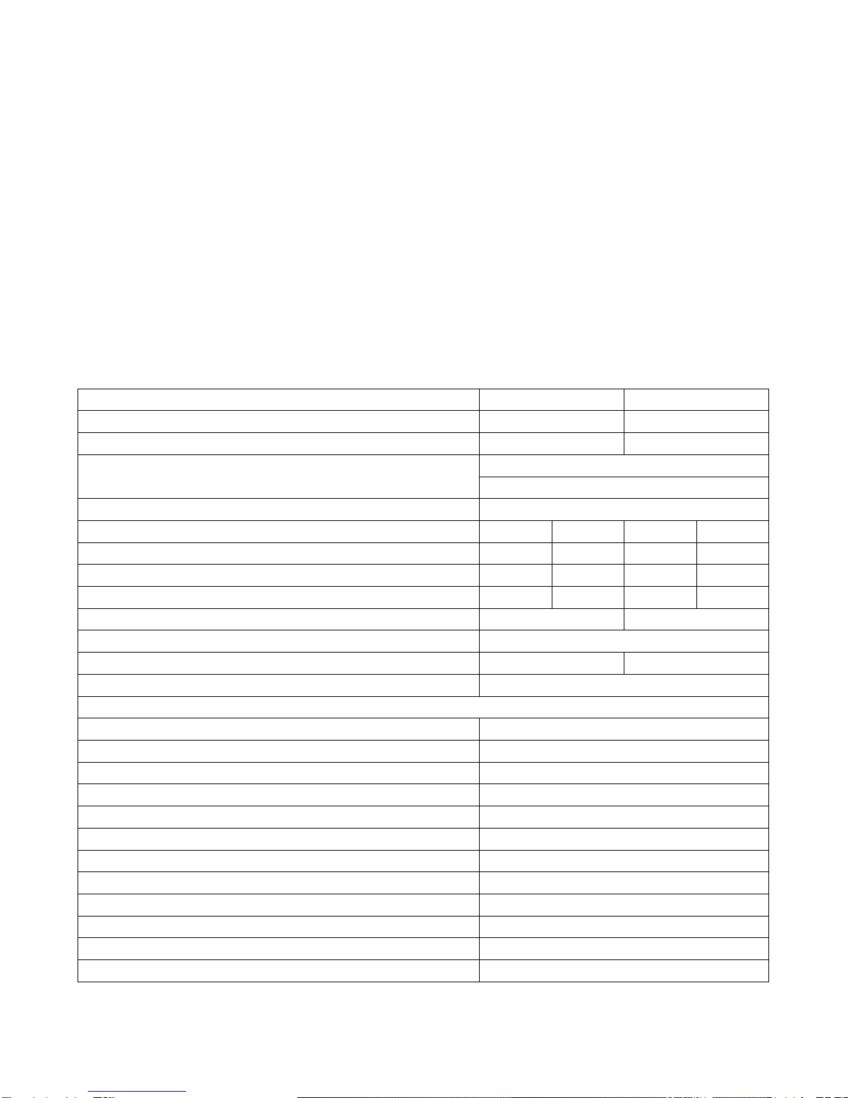
Specifications
12V Batt. System
24V Batt. System
System Battery Operation Range
4-16V nominal 12V
8-32V nominal 24V
Max. Continuous PV Open Circuit Voltage
30V
60V
Max. Charging Current
PVC-7830 30A
PVC-7840 40A
Max. Output Current at Load Terminal
20A
Battery type
Bulk
Float
Bulk
Float
WET
14.7V
13.4V
29.4V
26.8V
Sealed
14.4V
13.6V
28.8V
27.2V
LifeO4
14.6V
14.4V
29.2V
28.8V
Battery Low Voltage Disconnect (LVD)
11.5V
23V
LVD Delay Time
5 minutes
Battery Low Voltage Reconnect (LVR)
12.8V
25.6V
LVR Delay Time
5 minutes
Protections
Over Temperature Protection (Self Recoverable)
Yes
Over Voltage Protection at PV Terminal
Yes
Over Voltage Protection at Battery Terminal
Yes
Over Charge Current Protection (Self Recoverable)
Yes
Over Current Protection at Load Terminal (Self Recoverable)
Yes
Battery Reverse Polarity Protection (Self Recoverable)
Yes
PV Reverse Polarity Protection (Self Recoverable)
Yes
USB Charging Port forApple iPad, iPhone and Tablets Smart Phone
5VDC 1A Max.
Remote Temperature Sensor
Yes
Operation Ambient Temperature Range
-10 to +50°C
Dimension (L x W x H)
150x200x64mm 5.9x7.9x2.5inch
Weight
1.1kg 2.5lbs

Introduction
The PVC is designed for use with all types of solar panels, lead acid batteries and LiFePo4 batteries for 12 and 24
V solar system.
1. The LCD with control back light displays critical live information of PV charging voltage, current and battery
voltage, charge status and load condition in one screen.
2. There are 15 parameters that can be viewed, set or adjusted using the 4 buttons.
3. Three Stage charging plus Equalization Charge for Wet battery .PWM charging for Absorption and Float
stages.
4. Selection for no float charge is available.
5. Adjustable voltage and delay time for Bulk, Float, LVD and LVR.
6. The Remote Control for trigger or on-off control of external devices, (e.g. Alarm, relay, on/off of charger or
inverter etc.) to operate in the same time as the load control programs and LVD / LVR.
7. Two Night Light Load and Two Day Light Load Programs.
8. One adjustable PV voltage for Sun Rise and one for Sun Set reference time line.
9. One USB charging port for Apple or Android device
10. Remote battery voltage sensing and optional remote temperature sensor.

Control and Indicator
1. LCD Display with back light control
2. Up and Down Buttons
3. Enter / Confirm Button
4. Menu Button
5. PV Reverse Polarity Fault
6. Battery Reverse Polarity Fault
7. Remote Control RJ-45 Socket
8. USB Charge Port (5V 1A)
9. Load Terminal
10. Battery Terminal
11. PV Panel Terminal
12. Battery Remote Temperature Sensor Terminal
13. Battery Remote Voltage Sensor Terminal

Connection
Remote Signal Terminal
The PV controller has an optional remote signal output terminal which can:
1. Used to control the ON/OFF operation of equipment such as inverter hooked up to the battery bank to
operate along with the night-light mode program and share the safeguard function such as low battery
disconnect and reconnect.
2. Extend battery status LED to allow remote monitoring Battery bank status.
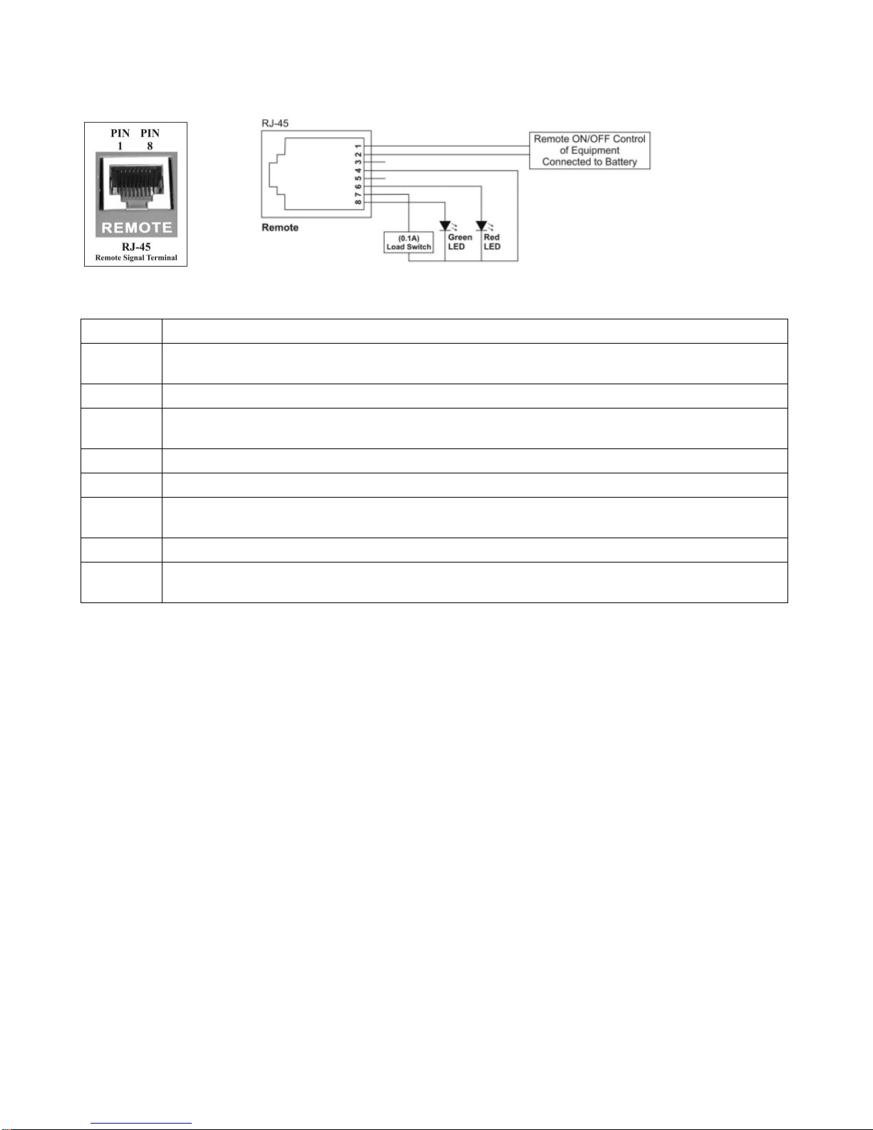
RJ-45 Pin Configuration:
Pin assignment
Pin
Function description
Pin 1
Relay (Normal Open mode) @Max. 0.2A
Synchronized with the LOAD Positive Terminal output On/Off signal
Pin 2
Relay Common @Max. 0.2A
Pin 3
Relay (Normal Close mode) @Max. 0.2A
Opposite to the LOAD Positive Terminal output On/Off signal
Pin 4
GND
Pin 5
NC
Pin 6
RED LED signal
If@Max. 30mA, Vf@1.8-2.4V
Pin 7
LOAD Positive Terminal signal (12V @Max. 0.1A)
Pin 8
GREEN LED signal
If@Max. 30mA, Vf@2-2.6V

Operation
Using the 4 buttons:
Always push the [menu] button until the display shows the charging status first, then proceed to push the
[Up]button for Ah of the last 7 days or push the [Down] button to check the setting status of the load terminal and
other system settings.
button - One press will display critical live information of the PV system,
another press will show the 15 parameter menu.
The and buttons are for moving the cursor up and down to reveal all the parameters.
These two buttons also select YES or No status of some parameter.
The buttons has two functions: to enter into the selected parameter for new setting and or to confirm the new
setting, both functions are done by long press of about 5 seconds on release the parameter should flicker.
Once a parameter is activated, it flickers, press the or button to get to the desired setting value or status
then a long press at the again until the new setting stop flickering to confirm the new setting is done.
Setting system voltage parameters
First time installation, connect only the battery to the PVC controller check and adjust the parameters then
connect the PV and load to complete the whole installation.
When battery terminals are connected, the LCD display will show
You can confirm the 12V setting by long press of the or press the to move the cursor to 24V followed by
long press of .
If no selection is made within one minute, it will revert back to the last selected system voltage.

Viewing and Checking of System parameters
Press button once or twice for the display of parameters, press or button to move the cursor
displaying the various parameters as below:
1. Battery Type: Sealed /Wet/ LiFePo4
2. Bulk Voltage:
3. Float Voltage:
4. Time Absorption:
5. LVD Low Voltage Disconnect:
6. T_LVD Time Delay before disconnect:
7. LVR Low Voltage Reconnect:
8. Load Control: Two Programmable Loads for day and two for Night
9. Equ. Equalization Charge: Manual / Auto / Off
10. BL: Back light of display on-time
11. Clear AH: Yes or No
12. USB: charge port On or Off /
13. Night V: setting of solar voltage to define Sun Set and start of night (to off set city light)
14. Float Charge: Y or N: In no Float Charge setting, Controller recharge again when battery voltage drops
below the set Float Voltage for more than 5 minutes.
15. Default: Y or N: Yes will reset all the parameter settings to factory default values.
The programming steps for the above 15 parameters (except 8. Load Control )
Follow the same 5 logical steps:
1. Short presses of button to the list of parameters
2. Short presses of or button to move the cursor to the desired parameter.
3. Long press (5 second) then release to activate the parameter. (flickering)
4. Short presses of or button to change the setting value.
5. Long press (5 second) then release to confirm new setting. (no flickering)
The Load Terminal (Menu 8: Load control)
Caution:
The voltage at the load terminal changes with the voltage of the battery terminal, under LOAD OUT or Day Light
Mode the voltage can be as high as the absorption charge voltage or equalization voltage.
Load Control Programming
[ ] LOAD OUT => Always on Mode
[ ] NLM => Night Light Mode
[ ] DLM => Day Light Mode
Save & Exit => long press ready to save entry and exit from Load Control Programming.
Remark:
The programming procedure is quite different from the other 14 system parameters programming as given in the
preceding section 3 and 4.
A tick in the box [ ] indicates the mode has been programmed, it is possible to have tick in NLM and DLM at the
same time .When no tick is in any of the boxes, no load program has been set.
Only NLM and DLM can be further programmed and once LOAD OUT has been set, you cannot set either NLM or
DLM.

Long press then release to activate LOAD CTRL
Any one of the above four can be flickering
Short presses of either or to the desired setting which will flick
Short presses of will put a tick or take out a tick from the box.
Let us use NLM (Night Light Mode) as an example:
When NLM flickers, long press until a new screen appears, similar to the following.
The first setting above the bar flickers, each press increases time by 0.5 hr and decrease by 0.5 hr.
Press makes the first lower setting flickers, use or to adjust the timer.
Press to program the second timer similarly
Long Press at the last setting of second timer will exit to the first load control menu as shown below diagram
to be added
Press button to {Save & Exit } and Press to exit to the main menu to confirm the setting.
There are two timer settings first one uses set sun as reference (start time)
Light or load is on at 2 hours after sun set
Light or load is off at 3.5 hours after sun set
So light will be on for (3.5 -2 = 1.5 hours)
The Second On-Off timer setting uses Sun Rise as reference (start time)
Light is on 2 hours before Sun Rise
Light is off 0.5 hour (30 minutes) before Sun Rise
Light will be on for (2 -0.5 = 1.5 hour)
This manual suits for next models
1
Table of contents
Other Manson Engineering Industrial Controllers manuals

Manson Engineering Industrial
Manson Engineering Industrial SBC-7230 User manual

Manson Engineering Industrial
Manson Engineering Industrial PVC-7820 User manual

Manson Engineering Industrial
Manson Engineering Industrial SBC-7208 User manual

Manson Engineering Industrial
Manson Engineering Industrial SBC-7100 Series User manual

Manson Engineering Industrial
Manson Engineering Industrial MP-3722 User manual


