Manson Engineering Industrial DPD Series User manual

DPD series
REV.1.6 6/2004
LABORATORY GRADE
DUAL TRACKING TRIPLE OUTPUT
DC REGULATED POWER SUPPLIES
7673-1850-0000

CONTENTS
1.) Introduction P.1
2.) Safety Instruction and Precautions P.1
3.) Precautions P.1
4.) Specifications P.2 , P.3
5.) Controls and Indicators of Front Panel P.4
6.) Controls and Indicators of Rear Panel P.4
7.) Operation Procedure P.5 , P.6
7.1 Correct Input Voltage Selection
7.2 Normal Mode Operation
7.3 Series Mode Operation
7.4 Parallel Mode Operation
7.5 Auxiliary Power Output

1. Introduction
The DPD series are intended for engineers who need a wide range of voltage and current to cover their
applications with ease.
MODEL DUAL TRACKING OUTPUTS THIRD OUTPUT
DPD1850 0~18V x 2 0~5A x 2 1.5~6V 5A
DPD3030 0~30V x 2 0~3A x 2 1.5~6V 5A
DPD6015 0~60V x 2 0~1.5A x 2 1.5~6V 5A
Double the voltage or current can be obtained in series mode or parallel mode respectively with the two
independent and fully isolated outputs. The master unit controls the combined outputs with ease.
In the normal output mode, each operates independently with its own current and voltage control and
LED meters. Constant Current, CC and Constant Voltage, CV with automatic cross over are effective in
series and parallel mode as well.
To offer maximum versatility for electronic engineer, the DPD series have a third separate 5A, 1.5~6V
adjustable output for new and old logic circuits such as Fast & LS TTL.
The current trend is moving from 5V to 3.3V and lower for new logic circuit designs.
Furthermore, the current and voltage level of this third output can be read in the Master's LED volt and
amp LED meters as well.
The voltage and current adjustment for both the Master and Slave outputs are of high precision wire-
wound potentiometer. Four 4-Digit LED high resolution meters are used.
The specifications of the line , load regulation and ripple and noise limits are comparable to if not
better than the reputable make in the industry.
2. SAFETY INSTRUCTIONS AND PRECAUTIONS
1. Do not use this apparatus near water.
2. Clean only with dry cloth.
3. Do not block any ventilation openings.
4. Do not install unit near any heat source or heating emitting devices.
5. Prevent the power cord from being walked on or pinched.
6. Unplug this unit during lighting storms or when unused for long periods of time.
3. PRECAUTIONS
1. The unit must be used within its specified range.
The rated input voltages can be found on the rating label at the back the unit.
Before plugging into the AC supply, check with the rating label.
2. Refer all servicing to qualified service personnel.
Warning !
Model DPD-3030 and DPD-6015, the maximum output voltage is OVER 60 Vdc.
It may be hazardous to touch metal part of the output terminals.
User must avoid touch live metal part of the output terminals.
P.1

4. SPECIFICATIONS
MODEL
Master / Slave Independent Output
Output Voltage Range
Load Voltage Regulation ( 0-100% Load )
Line Regulation ( 10% Variation )
Ripple & Noise (RMS)
Output Current Range
Load Current Regulation
Line Current Regulation
Ripple Current
Recovery Time
Series Mode Output
Output Voltage Range
Output Current Range
Load Regulation
Tracking Error
Parallel Mode Output
Output Voltage Range
Output Current Range
Load Regulation
Tracking Error
Auxillary Output
Output Voltage Range
Rated Output Current
Load Voltage Regulation ( 0-100% Load )
Line Regulation ( 10% Variation )
Ripple & Noise ( RMS )
DPD - 1850
0 - 18VDC
0 - 5ADC
0 - 36VDC
0 - 5ADC
0 - 18VDC
0 - 10ADC
DPD - 3030
0 - 30VDC
0.01% + 3mV ( Ignoring ohmic contact of binding posts )
0.01% + 3mV
1mV
0 - 3ADC
0.2% + 3mA
0.2% + 3mA
3mA R.M.S.
100 second
0 - 60VDC
0 - 3ADC
300mV
0.5% +10mV
0 - 30VDC
0 - 6ADC
1.5 - 6VDC
5A
10mV ( Ignoring ohmic contact of binding posts )
5mV
1mVrms
DPD - 6015
0 - 60VDC
0 - 1.5ADC
0 - 120VDC
0 - 1.5ADC
0 - 60VDC
0 - 3ADC
P.2
300mV
0.5% +10mV

General
Selectable Input Voltage : - 110VAC / 120VAC / 230VAC / 240VAC 10%,
- Frequency 50 / 60 Hz
Meters & Displays : - C.C. & C.V. Indicators
- 4-Digit LED Meters
- Voltmeter Accuracy 0.5% +2 Counts
- Voltmeter Resolution 10mV
- Ammeter Accuracy 0.5% +2 Counts
- Ammeter Resolution 1mA
Green LED : - Master's Voltmeter & Ammeter switched to read Auxilliary output
Red LED : - Auxilliary Output Overload indication
Insulation : * Withstanding test ( 60 second 1mA ) 1500V :-
- Power cord to housing
- Power cord to output terminal.
* Withstanding test ( 60 second 10mA ) 500V :-
- Output terminal to housing.
* Insulation Resistance at 500VDC :-
- Housing to power cord 30 mega Ohm
- Housing to output terminal 30 mega Ohm
Cooling System : - Fan Cool
Protection : - Overload
- Over Temperature
- Short Current
- Reverse Polarity
- Input Socket with 8A Fuse
EMC & Electrical Safety : - CE - EMC: EN 55011 , CE - LVD: EN 61010
Dimension : - 379 x 280 x 135 mm
Weight : - 12Kgs
~ SPECIFICATIONS ARE SUBJECT TO CHANGE WITHOUT NOTICE ~
P.3

5. Controls and Indicators of Front Panel
1. Retractible metal handle. 14. Output Voltage adjust knob (wire-wound type) of
2. DC Voltmeter of Slave Power Supply. Master Power Supply.
3. DC Ammeter of Slave Power Supply. 15. Output Current adjust knob (wire-wound type) of
4. Constant Current Mode ( CC) Indicator. Master Power Supply.
5. Constant Voltage Mode (CV) Indicator. 16. GND Terminal ( ) Green. Chassis ground terminal.
6. DC Voltmeter of Master Power Supply and Auxiliary 17. Power On/Off switch, power on with light.
Power Supply. 18. Mode Selector Switch.
7. DC Ammeter of Master Power Supply and Auxiliary 19. Output Terminal Positive ( ) of Auxiliary Power
Power Supply. Supply.
8. Green LED indicator showing Master's meter 20. Output Terminal Negative ( ) of Auxiliary Power
readings for Auxiliary Power Supply. Supply.
9. Aux. Button to switch Master's meter displays to 21. Output Terminal Negative ( ) of Slave Power
Auxiliary Power Supply. Supply.
10. Red LED indicator for overload warning of Auxiliary 22. Output Terminal Positive ( ) of Slave Power
Power Supply. Supply.
11. Output Voltage adjust knob for Auxiliary 23. Output Terminal Negative ( ) of Master Power
Power Supply. Supply.
12. Output Voltage adjust knob (wire-wound type) of 24. Output Terminal Positive ( ) of Master Power
Slave Power Supply. Supply.
13. Output Current adjust knob (wire-wound type) of
Slave Power Supply.
6. Controls and Indicators of Back Panel
1. Input voltage Selectors Make sure that both selectors are in the correct
2. Input socket with Fuse 8A corresponding positions for the required input AC
3. Fan Vent . Allow at least 80mm space from wall. mains voltage.
19242221 23 20161612 13 14 15
10
17
11
9
8
11
2367454518
TRACKING
SS
P.4
2
3
1
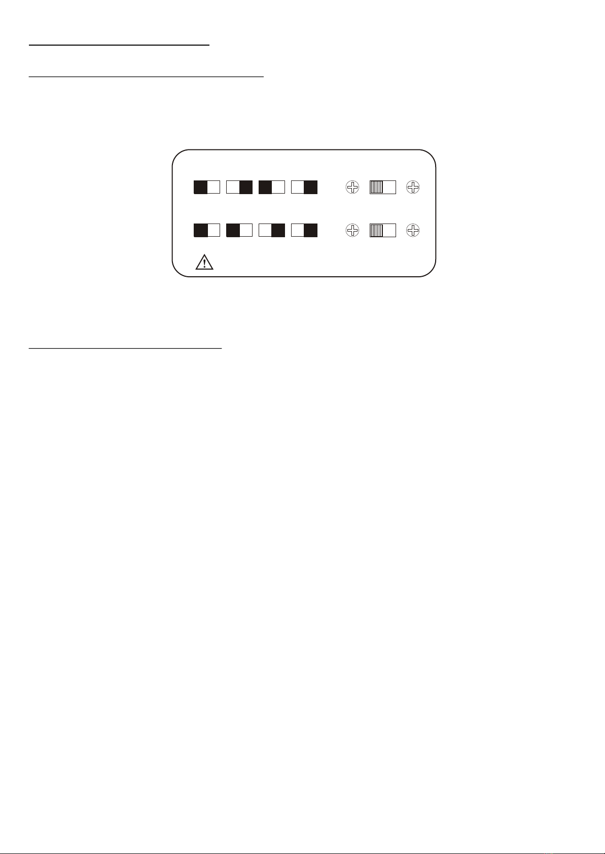
110V120V230V240V
INPUT VOLTAGE SELECTION TABLE
Warning : SELECT EXACT COMBINATION OF BOTH UPPER &
LOWER SELECTORS FOR CORRECT LINE VOLTAGE
SETTING BEFORE AC PLUG IN.
7. Operation Procedure
7.1. Correct Input Voltage Selection
It is important to select the exact input voltage setting as close to the mains supply as possible for
safety and rated line voltage regulation. Correct setting requires exact combination of both the Upper and
Lower switches as shown below.
The same information is also given on the back panel of the unit.
7.2. Normal Operation Mode
In this operation mode, the three outputs (Master, Slave and the Auxiliary) are totally Independent of
each other and fully isolated. They operate as 3 separate power supplies. The Master and Slave are designed
to operate as constant voltage source or as a constant current source. This power supply is designed to
operate as a constant voltage source or as a constant current source.
Automatic crossover to either mode of operation occurs when load conditions change as following:
CONSTANT VOLTAGE
The power supply will function as a constant voltage source as long as the load current is less than the
current limiting value set by the current limit operation. When the load current is equal to or greater than the
current limit set, the power supply will automatically cross over and operate as a constant current source.
CONSTANT CURRENT (AUTOMATIC CROSS OVER)
The power supply will function as a constant current source when the load voltage does not equal to the
voltage value set by the output voltage control. When the load voltage equals to the value set by the output
voltage control, the power supply will automatically cross over and operate as a constant voltage source.
PRESETTING CURRENT LIMITING VALUE
There are occasions that you do not want your load to draw too much current and from being damaged,
you can preset the current limiting value as following.
Short circuits the output terminals and adjust the current limit control to your desired value.
PRECAUTIONS
1. Do not cross-connect output terminals in normal mode.
Only use outputs 21 & 22 for Slave, 23 & 24 for Master.
2. Always double check for correct output connections before using the Mode Switch.
110V120V230V240V
INPUT VOLTAGE SELECTION TABLE
SELECT EXACT COMBINATION OF BOTH UPPER &
LOWER SELECTORS FOR CORRECT LINE VOLTAGE
SETTING BEFORE AC PLUG IN.
Warning :
P.5

7.3. Series Mode Operation ( Tracking )
When the mode selector is set at series mode, the Master and Slave power supplies are in effect joined
in series so that double voltage capacity becomes available from terminal 21 and 24 only.
Before switching to the series mode, it is important to set the current control of Slave to maximum level
make sure there is no other load on all other output terminals.
Connect load only to terminal (21) and (24)
The overall current and voltage adjustment are controlled at the Master side (14,15) and so are the CC
and CV indicators.
Current level is read from the Master's ammeter.
Voltage level is the sum of the Slave's and Master's voltmeters.
7.4. Parallel Mode Operation ( Tracking )
When the mode selector is set at parallel mode, the Master and Slave power supplies are in effect joined
in parallel so that double current capacity is from output terminals 22 & 23.
Before switching to the parallel mode, it is important to set the current control of Slave to maximum
level make sure to connect only one load to the desired output terminals.
The overall current and voltage adjustment are controlled at the Master side and so are the CC and CV
indicators. The CC indicator at the Slave side is always on.
Voltage level is read from the Master's voltmeter.
Current level is the sum of the Slave's and Master's ammeters.
7.5. Auxiliary Power Output ( Logic Output )
This third independent power output has 1.5 to 6 VDC and 5 A capacity.
Output voltage and current levels can be read from the voltage and current meters at the Master side by the
following procedures.
A. One quick push on the Aux. Button will switch the Master's voltage & current meters to
display the Auxiliary Power Output for about 10 seconds.
B. Two quick pushes on the Aux Button will display the Auxiliary Power Output until the third
quick push to return to normal Master output.
C. The green LED at the left side of the Aux Button will light up when meters are displaying
readings of the Auxiliary Power Output.
D. When the loading current exceeds 5A, the red LED at the right side of the Aux Button will light up.
P.6
This manual suits for next models
3
Table of contents
Popular Laboratory Equipment manuals by other brands


Grant-bio
Grant-bio PS-3D operating instructions

Neuation
Neuation iFUGE M24PR Product user manual

View
View Benchmark 450 Service manual

STEMCELL
STEMCELL ThawSTAR CFT2 quick start guide

Baker Ruskinn
Baker Ruskinn Sci-tive SI-046 Service Procedure

10x Genomics
10x Genomics Chromium Single Cell Controller Readiness... manual

ThermoFisher Scientific
ThermoFisher Scientific Thermo Scientific IMP 180 operating instructions

Rocker
Rocker CR 25 instruction manual

Hardy Diagnostics
Hardy Diagnostics QuickSlide HemaPRO User's operation manual

Sartorius Stedim Biotech
Sartorius Stedim Biotech BIOSTAT CultiBag RM 600 operating manual

Argos
Argos ThinSpin Operator's manual

horiba
horiba 7544 instruction manual