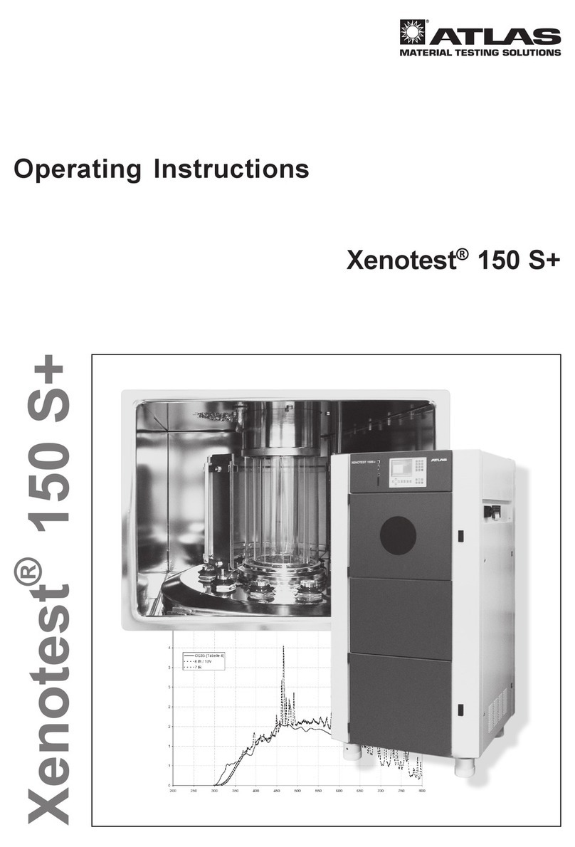
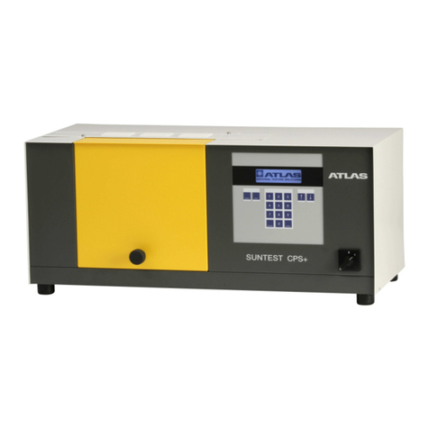
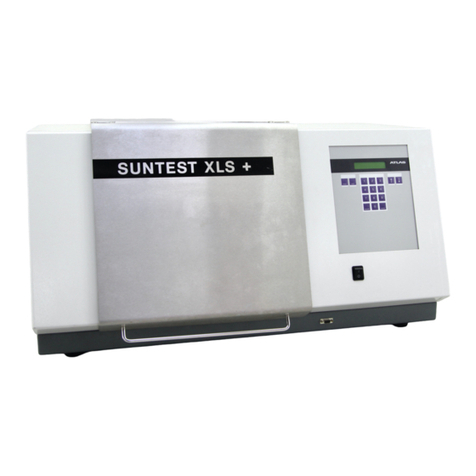
Atlas SUNTEST CPS+ User manual

Operating Manual
300 400 500 600 700 800
0
1
2
3
4
5
6
7
8
trale Bestrahlungsstärke /W/m2/nm
Wellenlänge [nm]
Daylight reduced IR
CIE 85 Tabelle 4
SUNTEST CPS+
SUNTEST CPS+
®
Spectral Irradiance
Wavelength [nm]
SUNTEST®CPS+

- 2 -
Operating Manual SUNTEST®CPS+
Content
1 Notes for safe operation.................................................................................................................................4
1.1 Explanation of the symbols..........................................................................................................................6
1.2 General instructions for safe operation........................................................................................................7
2 Installation of the instrument.......................................................................................................................10
2.1 Scope of delivery........................................................................................................................................10
2.2 Packing ......................................................................................................................................................10
2.3 Installation requirements............................................................................................................................ 11
2.4 Installation.................................................................................................................................................. 11
3 Description of the instrument......................................................................................................................12
3.1 Front view...................................................................................................................................................12
3.3 Rear view...................................................................................................................................................12
3.3 Test chamber..............................................................................................................................................13
4 Description of functions...............................................................................................................................14
4.1 Radiation and lters ..................................................................................................................................14
4.2 Ventilation circuits ......................................................................................................................................14
4.3 Filter systems.............................................................................................................................................15
4.4 Spectral distribution ...................................................................................................................................16
4.5 Sensor system ..........................................................................................................................................17
4.6 Safety facilities...........................................................................................................................................18
4.7 Safety labels...............................................................................................................................................18
5 Installation .....................................................................................................................................................19
5.1 Mounting of black standard sensor............................................................................................................19
5.2 Assembling the radiation system ...............................................................................................................19
5.2.1 Components of the radiation system.....................................................................................................19
5.2.2 Opening of the assembly compartment ...............................................................................................20
5.2.3 Installation of the optical lters..............................................................................................................20
5.2.5 Installation of the mirrors.......................................................................................................................21
5.2.6 Closing the assembly compartment......................................................................................................22
5.3 Connection to the power supply.................................................................................................................22
6 Operation and shutdown..............................................................................................................................23
6.1 Conguration of the instrument ..................................................................................................................23
6.2 Standard testing procedure........................................................................................................................23
6.3 Testing procedure with optional unit...........................................................................................................23
6.4 Operation with program controller..............................................................................................................24
6.5 Shutdown...................................................................................................................................................25
6.6 Final shutdown...........................................................................................................................................25
7 Calibration......................................................................................................................................................26
7.1 Irradiance...................................................................................................................................................26
7.2 Black standard temperature.......................................................................................................................27
8 Cleaning / consumables...............................................................................................................................28
8.1 Cleaning ....................................................................................................................................................28
8.1.1 Outer surfaces and operating elements................................................................................................28
8.1.2 Reector................................................................................................................................................28
8.1.3 SUNSENSIV™-sensor..........................................................................................................................28
8.1.4 Radiation system...................................................................................................................................28
8.1.5 Air lter..................................................................................................................................................28
8.2 Consumables / spare parts........................................................................................................................29
9 Maintenance...................................................................................................................................................30
9.1 Maintenance ..............................................................................................................................................30
9.2 Spare parts.................................................................................................................................................30
10 Technical Data...............................................................................................................................................31
11 Accessories...................................................................................................................................................32
12 Declaration of conformity.............................................................................................................................34
13 Notes ..............................................................................................................................................................37
Page

- 3 -
Operating Manual SUNTEST®CPS+
List of Graphics and tables Page
Fig. 1 Description of the SUNTEST®CPS+, front view........................................................................................12
Fig. 2 Description of the SUNTEST®CPS+, rear view.........................................................................................13
Fig. 3 Test chamber..............................................................................................................................................13
Fig. 4 Radiation and lters ...................................................................................................................................14
Fig. 5 Ventilation circuits ......................................................................................................................................14
Fig. 6 Spectral distribution....................................................................................................................................16
Fig. 7 Sensor system ...........................................................................................................................................17
Fig. 8 Safety facilities...........................................................................................................................................18
Fig. 9 Safety labels...............................................................................................................................................18
Fig. 10 Mounting the black standard sensor..........................................................................................................19
Fig. 11 Components of the radiation system..........................................................................................................19
Fig. 12 Opening of the assembly compartment ....................................................................................................20
Fig. 13 Installation of the optical lters ...................................................................................................................20
Fig. 14 Installing the xenon lamp ...........................................................................................................................21
Fig. 15 Installation of the mirrors............................................................................................................................21
Fig. 16 Closing the assembly compartment...........................................................................................................22
Fig. 17 Connection to the power supply.................................................................................................................22
Fig. 18 Standard testing procedure........................................................................................................................23
Fig. 19 Operation with program controller..............................................................................................................24
Fig. 20 Data transfer to a PC .................................................................................................................................26
Fig. 21 Calibration of irradiance with the XenoCal®WB 300 - 800 Sensor............................................................27
Fig. 22 Calibration of black standard temperature with XenoCal®BST Sensor or SunCal®sensor (optional).......27
Tab. 1 ...................................................................................................................................................................24

- 4 -
Operating Manual SUNTEST®CPS+
Instructions for the user:
This operating manual describes the SUNTEST CPS+ xenon arc instrument. Please note that the instrument should
only be operated by authorized and qualied personnel.
Qualied personnel are users who:
• Have gained knowledge of instrument operation through an Atlas authorized technical training
• Have been instructed in the operation and function of the Instrument on the basis of this operating manual
• Are able to assess the activity that they perform based on work experience and instruction in the relevant safety
conditions and recognize possible hazards
Maintenance work:
• The lamp in the lamp cassette may only be replaced by qualied personnel who have been instructed by an
electrician or authorized Atlas representative
Cleaning work:
• Cleaning of the instrument or parts may only be performed by trained personnel
Read this operating manual carefully before using the Instrument for the rst time. You will then be able to
utilize all of the instrument features and avoid damage.
Should a particular problem arise which you feel is not adequately addressed in these operating instructions,
we urge you for your own safety to contact your local Atlas ales or Service Representative.
1 Notes for safe operation
Atlas Material Testing Technology GmbH
Vogelsbergstr. 22
63589 Linsengericht / Germany
Phone: +49 (0)6051 707-140
Fax: +49 (0)6051 707-149
E-mail: [email protected]
www.atlas-mts.com

- 5 -
Operating Manual SUNTEST®CPS+
1 Notes for safe operation
Instructions for the user:
The SUNTEST CPS+ has been constructed with state-of-the-art technology and business practices and is safe to
operate. However, this instrument could be hazardous if operated by untrained personnel or utilized in a manner for
which it was not intended.
Instruction and prevention of accidents:
• For personnel who work on and with this instrument, the owner must create written instructions in a comprehensive
form and in the language of the employees based on this operating manual (FRG: Directive for the Prevention
of Accidents, UVV BGVA1)
• The work health and safety regulations of the trade cooperative associations BGV A3 must be observed
• Instruct the operating and cleaning personnel in the operation and care of the instrument based on these
instructions
• Unauthorized modications or conversions to the instrument are not permitted for safety reasons
Warranty:
Atlas MTT GmbH guarantees the safety and functional capability of the instrument only on condition that:
• Only original spare parts or accessories approved by Atlas MTT are used
• Inspections, calibrations and maintenance work are performed according to the given time intervals
Validity of the contents of the manual:
• The contents of these operating manual are subject to change at any time without notice
• The German version of this operating manual is binding for translations into foreign languages
Keep this operating manual in a safe place near to the instrument to be able to consult safety instructions
and important operating information at all times.
Copyright©
Atlas Material Testing Technology GmbH • 63589 Linsengericht / Altenhaßlau • Germany

- 6 -
Operating Manual SUNTEST®CPS+
Safety symbols will draw your attention to safety-critical operation errors.
Symbols used in this operating manual
WARNING: Indicates a hazardous situation which, if not avoided,
could result serious injury or death
CAUTION: Indicates a hazardous situation which, if not avoided,
could result in minor or moderate injury
NOTE: Provides usage tips and useful information
WARNING from dangerous electrical voltage:
Indicates an electrical hazard
WARNING of UV radiation
CAUTION: wear UV safety glasses
CAUTION of cuts and gashes
WARNING against toxic substances
Symbols on the instrument
REFERENCE TO DISPOSAL DIRECTIVE (WEEE)!
The disposal of this product must comply with the EC Directive 2012/19/
EU (updated version) concerning used electrical and electronic
instruments.
CE Conformity mark
Pull main power supply
plug before opening ! Warns you not to touch live parts of the instrument
when opening.
1 Notes for safe operation
1.1 Explanation of the symbols

- 7 -
Operating Manual SUNTEST®CPS+
1 Notes for safe operation
1.2 General instructions for safe operation
Please follow the safety instructions in the individual chapters.
Usage as authorized:
• The SUNTEST®CPS+ is used for exposure and weathering of material samples.
• The instrument is suitable for continuous operation.
• The instrument has been tested for electromagnetic compatibility and for installation in an industrial application.
Unauthorized usage:
• Flammable or explosive substances should not be exposed in the test chamber (see Ordinance on Hazardous
Substances).
• No substances or materials that may release toxic substances in any form should be used in the test chamber.
• Atlas does not guarantee performance of the Instrument instrument for test cycles that utilize light/dark cycles
less than 30 minutes in length. Thereof unaffected is the programming of smaller times insofar they do not repeat
cyclic.

- 8 -
Operating Manual SUNTEST®CPS+
1 Notes for safe operation
1.2 General instructions for safe operation
Please also follow the safety instructions in the individual chapters.
Safety instructions for installation:
WARNING – Pull out the power plug
Coming in contact with live parts can result in a possibly fatal electrical shock. When assembling
the irradiance system, set the ON (I) / OFF (O) switch to the “OFF (O)” position and pull out the
power plug. Secure the power plug from being inserted again.
WARNING – UV radiation
If the sample table is not used, UV radiation is emitted on the lower side of the instrument and can
result in damage to skin and retina. Always use the sample table when the instrument is running!
WARNING – Short wavelength (UV-B) radiation
If the mirrors (gure 14) are not used, UV radiation is emitted on the upper side of the instrument and can
result in damage to skin and retina. Always operate the instrument with the mirrors installed.
Do not run the instrument without installed lter system.
The minimum lter conguration is the basic lter:
• Special UV
• Optical “Coated Quartz” lter
CAUTION – Danger of cuts and gashes
The optical lters have sharp edges that may cause cuts and gashes.
Always wear protective gloves when working on the radiation system.

- 9 -
Operating Manual SUNTEST®CPS+
1 Notes for safe operation
1.2 General instructions for safe operation
Please also follow the safety instructions in the individual chapters.
The instrument meets the following safety regulations:
• DIN EN ISO 12100 Parts 1 and 2, 2004-04
Safety of machinery.
• DIN EN 50178 (VDE 0160): 1998-04
Electronic equipment for use in power installations.
• DIN EN 61000 Part 6-2, 2006-03 (VDE 0839)
Electromagnetic compatibility, Professional Basic Norm, immunity from distortion. Part 1: Residential areas, busi-
ness and industrial areas as well as small industries. Part 2: Industrial area.
• DIN EN 61010 Part 1, 2002-08 (VDE 0411)
Safety regulation for electrical measurement, control and laboratory instruments.
Disposal:
OBSERVE DISPOSAL DIRECTIVE!
Since March 24, 2006, the manufacturers` obligation to take back used instruments in accordance
with the EC Directive 2012/19 EU (updated version) WEEE (Waste Electrical and Electronic Equipment)
apply within the respective national implementation.
Compliance with RohS:
The SUNTEST®CPS+ complies with the requirements of directive 2011/65/EU for restricting the use of certain dan-
gerous substances in electrical and electronic instruments. This directive does not apply to instruments which are
designed exclusively for the purposes of research and development and are only provided at intra-company level.
Therefore, the SUNTEST CPS+ instrument does not come under the validity of the above mentioned directive.
Disposal of packaging:
Please discard the packaging materials according to the applicable regulations. For a list of the used packaging
materials, please refer to Section 2.2, “Packaging Materials.”

- 10 -
Operating Manual SUNTEST®CPS+
2 Installation of the instrument
2.1 Scope of delivery
The SUNTEST CPS+ consists of:
• Xenon lamp
• Optical lter “Coated Quartz Filter Segment”
• UV mirror and light mirror
• Sample table
• Sensor for measuring and controlling irradiance (E)
• Sensor for measuring and controlling the black stan-
dard temperature (BST)
• Sensor for measuring the chamber temperature
(CHT)
• Program controller with a screen for displaying data
and keyboard for data input
• ON (I) / OFF (O) switch
• Serial RS232 port for connection to a PC.
• Operating and software documentation manuals
2.2 Packaging
• Polyethylene foam (PE)
• Corrugated cardboard

- 11 -
Operating Manual SUNTEST®CPS+
2.3 Installation requirements
Climatic conditions required for the place of instal-
lation:
• During continuous operation, the hot air emitted by the
air-coolingsystem resultsin aconstantlychanging cli-
mateinthe room.Therefore,the SUNTESTinstrument
should only be installed in air-conditioned, sufciently
ventilated areas.
• The room temperature must be maintained between
18° C and 25° C.
• The maximum relative humidity should be 50%
(+/- 10%).
The requirement for cooled air is as follows:
• 150 m³/h each for lamp cooling and cooling of the test
chamber.
2 Installation of the instrument
2.4 Installation of the instrument
Installation of thr SUNTEST CPS+:
• Dimensions of the instrument (width x depth x height):
780 mm x 350 mm x 350 mm,
• Weight of the instrument: approx. 30 kg,
• Stand the instrument on a sufciently stable, horizontal
laboratory bench.
Caution – overheating of the instrument
The instrument will overheat and be damaged
if the air inlet and outlet are obstructed!
Keep the following minimum distances away
from adjacent walls or objects for installation.
• Keep the top of the instrument free; do not place objects
on the instrument.
• At the back of the instrument 30 cm.
• At the left and right hand sides of the instrument 10 cm.
• Mutual inuences of the supply and exhaust air must
be prevented when installing several instruments.
NOTE – Transport
The instrument may only be transported by experienced
service personnel with suitable equipment.

- 12 -
Operating Manual SUNTEST®CPS+
RS232 Interface
Port for connecting the optional cooling/immersion
instrument
Air inlet opening for lamp cooling and temperature
regulation of the test chamber
Power plug with connecting cable
Air outlet for lamp cooling and temperature
control of the test chamber
3.3 Rear view
Rear side of the instrument:
• RS232 interface for data transfer to a PC
• Port for connecting the optional cooling instrument
or immersion unit
• Air inlet opening for the xenon lamp cooling and
the temperature control of the test chamber
• Power plug with connecting cable
•Air outlet for lamp cooling and the temperature
control of the test chamber
3 Description of the instrument
Covering hood
Program controller
Display
Numeric keyboard
ON (I) / OFF (O) switch
Test chamber door
Air outlet of the lamp cooling and temperature
control of the test chamber
3.1 Front view
TheSUNTESTCPS+isequippedwithamicroprocessor-
based control for measurement and regulation; the unit
has software-controlled testing programs.
Top:
• Covering hood of the assembly compartment for
the lamp and ltering systems
Front:
• Program controller with
• Display
• Numeric keypad
• ON () / OFF () switch
• Test chamber door
Left side:
• Air outlet for lamp cooling and temperature control
of the test chamber
0
1
2
3
4
5
6
7
12345
Fig. 1
Fig. 2

- 13 -
Operating Manual SUNTEST®CPS+
3 Description of the instrument
Door lock switch
Test chamber door
Reector
Sensor for measuring irradiance
Air inlet for temperature regulation in the test
chamber
Black standard sensor (BST)
Sample table
3.3 Test chamber
• Door lock switch for opening / closing the test
chamber door
• The reector is located in the test chamber and in
the test chamber door. The xenon lamp is located in
the roof of the test chamber
• The sensor to measure the irradiance (E)
• Black standard sensor (BST) to measure the black
standard temperature at sample level
• Air inlet for temperature control in the test chamber
• Sample table used for positioning the samples
0
1
2
3
4
5
6
7
Fig. 3

- 14 -
Operating Manual SUNTEST®CPS+
• The samples are placed on the sample table .
Radiation is generated with a xenon lamp and
ltered through an optical “Coated Quartz” lter
NOTE – Optional optical lters
There are optional optical lters (see Chapter 11 “Acces-
sories”) available for various spectral distributions (see
chapter 4.3, “Spectral distribution with additional lters”)
• The UV component of the radiation that is directed
upwards is reected on the samples by the mirrors
placed above the xenon lamp
• The components of the non-dangerous IR radiation
(heat radiation) might penetrate through the mirrors.
The remaining heat is removed out of the unit via the
air circuit of the xenon lamp
4 Description of functions
Cooled air supply for the xenon lamp and control
of the chamber temperature (CHT)
Cooled air outlet of the xenon lamp and control
of the chamber temperature (CHT)
4.1 Radiation and lters
4.2 Ventilation circuits
The cooling air of the xenon lamp ows from the rear
side of the instrument through an air lter. Air then ows
through the test chamber and the assembly compart-
ment of the irradiance unit and exits through the exhaust
openings (at the left and the rear side of the unit (see
chapter 3.2, “Rear view”).
NOTE – Changing of the ambient room
temperature
During continuous operation, the hot air emitted by the
air cooling system will effect ambient room temperature.
Mirrors (UV and light mirrors)
Optical “Coated Quartz” lter
Xenon lamp
Radiation
Sample table
Samples
0
I
1
2
IR-radiation
(inrared radiation)
3
6
5
4
2
1
UV-radiation and
visible light
Fig. 4
Fig. 5

- 15 -
Operating Manual SUNTEST®CPS+
4 Description of functions
4.3 Filter systems
Description Consisting of: Simulation of:
Max UV
reduced IR Coated quartz glass “UV max”; extreme,
unnatural UV exposure *
Daylight
reduced IR Coated quartz glass
+ UV special glass Solar radiation outdoors
Window glass
reduced IR Coated quartz glass
+ special window glass Exposure behind 3 mm window glass
ID 65
reduced IR
Coated quartz glass
+ special window glass
+ Solar ID65
Solar radiation behind 6 mm window
glass, according to ICH Guideline *
Solar Standard
reduced IR Coated quartz glass
+ Solar Standard Solar radiation outdoors according to DIN 67501
StoreLight
reduced IR Coated quartz glass
+ Store light lter Articial indoor light *
* only for 300 - 800 nm

- 16 -
Operating Manual SUNTEST®CPS+
4 Description of functions
4.4 Spectral distribution
300 400 500 600 700 800
0
1
2
3
4
5
6
7
8
W/m
2
/nm
Wavelength [nm]
Daylight reduced IR
CIE 85 Tabelle 4
250 300 350 400
0,0
0,5
1,0
1,5
2,0
Wavelength [nm]
maxUV reduced IR
Daylight reduced IR
Window Glass reduced IR
Spectral Irradiance
W/m
2
/nm
Spectral Irradiance
Fig. 6

- 17 -
Operating Manual SUNTEST®CPS+
4 Description of functions
4.5 Sensor system
The SUNTEST CPS+ has integrated sensors for
measuring:
Irradiance (E):
• During testing, irradiance is measured by a sensor
and regulated electronically
• The calculation of the irradiance (H) in the wavelength
range 300 nm – 800 nm or
• The calculation of the irradiance (H) in the wavelength
range 300 nm – 400 nm
• Irradiance level controlled and displayed is calculated
at the sample plane
Black Standard Temperature (BST):
• During testing, the black standard temperature sensor
continuously measures the temperature
• The black standard temperature is regulated via the
speed of the test chamber fan
Test chamber temperature (CHT):
• Measurement of the test chamber temperature actual
values. The values can be seen on the controller dis-
play
Measured data:
• The measured data can be transferred via the RS232
port at the rear side of the instrument to a PC with a
serial interface while the test program is running
1Sensor for measuring the irradiance
2Black standard temperature sensor (BST)
0
1
2
Fig. 7

- 18 -
Operating Manual SUNTEST®CPS+
ON (I) / OFF (O) switch
Door switch for test chamber door
Safety switch for lamp replacement
Temperature safety instrument
4 Description of functions
4.6 Safety facilities
There are safety and protection instruments that
increase the operational and functional safety of the
instrument:
• To switch off the instrument in an emergency, set the
ON (I) / OFF (O) switch to position “OFF (O)”
• A door switch shuts off the instrument when the test
chamber door is opened
• A safety switch interrupts the power supply when the
covering hood of the assembly compartment is
removed
• A temperature safety instrument shuts off the unit if
there is a danger of the xenon lamp getting overheated
because of insufcient cooling
4.7 Safety labels
Please check whether the safety labels mentioned
below have been put on the instrument. If any of the
safety labels are missing, please inform your supplier.
• The safety label
• This label “Pull out main power supply plug before
opening the instrument!” on the rear side of the instru-
mentwarnsyounot to touchlivepartsof the instrument
when you open it
Pull out main power supply plug
0
1
3
4
2
1
Pull out main power sup-
ply plug before opening
the instrument!
Fig. 8
Fig. 9

- 19 -
Operating Manual SUNTEST®CPS+
5 Installation
5.1 Mounting of black standard sensor
1. Place the black standard sensor on the sample
table .
NOTE
In order to receive reproducible and comparable tests,
always place the black standard sensor in the same place
on the sample table.
NOTE
The installed sample table is important to avoid damaging
UV radiation.
5.2 Assembling the radiation system
The sample table and the radiation system need to be
assembled before the instrument can be operated.
5.2.1 Components of the radiation system
The radiation system is packed separately. Please check
the components for damage before assembly. Damaged
parts must not be installed.
The radiation system consists of:
The optical “Coated Quartz” lter
The additional optional optical lter
(see chapter 11, “Accessories”)
The xenon lamp
The UV mirror (transparent), pre-mounted
The light mirror (mirror coating)
NOTE
When assembling the optical lter, put the coated (or
optional uncoated) quartz filter and then the selected
optional additional lter in place.
Handle
Test chamber door
Black standard sensor
Sample table
Optical “Coated Quartz” lter
Optional/additional optical lter
Xenon lamp
UV mirror (transparent)
Light reector (mirror coating)
CAUTION – Danger of burns
To cool the radiation system, the fan
continues to run even after the instrument
has been switched off. Open the test chamber
only after the fan has automatically been
switched off.
1
2
3
4
5
0
1
2
3
4
Fig. 10
Fig. 11

- 20 -
Operating Manual SUNTEST®CPS+
0
1
2
3
Recessed head screws (2x)
Covering hood of the radiation system
Assembly compartment
5 Installation
5.2.2 Opening of the assembly compartment
WARNING – Pull out the power plug
Coming in contact with live parts can result
in a possibly fatal electrical shock.
When installing the radiation system, set
the ON (I) / OFF (O) switch to the “OFF (O)”
position and disconnect the power plug.
Secure the power plug to avoid reconnection.
1. SettheON (I)/OFF (O) switch tothe OFF (O)position.
Pull the plug out of the socket. Secure it against being
inserted again.
2. Loosenthetwo recessedhead screws withascrew-
driver.
3. Remove the covering hood of the radiation system
upwards and set it aside.
4. The assembly compartment is now freely acces-
sible.
Coated quartz lter („Max UV reduced IR“)
Holding frame in the assembly compartment
Optional additional lter
5.2.3 Installation of the optical lters
Clean the optical lters before assembling with a soft
cloth. Carefully wipe the optional “UV special glass” lter
with a lint-free cloth moistened with a pure, mild solvent,
e.g. isopropyl alcohol.
CAUTION – Danger of cuts and gashes
The optical filters have sharp edges that
may cause cuts and gashes. Always wear
protective gloves when working on the
radiation system.
NOTE – Position of the optical lter
The holding frame in which the optical lters are placed
is located in the assembly compartment.
1. Put on protective gloves
2. First place the optical „Max UV reduced IR“ (coated
quartz lter) inthe holdingframe inthe assembly
compartment
3. Then position the optional optical lters (seechapter
11, “Accessories”)
1
3
2
Fig. 12
Fig. 13
Table of contents
Other Atlas Laboratory Equipment manuals
Popular Laboratory Equipment manuals by other brands

Thermo Scientific
Thermo Scientific Nicolet Summit user guide

JCHADWICK
JCHADWICK 8400K user manual

Thermo Electron
Thermo Electron Spectra-Tech 0045-322 installation guide

socorex
socorex Acura Electro 926 operating instructions

Agilent Technologies
Agilent Technologies OmnoBER 725 quick start guide

Hirschmann
Hirschmann solarus instruction manual