Mantle LS20 User manual
FAMILY RUN BUSINESS
ESTABLISHED IN 1997
Packaging Machinery Ltd
LS20 instruction manual
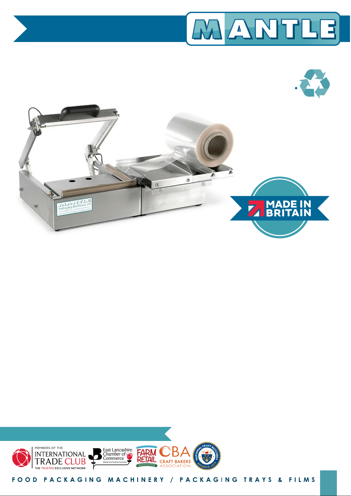
small stainless steel l sealer for use with polypropylene film
Units 1 & 2 The Sidings,
Whalley , Lancashire, BB7 9SE
Tel: 01254 824992
Email: [email protected]
Website: www.mantlepackaging.co.uk
WE ARE PROUD MEMBERS OF
T
H
I
S
M
A
N
U
A
L
I
S
P
R
I
N
T
E
D
O
N
R
E
C
Y
C
L
E
D
P
A
P
E
R
This manual is produced by Mantle Packaging Machinery Ltd for the benefit of machine users and should be carefully studied prior to
installation or operation of the machine, and then kept safely for the training purposes of future operators. Although every effort is made to
ensure that the information in this manual is accurate, due to continuing improvement and development, some of the content may differ in
some way from the machine that you have. On receipt the machine should be thoroughly inspected and any damage should be notified
to the carrier and Mantle Packaging Machinery Ltd immediately.
DESCRIPTION & SPECIFICATION
The machine is robustly constructed from the finest materials available and each unit is guaranteed for 6 months against faulty workmanship.
Following years of experience in Food Packaging Machinery, this machine has been manufactured to meet the need for a simple yet
workmanlike machine.
The centre-folded film is supported on free running rollers at the right hand side of the machine; it then passes over and under the dividing
plate. The dividing plate incorporates a film lift to enable the operator to insert the product with minimum effort.
The sealing area of the machine has been fitted with an adjustable height platform to give the best possible sealing position for the product.
Sealing is achieved by electrical impulse, which is initiated by manually closing the sealing head.
Bench Model: -
Sealing Area - 245mm x 200mm : Sealing Platform Descent - 40mm
Overall Length - 630mm : Overall Width - 400mm : Overall Height - 180mm
Electrical Supply: - Finish: -
Single Phase, Neutral and Earth : 240 volt : 10 amps Brushed Stainless Steel , Brushed Aluminium Sealing Head.
1. HEALTH & SAFETY AT WORK
It is essential that operators are correctly trained and follow the instructions detailed in the relevant Operators Manual.
It is essential that only competent and qualified personnel perform any maintenance or repair work.
All warning labels must be complied with.
The following points should be observed for safe usage: -
Do not operate the machine with any panels open or guards removed. Always replace the covers before switching on mains power
following maintenance or repair work. Hair, bracelets, necklaces, neckties or other personal objects may become tangled with moving parts.
Do not override any safety switches, devices, locks, guards etc., and always allow moving parts to stop before making any adjustments.
Do not allow objects to fall into a machine. Never attempt to retrieve objects from inside the machine until a qualified person confirms that
it is safe to do so.
O
U
R
M
A
C
H
I
N
E
R
Y
R
A
N
G
E
I
S
1

2
8. GENERAL CARE & MAINTENANCE
ISOLATE THE MACHINE FROM THE POWER SUPPLY BEFORE ANY
CLEANING OR MAINTENANCE IS UNDERTAKEN
To replace Sealing Wire
Cross (running across the machine from front to back).
Release the terminal at the front (M5 pozidrive). Release end of wire
from spring loaded plunger (M3 socket head screw). Secure terminal
end of sealing wire under M5 screw (pozidrive). Fit plain end of wire
into spring loaded plunger, fully compress the spring and secure with
M3 screw plunger. Remove excess sealing wire remaining at the end
of the plunger.
Front (running across the machine from right to left).
Release old wire in the same manner as the cross sealing wire. When
refitting new wire, observe that the front wire goes into a groove
behind and under the cross sealing wire at the junction of the ‘L’.
ON NO ACCOUNT SHOULD THE WIRE BE CLEANED WITH EMERY CLOTH OR
SAND PAPER, DAMAGE TO THE THERMAL/ELECTRICAL INSULATION OF
THE SEALING HEAD WILL RESULT, REQUIRING COSTLY SHUTDOWN FOR
REPAIR.
Sealing Base
The sealing base consists of a heat resisting sponge rubber, mounted
on an aluminium bar, and covered with a self-adhesive P.T.F.E. tape in
the zone of contact with the sealing wire. Should the top protection
strip (10mm wide P.T.F.E. tape) become badly burnt after continual
use, replace the old strip with new to avoid damage to the sponge
rubber.
Seal Initiating Limit Switch
Situated at the front of the machine. This switch is activated by the
action of the sealing head closing and pressing the switch. The switch
is mounted centrally, and may be set in position by slackening the
locking nuts and moving the switch up and down.
Note! The switch should energize the sealing circuit after the sealing
head has closed
9. CHANGING A SEALING WIRE
10. WARRANTY
Except as in hereinafter expressly stated, Mantle Packaging Machinery
Ltd does not warrant the goods covered by this agreement in any way
and no warranty, expressed or implied is given by the seller, except as
hereinafter set forth.
The machine is warranted against faulty workmanship and flaws in
material. The company will replace any parts, which shall within 6
months from despatch, be proven defective in these respects when
despatched.
The company’s liability is limited to such replacement and it shall not
be held responsible for any direct or consequential damage to
property or person.
The company will not be responsible for any claims or repairs under this
warranty unless such work is authorized by the company.
The company does not guarantee its products for any particular use,
the responsibility for which will rest with the user.
Since there is such a wide variety of conditions under which the
company’s products may operate, including an equally wide variety
of products to be wrapped, no responsibility can be accepted for
damage to the machine resulting from such conditions unless specific
guarantee has been previously given in writing.ditions unless specific
guarantee has been previously given in writing.
secure sealing wire
with locking screw
cut off excess
C-SPRING/54
Tensioner Spring
LS30-015
Sealing Wire Tensioner Plunger
& Locking Screw
C-WIRE/LS20
Sealing Wires (10 Pack)
2. SETTING UP
Bench mounted machines are free-standing on four stick on feet.
Each machine is fitted with 3 metres of 3-core mains cable which
should be connected to a suitable outlet in accordance with existing
regulations. It is essential that a supply of 240 vac, 5 amp is available.
The control panel is located at the front of the machine on the main
frame.
3. OPERATING PROCEDURE
Controls from Left to Right
On/Off Switch Fuse Holder Seal, Time
4. FILM FEED
Centre-folded film of the chosen width and specification is placed on
the rollers at the right hand side of the machine with the open side of
the roll towards the front of the machine.
Note! Centre-folded film may be wound clockwise or anti-clockwise
on its core. The following diagrams show how each of these types of
winding are fed through the machine.
Clockwise Anti-clockwise
rotation at unwind rotation at unwind
After arranging the film in this manner, the film is then parted and split
over and under the dividing plate and draped over the sealing base
of the machine. To prevent film over -running, the FILM BRAKE SCREW
can be adjusted up or down to create pressure on the back roller.
5. SEAL SETTING
Ensure that the mains cable is connected to the electrical supply,
switch machine ON by means of the rectangular switch on the front of
the machine. The neon indicator will light to show the machine has an
electrical supply.
The seal time control can now be set as follows: -
Set SEAL to 3
Run test seal, a buzzer will sound while the sealing wires are being
impulsed. Increase or decrease the SEAL setting until the correct seal
is achieved.
6. OPERATING CYCLE
The machine is now ready to use. Place the product to be wrapped
on top of the dividing plate, and push it under the top layer of film. The
product and film are then moved onto the sealing pack table.
The pack table should be positioned in a suitable slot at approximately
half the depth of the pack.
With the product in this position, lower the sealing head to initiate the
sealing cycle and complete the seal. This should leave the pack
completely enclosed in film. It will be seen that the trailing seal left, is
the seal for the next pack.
7. FAULT FINDING
Fault Mains switch does not illuminate when pressed
Remedy Check there is a mains supply. Check the fuses in the front
panel and mains cable socket.
Fault Mains switch warning light comes on but does not seal.
Remedy Check that the initiating switch is being actuated when the
sealing head closes. Check mains fuse (splatter on fuse backing can
provide sufficient current to illuminate warning light, but not to
operate the machine.
Fault Front sealing wire burns near cross over point of sealing wire.
Remedy Check that cross sealing wire goes under side sealing wire,
and fit a new wire.
LS20 instructions cont.
small stainless steel l sealer for use with polypropylene film
SEAL TIME
FILM BREAK SCREW
FILM BREAK SCREW

C-TAPE-LS-TPS/10
Top Protection Strip
C-TAPE/LS20
Base Cover (Set)*
C-SPONGE/LS20
Base Sponge (Set)*
*C-KIT-LS20 Spares Kit containg:-
2 Base Covers
2 Base Sponge
2 Sealing Wires
C-HANDLE/LS20
Handle
C-ROLLER-LS20
Film Roller
C-GASSPRING/LS20
Gas Spring
C-WIRE-LS20/10
Sealing Wires*
(Pack of 10)
L N N L
E-PCB
Printed
Circuit
Board
E-POTENTIOMETER
Potentiometer
E-FUSEUNIT/5
Fuse Holder
E-SWITCH
On/Off Switch
E-MICROSWITCH-LS20
Micro Switch
240
220
0
34
30
20
0
E-TRANS-LS20
Sealing
Voltage
Transformer
PRIMARY S E C O N D A R Y
C-WIRE-
LS20/10
To Sealing
Wire
LS30-015
To Sealing
Wire Plunger
E-MAINSLEAD
/LS20
Mains Lead
ELECTRICAL SUPPLY:-
Single Phase
Neutral & Earth
240 volt
10 amps
DIMENSIONS:-
630 x 410 x 180mm
MANUFACTURER:-
Mantle Packaging Machinery Ltd
electrical parts diagram
C-INSUL/LS20
Sealing Head Insulation Set
C-FOOT Rubber Stick on Foot
LS20 part diagram
small stainless steel l sealer for use with polypropylene film
DIRECTIVE 2002/96/EC ON WASTE ELECTRICAL AND ELECTRONIC EQUIPMENT (WEEE)
The WEEE Directive aims to reduce the quantity of waste from electrical and electronic equipment and increase it's reuse, recovery
and recycling. Mantle Packaging machines are marked with the "cross out wheeled bin symbol" to ensure they are dealt with
separately from general waste. When the machine has reached the end of it's use, please arrange to have it returned to Mantle
Packaging Machinery Ltd and we will ensure that it is either recycled correctly or disposed of safely. We will record details of all
returned and recycled machines. WEEE Reg No: WEE/DA2698TX 3
Other Mantle Food Saver manuals


