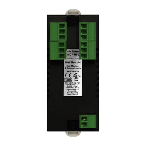
Maple Systems IO-SHSC02 User manual

- 1 -
USER
MANUAL
MAPLE MODULAR PLC
High Speed Counter Module
•
IO-SHSC02

- 2 -
Contents
General Specifications................................. 7
Performance Specifications ......................... 8
Features.....................................................9
Operation Concept ....................................10
Names of Parts..........................................11
Dimensions ..............................................12
Installation ...............................................13
Pin Arrangement.......................................14
Wiring ......................................................16
Wiring Sample ..........................................18
Input Signal Circuit....................................22
Product Warranty ......................................23

- 3 -
Before You Start
This manual contains important information on the use and operation of this device. Please
read all the information carefully for optimal performance and to prevent any damage or
misuse of the device.
To keep products safe, all activities including product installation, wiring operation, and
maintenance are required to be treated by trained personnel.
Reproduction of contents, in whole or part of this manual, without written permission from
MAPLE SYSTEMS Inc. is prohibited.
Safety symbols are classified into two categories, “WARNING” and “CAUTION”.
Warning: This symbol describes situations that could cause major or fatal injury to the
user.
Caution: This symbol describes situations that may cause minor injury or damage to the
device.
SAFETY SYMBOLS USED IN THIS PRODUCT MEAN:
This symbol warns the user of potential hazards.
This symbol warns the user of uninsulated voltage within the unit that can cause
dangerous electric shock.
Keep this manual near the operating devices so it can be easily checked.
If the equipment is used in a manner not specified by the manufacturer, the protection
provided by the equipment may be impaired.

- 4 -
Design Precautions ( Warning)
Please install a safety circuit to protect the entire control system in case of an unexpected
power shutdown or PLC module malfunction. Such anomalies may severely compromise the
integrity of the overall system.
External to the PLC, please install circuits and switches to safeguard the system from
mechanical damages (ex. emergency stop, upper/lower limit switches, forward/reverse
direction interlocking circuits, etc).
When the PLC detects either of the following failure conditions, it may stop operation and
turn off all outputs.
-The overcurrent protection or overvoltage protection of the power supply module is
activated.
-The PLC CPU detected a failure, such as the watchdog timer error or module
installation failure, with its self-diagnostic function.
In addition, all outputs may be turned on when there is a failure that the PLC CPU cannot
detect, such as in the relay or TR terminal. Build an extra monitoring circuit that will monitor
any output signal that could cause serious accidents.
A greater than normal current passed through the PLC for an extended period of time, or a
short-circuited load flowing through the output module may cause a fire.
Build a circuit that turns on the external power supply after the PLC power supply is turned
on. If the external power supply is turned on first, it could result in output failure or
malfunction.
In order to ensure that the system operates safely, please configure an interlock circuit in the
scan program for the following situations.
-When exchanging data with a computer or other devices.
-When operated by a computer or other devices.
Not doing so could result in output failure or malfunction.
Precautions for design ( Caution)
Do not bundle the input/output signal or communication cables with the main circuit and
power cables. They should be installed at least more than 100 mm (3.94 inches) apart. Not
doing so could result in output failure or malfunction.

- 5 -
Precautions for mounting ( Caution)
Use the PLC in an environment that meets the general specifications given in this manual.
Using this PLC in any environment outside the range of the general specifications could
result in electric shock, fire, malfunction, or damage to or deterioration of the product.
Please ensure that each module is installed correctly in its place. Loosely or incorrectly
installed pieces may result in malfunction, failure, or free-fall.
The PLC power supply should be turned off before mounting the module. Not doing so could
cause an electric shock or damage to the device.
Install I/O devices or extension connectors correctly. If they are installed incorrectly, it may
result in an input or output failure.
Do not convey direct vibration into the PLC. Doing so could cause electric shock, fire or
malfunctions.
After wiring work, please make sure to close the terminal cover before turning on the power
for the PLC system.
Precautions for wiring ( Warning)
Make sure to check the device’s rated voltage and circuit arrangement before wiring. Failure
to do so may cause electric shock or damage to the device.
Make sure to close the terminal cover before turning on the power of the PLC system after
wiring work. Failure to do so may cause electric shock.
Precautions for wiring ( Caution)
Make sure to check the device’s regular voltage and sequence of terminals. Failure to do so
may cause fire, electric shock and malfunctions.
Make sure to tighten the screws with standard torque. Loose connections may cause short
circuit, fire, or malfunctions.
In grounding the FG ground terminals, be sure to conduct the product with at least D type
(Class 3) grounding. Not doing so could result in electric shock or malfunctions.
When wiring, make sure that wiring debris does not enter the module. Failure to do so may
cause fire, equipment damage or malfunctions.
The device is only for indoor use.
Use a UL certified product for the power supply. Use a power supply that meets Class 2 or
LVLC (Limited Voltage Limited Circuit) supplied by an isolating source, providing DOUBLE
INSULATION or REINFORCED INSULATION.
This product is an open type equipment and belongs to Overvoltage Category II.
The device is intended to be installed in a suitable fire, mechanical and electrical enclosure.

- 6 -
Precautions for wiring of HSC Module ( Caution)
Cables for the output signals of the HSC module should be separate from AC power to
prevent the influence of surge or induction noise occurring from AC.
Select a cable considering ambient temperature and allowable current.
AWG 22 (0.3 mm2) or more is recommended.
If the wiring is too close to a heat-generating device or directly contacted with oil for long
periods of time it may cause a short circuit, breakdown, or malfunction.
In the case of wiring together with high-voltage cable or power line, a malfunction or
breakdown may occur.
Precautions for test run and repair ( Warning)
Please do not touch the terminals when the power is ON. Doing so could cause an electric
shock or malfunctions.
When cleaning or tightening the screw, turn off the power of the PLC and all other systems.
Failure to do so could cause an electric shock or malfunctions.
Do not charge, disassemble, heat up, short, or solder the battery. Doing so could cause the
battery to heat up, rupture or ignite thereby harming the user.
Precautions for test run and repair ( Caution)
Do not dissociate the PCB from the module’s casing or make any modifications to the
device. Doing so may cause fire, electric shock or malfunction.
When mounting or separating the module, make sure to turn off power to the PLC and all
other devices. Failure to do so could cause an electric shock or malfunctions.
Use radio, walkie-talkie or cellphone devices at least 30cm away from the PLC. Not doing so
could result in malfunction.
Precautions for disposal ( Caution)
When the product is disposed of, it should be done according to your country’s regulations
for similar types of industrial waste. Not doing so may cause an occurrence of toxic
substances or explosions.

General
Specifications
- 7 -
Items Specification Standards
Op. Temp
-
10
℃
–60
℃
-
St. Temp
-
25
℃
–80
℃
-
Op. Hum 5–95% RH, Not condensed
-
St. Hum 5–95% RH, Not condensed
-
Vibration
In case of Intermittent Vibration
IEC 61131-2
Frequency Acceleration Amplitude Sweep
5 ≤f < 9 Hz
-
3.5 mm 10 times
in X, Y, Z
9 ≤f ≤150 Hz 9.8 m/s2(1G)
-
In case of Continuous Vibration
Frequency Acceleration Amplitude Sweep
5 ≤f < 9 Hz
-
1.75 mm 10 times
in X, Y, Z
9 ≤f ≤150 Hz 4.9 m/s2(1G)
-
Shock
Max. shock Acc.: 147 m/s2(15G)
Time: 11 ms
Pulse wave: Half sine wave pulse (3 times in X, Y, Z)
IEC 61131-2
Noise
Square Wave
Impulse Noise
±2
kV
-
Electrostatic
Discharge ±4 kV (Contact), ±8 kV (Air)
IEC 61131-2
IEC 61000-4-2
Radiated
Electromagnetic
Field
80–1000 MHz,10 V/m
IEC 61131-2
IEC 61000-4-3
Fast Transient
Burst Noise
(Voltage)
CPU, Power 2 kV
IEC 61131-2
IEC 61000-4-4
Digital/Analog I/O (AC)
Digital/Analog I/O (DC)
1 kV
Communication
Ambient
Conditions No corrosive gas and no dust
Altitude 2,000 m or less
Pollution Pollution Degree 2 or less
Cooling Natural air cooling

Performance
Specification
- 8 -
Item
Model
IO-SHSC02
I/O Points
16 points
Number of Channels 2 channels
Power consumption 90 mA
Weight 68.5g
Count Input
Signal
Phase 1 Phase input/2 Phase input
Level (фA,фB)
5/12/24 VDC 2—5 mA
Types PNP Encoder (-Common)
Count
Speed 200 kHz
Range
32-bit signed binary values
(-2147483648—2147483647)
Mode Up/Down Preset Counter + Ring Counter
Min. Count Pulse
Period (μS)
(Duty ratio 50%)
Compared
Output
Compared range
32-bit signed binary values
Comparison
Compared value < Present value
Compared value = Present value
Compared value > Present value
External
Input
Preset
5/12/24 VDC 2—5 mA
Enable Count
External
Output Output Compare TR (SINK Type) Output
12—24 V

Features
- 9 -
1.
High Speed Counter (HSC) module covers a wide range of high-speed pulses. (-2147483648—
2147483647) The counted value is stored in the buffer memory as a signed 32-bit binary value.
2.
Different types of operation mode are provided.
-
1 Phase input 1 Multiplication (Increasing/decreasing count operated by software setting),
-
1 Phase input 2 Multiplication (Increasing/decreasing count operated by software setting),
-
CW/CCW
: 2 Phase input 1 Multiplication
: 2 Phase input 2 Multiplication
: 2 Phase input 4 Multiplication
3.
2 counter modes are selectable.
-
Linear counter
Counts within the range of -2147483648—2147483647. If the count exceeds the range, it
overflows.
-
Ring counter
Counts repeatedly between maximum and minimum value.
4.
Output Compare (2 outputs per channel)
This functionality is used to compare present count value with compared value and turn the
Output Compare ON or OFF.
5.
4 types of count functionalities are provided.
-
Latch counter
-
Sampling counter
-
Periodic pulse counter
-
Disable
count
6.
Preset and enable count operation can be run by an external signal.
Input voltage to PRE and FUNC terminal to run preset and enable count operation.

Operation
Concept
- 10 -
1)
Count incoming pulse.
2)
Preset and enable count operation can be operated by the external signal.
3)
Compare the present count value with the compared value and turn Output Compare ON or
OFF. (2 points per channel)
4)
By using scan program, it’s possible to check the I/O signal and buffer memory.

- 11 -
LED
Name Description
PWR Module is powered and initialization is completed.
(PWR LED blinks when an error occurs)
ØA A phase pulse input (V)
ØB B phase pulse input (V)
D
Count is decreasing
P
External preset terminal input (V)
F
Enable count terminal input (V)
O1, O2
Output Compare
Operation/Indicators

Dimensions
- 12 -
(Unit: mm)

Installation
- 13 -

IO-SHSC02 Module Pin Arrangement
- 14 -
Channel Signal Pin No. Channel Signal Pin No.
CH2
A Phase pulse input 24 V A01
CH1
A Phase pulse input 24 V B01
A Phase pulse input 12 V A02 A Phase pulse input 12 V B02
A Phase pulse input 5 V A03 A Phase pulse input 5 V B03
A Phase common ◈A04 A Phase common ◈B04
B Phase pulse input 24 V A05 B Phase pulse input 24 V B05
B Phase pulse input 12 V A06 B Phase pulse input 12 V B06
B Phase pulse input 5 V A07 B Phase pulse input 5 V B07
B Phase common ◈A08 B Phase common ◈B08
Preset input 24V A09 Preset input 24V B09
Preset input 12V A10 Preset input 12V B10
Preset input 5V A11 Preset input 5V B11
Preset input common ◈A12 Preset input common ◈B12
Enable count input 24V A13 Enable count input 24V B13
Enable count input 12V A14 Enable count input 12V B14
Enable count input 5V A15 Enable count input 5V B15
Enable count input common ◈A16 Enable count input common ◈B16
Output Compare 1 A17 Output Compare 1 B17
Output Compare 2 A18 Output Compare 2 B18
External power input for Output Compare 24 V A19, B19
24G A20, B20
◈
NOTE: ( - ) COMMON

IO-SHSC02 Module Wiring
- 15 -
1) IO-SHSC02 Pin Number 2) ACC-TB32M Terminal Block Pin Number
IO
-
SHSC02
Module
ACC
-
TB32M

Wiring
Examples
- 16 -
1.
When waveform generator outputs 5 V. (IO-SHSC02)
2.
When waveform generator outputs 24 V PNP open collector output. (IO-SHSC02)

Wiring
Examples
- 17 -
3.
When waveform generator outputs 24 V NPN open collector output. (IO-SHSC02)
4.
When waveform generator outputs totem pole output (voltage type). (IO-SHSC02)

Wiring
Examples
- 18 -
5.
When waveform generator outputs totem pole output (NPN open collector type). (IO-SHSC02)

Wiring
Examples
- 19 -
7.
Preset, enable count input wiring. (IO-SHSC02)
8.
Output Compare 1, 2 wiring. (IO-SHSC02)

IO-SHSC02 Input Signal Circuit
- 20 -
IO-SHSC02
Table of contents
Other Maple Systems Control Unit manuals
Popular Control Unit manuals by other brands

Fireye
Fireye SB Series manual

nVent RAYCHEM
nVent RAYCHEM Elexant 5010i installation instructions

suprema
suprema OM-120 installation guide

Anritsu
Anritsu Network Master Pro MT1040A Quick reference guide

Task Force Tips
Task Force Tips OASIS HYDRANT ASSIST VALVE INSTRUCTIONS FOR SAFE OPERATION AND MAINTENANCE

Bailey
Bailey Infi 90 IMDSO15 Instruction

ATI Technologies
ATI Technologies PROFINET DL10 manual

Vertiv
Vertiv Geist Replacement guide

Midland
Midland A-14150 Series Installation operation & maintenance

BrickElectric
BrickElectric BEM106 user manual

Pentair
Pentair FLECK 3900 Service manual

Allen-Bradley
Allen-Bradley POINT I/O 1734-ADN installation instructions