Maple Systems RMI5001 User manual

1010-1019 Rev 04 www.maplesystems.com
RMI5001
Installation Guide
Introduction
Thank you for purchasing a Maple Systems RMI5001 non-display HMI
with HDMI port. The RMI5001 is configured using the EZwarePlus
software (purchased separately). This booklet describes the steps
necessary for installing the RMI5001.
For information on programming and configuring the HMI, please refer to
the EZwarePlus Programming Manual (P/N 1010-1015) available on
the EZware software DVD.
For additional information, please refer to the Support Center section of
the Maple Systems website, www.maplesystems.com. The Support
Center provides links to information such as Manuals, FAQs, Technical
Notes, Training Videos, Sample Projects, Controller Information Sheets,
and Controller Cables.

2 RMI5001 Installation Guide
1010-1019 Rev 04 www.maplesystems.com
Static Awareness
Do NOT remove the cover of your RMI5001 product –doing so will void
your warranty. When the cover is removed the circuitry inside is exposed
to possible damage by electrostatic discharge during handling. Minimize
the possibility of electrostatic discharge by:
Discharging personal static by grounding yourself prior to
handling the HMI.
Handling the HMI at a static-free grounded workstation.
Connecting the frame ground ( ) connector of the HMI to a
clean earth ground.
Placing the HMI in an antistatic bag during transport.
Unpacking the Unit
Carefully unpack the HMI. Check all material in the container against the
packing list. Maple Systems will not accept responsibility for shortages
against the packing list unless notified within 30 days. The equipment
and accessories were inspected and tested by Maple Systems before
shipment. Examine the equipment carefully; if any shipping damage is
evident, notify the carrier immediately. Maple Systems is not responsible
for claim negotiations with the carrier. Save the shipping container and
packing material in case the equipment needs to be stored, returned to
Maple Systems, or transported for any reason.
Packing List
RMI5001 Series HMI
Power Connector
RMI5001 Installation Guide
Warranty
A copy of the Warranty and Limitation of Liability is contained in the
product box. It can also be found on our website.

RMI5001 Installation Guide 3
1010-1019 Rev 04 www.maplesystems.com
Technical Support
This manual is designed to provide the necessary information for trouble-
free installation and operation of the HMI. For assistance, please contact
Maple Systems as follows:
Phone: 425-745-3229
Email: support@maplesystems.com
Web: www.maplesystems.com
Installation of HMIs
Information furnished by Maple Systems, Inc., is believed to be accurate
and reliable. However, no responsibility is assumed by Maple Systems
for the use of this information, or for any infringements of patents or other
rights of third parties which may result from its use. No license is granted
by implication, or otherwise, under any patent or patent rights of Maple
Systems, Inc. Maple Systems retains the right to revise or change its
products and documentation at any time without notice.
CE Compliance
The RMI5001 has been tested to conform to European CE requirements,
which meet or exceed the noise emissions and immunity requirements
as set forth in the EN55022 (Emissions) and EN55024 (Immunity)
standards. The products are designed to withstand electrical noise in
harsh industrial environments. They also conform to requirements that
limit electrical emissions. However, this does not guarantee that the
products will be totally immune from possible malfunction in cases where
severe electrical noise occurs.
Therefore, we strongly recommend that you follow the guidelines
outlined in this guide for proper wire routing and grounding to ensure the
proper operation of your unit.

4 RMI5001 Installation Guide
1010-1019 Rev 04 www.maplesystems.com
Environmental Considerations
The RMI5001 is designed to be mounted inside an enclosure rated for
the installation.
The RMI5001 operates in temperatures from -20° to 55°C (-4° to 131°F).
It is intended for indoor installations and may not be suitable for use in
certain outdoor applications. Avoid installing the RMI5001 in
environments with severe mechanical vibration or shocks. Do not install
the HMI in enclosures with rapid temperature variations or high humidity.
Either case will cause condensation of water inside the device and
eventual damage to the HMI.
Warning: Do not operate the HMI in areas subject to explosion
due to flammable gases, vapors, or dusts.
Warning: Conform to UL508 (ISBN 0-7629-0404-6) machine
safety standards for use in Pollution Degree 2 Environments.
Warning: If wiring can potentially be exposed to lightning or
power surges, use appropriate surge suppression devices.
Safety Precautions
Please observe the following precautions when installing the HMI.
Failure to comply with these restrictions could result in loss of life,
serious personal injury, or equipment damage.
Warning: Do not connect the HMI to an AC power source. This
will cause permanent damage to the HMI.
Warning: A Hard-wired EMERGENCY STOP should be fitted in
any system using an HMI to comply with ICS Safety
Recommendations.
Warning: Do not attempt to use a DC power supply that does
not meet HMI power requirements. You may cause malfunction
or permanent damage to the HMI.
Warning: Do not power the HMI with a DC power supply used
for inductive loads or for input circuitry to the programmable logic
controller. Severe voltage spikes caused by these devices may
damage the HMI.
Control Panel Design Guidelines
Pay careful attention to the placement of system components and
associated cable routing. These items can significantly enhance the
performance and integrity of your control application.

RMI5001 Installation Guide 5
1010-1019 Rev 04 www.maplesystems.com
Cable Routing and Noise Immunity
Follow these guidelines when routing cables to the HMI:
Always route the HMI communication cable and the power cable
away from any AC voltage or rapidly switching DC control lines.
Never bundle the HMI cables together with 120VAC power wires
or with relay wiring.
Try to keep at least 8 inches (20 cm) of separation between the
HMI cables and other power wiring. If voltages greater than
120VAC are used in the system, greater separation is required.
If the HMI cables must come near AC wiring, make sure they
cross at 90 degrees.
Run AC power wires in a separate grounded conduit to reduce
electrical noise interference.
Keep the cable lengths for the HMI as short as possible. Do not
coil excess cable and place it next to AC powered equipment.
Cover any equipment used in the enclosure that operates at high
frequency or high current levels with a grounded metal shield.
Power Supply Selection
The power supply used to power the HMI should provide an output of
+24 VDC ±20% measured at the HMI power terminal block. A 24VDC
regulated power supply dedicated to the HMI is recommended. Use a
power supply with adequate current rating based upon your particular
model (visit the Support Center Specifications page on our website).
A power line filter installed at the AC input to the HMI power supply is
highly recommended as a safeguard against conducted RF noise, which
is often present on factory power lines. The wires connecting the output
of the power line filter to the power supply should be kept as short as
possible to minimize any additional noise pickup. The case of the power
line filter should be connected to a quiet earth ground. The power line
filter should have a current rating of at least 3 Amps with common mode
and differential mode attenuation. In applications that may have high
frequency noise present, we also recommend using a resistor (~1 MΩ)
and capacitor (~4700 pF) in parallel to clean earth ground on the DC
output of the power supply.
Do not use the power supply used to provide power to the HMI to power
switching relays, solenoids, or other active devices.

6 RMI5001 Installation Guide
1010-1019 Rev 04 www.maplesystems.com
Figure 1: Typical Panel Layout
PLC/Host
Ground wires
Ground strap
Quiet ground
(isolated)
AC
Power
Line
Filter
RMI
Power
Supply
Shielded
power cable
Control panel is
tied to a reliable
earth ground
2
1
34
5
RMI5001

RMI5001 Installation Guide 7
1010-1019 Rev 04 www.maplesystems.com
Control Panel Grounding
The control panel must be connected to a good, high-integrity earth
ground both for safety considerations and shielding purposes. Maple
Systems cannot overemphasize the importance of good grounding.
Failure to use good grounding procedures during installation may cause
sporadic malfunction of the HMI.
Connect the HMI chassis ground terminal to a reliable earth ground with
a low-resistance path. Refer to Figure 1:
Route all earth ground wires that lead from the HMI, the PLC, the
power supply, and the line filter to a central earth ground point such as a
barrier strip. This will ensure that no ground current from one device
influences the operation of the other devices.
Connect the HMI chassis ground terminal to the control panel using a
heavy-gauge short braided cable (#14 AWG) or ground wire to minimize
resistance. Then, make sure the panel is properly grounded to a clean
earth ground.
Note: If the control panel is made of a non-conductive material, it is
essential that the chassis ground terminal of the HMI is connected to
a clean earth ground point located close to the panel.
Connect the power cable’s shield wire to the HMI’s chassis ground
terminal.
Connect the control panel to earth ground using a copper grounding
rod close to the HMI and control panel.
Hinged doors on control panels do not provide a long-term electrical
connection to the rest of the enclosure. Corrosion develops over time
and prevents good electrical contact. For this reason, a separate wire
braid should be installed from the hinged control panel to the rest of the
enclosure.
For a more in-depth overview of ground wiring techniques, refer to
Technical Note #1027, “OIT Ground Wiring and Electrical Noise Reduction”
in the Technical Notes section of the Maple Systems website.
Installation
It is necessary to follow all installation procedures described in this
chapter for electrical noise immunity and CE compliance. The Maple
Systems HMI is designed to connect easily to your PLC. External
connectors provide quick connections for power, communications and
programming wiring.

8 RMI5001 Installation Guide
1010-1019 Rev 04 www.maplesystems.com
Connect the HMI to Power
Use the 3-position connector supplied with the HMI to provide power to
the HMI. The power cable for the HMI should be 18AWG, 2-conductor
wire with a shield drain wire and protective shield (foil/braid). Cable (P/N
6030-0009) may be purchased by the foot from Maple Systems for
constructing power cables.
Always run the DC ground wire directly back to the signal return of the
power supply. Do not use the chassis ground wire as the signal return.
Caution: To prevent possible damage to the HMI, wait ten
seconds after removing power from the HMI before applying
power again.
To connect the HMI to power:
1. Route the power cable from the HMI to the power supply. The power
cable should not be any longer than necessary.
2. Install the cable wires, referencing the chart below (with colors
shown for Maple Systems Cable 6030-0009):
a. Strip the power cable shield to expose 2” of the black and red
wires.
b. Strip about ¼” of insulation from the black and red wires.
c. Connect the red wire to the positive (+) input of the HMI power
connector and the 24V DC positive (+) output of the power
supply.
d. Connect the black wire to the negative (–) input of the HMI power
connector and the 24V DC negative (–) output of the power
supply.
e. Connect the power cable shield wire to the HMI power connector
FG or ⏚input. Connect the other side to chassis ground.
Wire Color
Power Supply Output
HMI Input
Red
+
+
Black
–
–
Shield
Chassis ground
FG or ⏚
Note: The power connector on the RMI5001 uses a 3-position
terminal block with screw-down clamps. Lugs are not required.
Fusing Requirements
If the HMI does not come on within two seconds of power up, remove
power. An internal solid-state fuse will prevent damage if the polarity of
the DC power is incorrect. Check wiring to ensure proper connections
and try to power up again.
RMI5001 Installation Guide 9
1010-1019 Rev 04 www.maplesystems.com
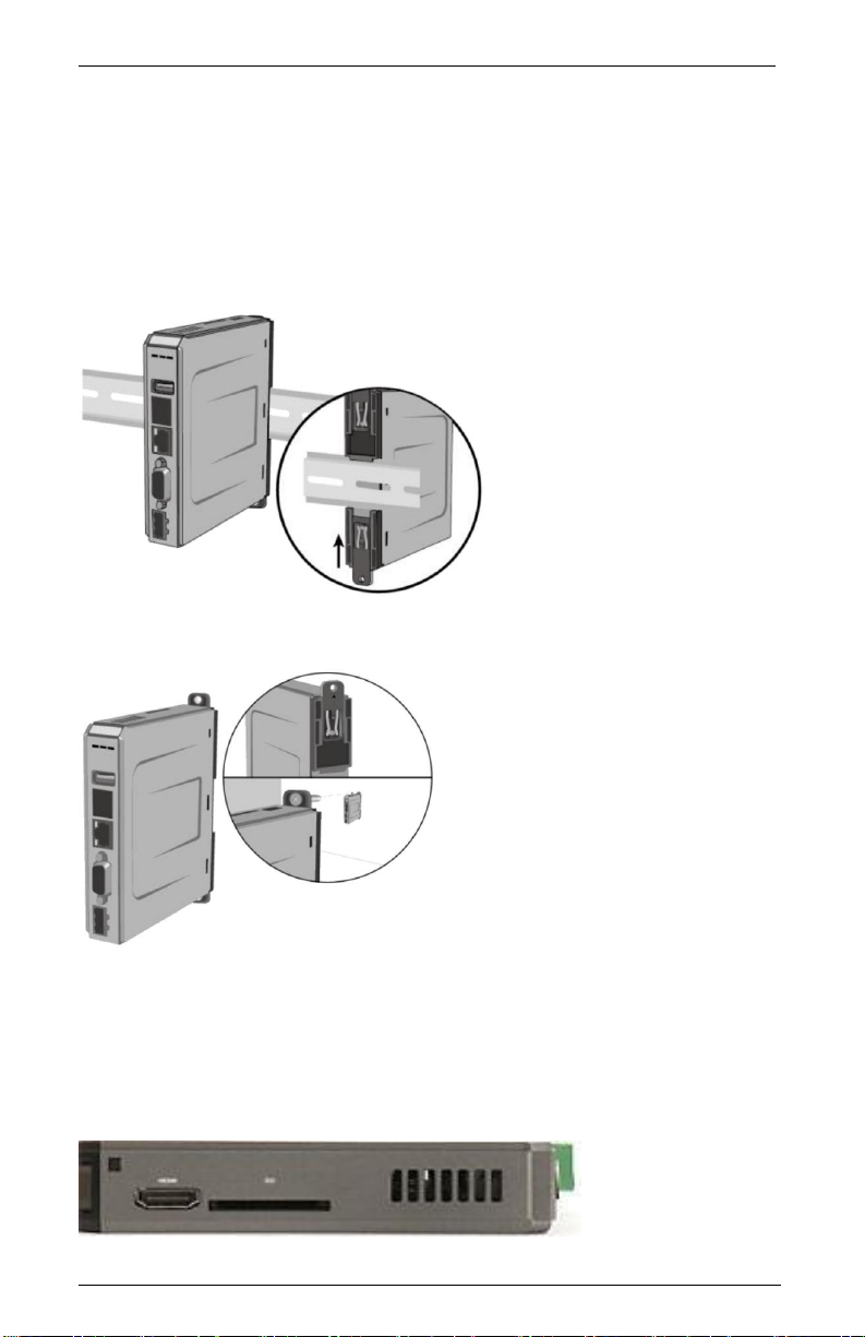
Panel Preparation
The RMI5001 models mount directly on the enclosure’s back or side
panel using 35mm DIN rail, or screwed directly to the panel with user-
supplied M4 or #8 panhead screws.
Mount the HMI to the Panel
Figure 2a: Installing the HMI to DIN rail
Figure 2b: Installing the HMI directly to the panel
HDMI Connection
A standard Type-A HDMI socket is provided on the top of the RMI5001
series. Use the HDMI socket to connect any video display that supports
HDMI at 1280x720 resolution.
Push both tabs down, and place the unit
over the DIN rail. Then slide the bottom
tab up.
Push the top tab up and the bottom tab
down to expose the mounting holes.

10 RMI5001 Installation Guide
1010-1019 Rev 04 www.maplesystems.com
USB/SD Port
The RMI5001 has an SD card slot and USB host port. These ports are
designed for keyboard/mouse connection or data storage only.
Note: If connecting a USB hard drive, power the drive with its own
power supply. DO NOT charge any device from the USB port.
Initial Configuration Setup and Maintenance
The HMI will need to be configured before initial use. Use the
EZwarePlus software to create a project that will be downloaded into the
HMI. The HMI has a Demonstration project pre-installed.
Use the Ethernet Crossover Configuration Cable (P/N 7431-0104) if
connecting the HMI directly to the development PC.
If using a switch or router between the PC and the HMI, use a straight-
through or crossover cable as required by the switch or router.
Accessing IP Address of the HMI
The HMI’s Ethernet port is configured as a DHCP client (Dynamic IP)
by default from the factory. To download a project into the HMI, it is
necessary to know the IP address of the HMI. Follow the steps below to
change it:
1. Connect a High-Definition compliant video display to the HMI via
HDMI cable (or appropriate DVI/HDMI adapter cable). Select the
appropriate Digital Input mode on the display.
2. Connect a USB mouse to the HMI’s USB host port.
3. Power the HMI and you will see the currently-loaded project on the
display.
4. Using the mouse, enter the System Settings menu by clicking the
arrow icon located at the lower-right corner of the screen.
5. Click the gear icon to open the Settings window.
6. Enter the HMI password (default password is 111111) to enter the
System Settings window.
7. Click the “Obtain IP address from Below” radio button and enter the
desired IP address and Subnet Mask (Dependent upon your specific
networking configuration).
8. Click “Apply” and then “OK” to save the changes.
9. Connect the HMI to the PC or network and now you can download to
and configure the HMI.
RMI5001 Installation Guide 11
1010-1019 Rev 04 www.maplesystems.com
DIP switch positions
SW1
SW2
Mode
OFF
OFF
Normal Operation
ON
OFF
Hide System Setting Toolbar
OFF
ON
Boot Loader mode
ON
ON
Restore Factory Settings
Note: Power must be cycled on the HMI after the DIP switches are changed to
activate the selected mode.
Hide System Setting Toolbar: Hides the arrow in the bottom-right
corner of the screen that accesses the System Toolbar.
Boot Loader mode: This mode forces the HMI to not execute the
project. This mode is used when replacing or reinstalling the operating
system. Contact Maple Systems for more information.
Restore Factory Settings: Erase project data and restore factory
settings such as IP settings and passwords.
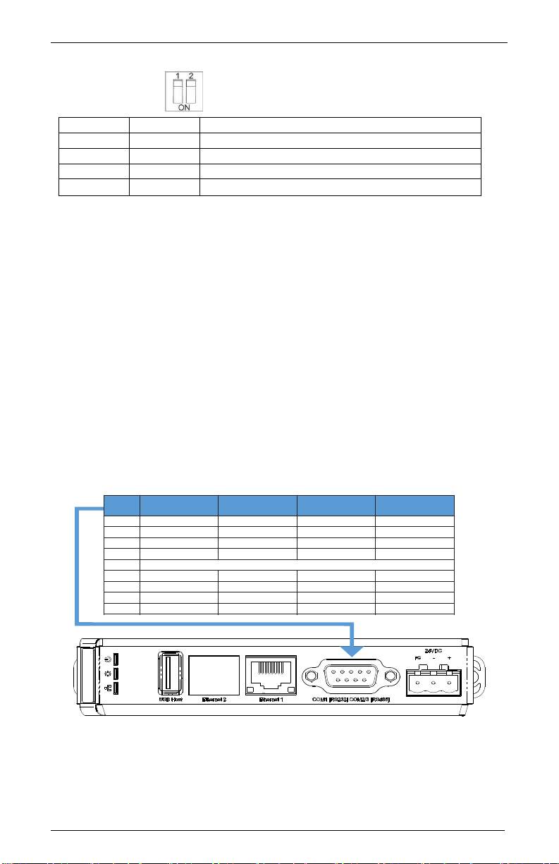
Serial Port Connections
The diagram below indicates the proper pin connections for the serial
ports of the RMI5001.
Figure 4: Serial Port Pinouts
Pin# COM1
[RS-232] COM2
[RS-485 2 wire] COM2
[RS-485 4 wire] COM3
[RS-485 2W]
1TX/RX+
2 RXD
3 TXD
4 TX/RX-
5 Signal Ground
6 TX/RX+ RX+
7 TX/RX- RX-
8 TX+
9 TX-
DE9P
Note: COM2 [RS-485 2W] and COM3 [RS-485 2W] support the Siemens MPI
187.5K multi-point interface. However, only one COM port can be used with the
Siemens MPI interface at a time.
DIP switches shown in the off position.

© 2016 Maple Systems Inc. All rights reserved.
Maple Systems Inc.
808 134th Street SW, Suite 120
Everett, WA 98204-7333
Phone: (425) 745-3229
Email: maple@maplesystems.com
Web: www.maplesystems.com
Table of contents
Other Maple Systems Recording Equipment manuals

Maple Systems
Maple Systems HMI5000B Series User manual

Maple Systems
Maple Systems HMC4043A-M Series User manual

Maple Systems
Maple Systems HMI5043L User manual

Maple Systems
Maple Systems HMI5097XL User manual

Maple Systems
Maple Systems HMI5043Lv2 User manual

Maple Systems
Maple Systems cMT3071 series User manual

Maple Systems
Maple Systems HMI5000P Series User manual


