Marani DPA240A User manual

User Manual
DPA240A

Described below are the functions of the front panel control buttons and encoders for the
DPA240A Speaker Processor.
• Getting Started
As soon as the DPA240A Speaker Processor is turned ON the device model name will appear in
the LCD screen:
and a status bar will show the progress of the DPA240A Speaker Processor initialization process:
After the first time activation, the DPA240A Speaker Processor will show on the LCD :
2IN4OUT
Default
2IN4OUT
2IN4OUT
2x4 SPEAKER PROCESSOR

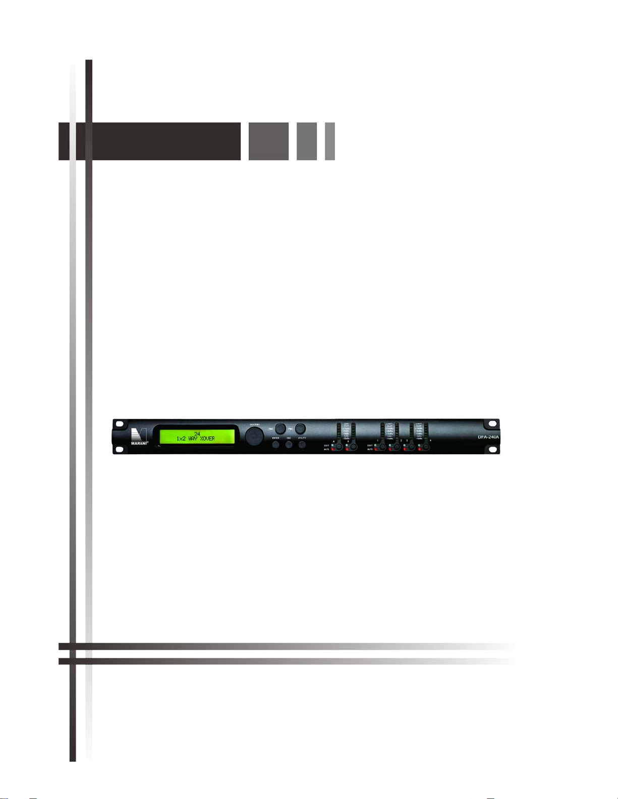
• Encoders and ENTER, ESC buttons
The DPA240A Speaker Processor is equipped with 3 Relative Encoders, “NAV/PM1”, “PM2” and
“PM3”, These encoders allow you to navigate the user interface and edit sections of the processor.
They allow the user to navigate within the screen for the selection of sub-menus, pages and
parameters and to select the values to be assigned during the editing operations.
The “ENTER” and “ESC” buttons allow the user to confirm or NOT confirm the operations
performed by the encoders.
• UTILITY, A/B and 1/2/3/4 buttons
The UTILITY button allows the User to enter the Sub-menus and set the general characteristics of
the Processor. The A and B buttons allow the User to enter the Editing Menus of the Processor's
Input Channels and buttons 1, 2, 3 and 4, allow the User to enter the Editing Menus of the
Processor's Output Channels.
The A and B buttons as well as the 1, 2, 3 and 4 buttons have double functions dependent on the
push and hold time.
When the A and B buttons are pushed and held for more than one second Input Channels A or B
are either muted or unmuted. The red LED will illuminate when the Channel is muted. When the
“MUTE” LED is OFF, then the related Input Channel is UN-MUTED.
A momentary push of the A and B buttons enters the Editing Mode for the Input Channels (see
later for the Input Channel Editing details).
The blue “EDIT” LED will now be ON.
When the 1, 2, 3 and 4 buttons are pushed and held for more than one second the Output
Channels 1, 2, 3, and 4 are either muted or unmuted. The red LED will illuminate when the
Channel is muted. When the “MUTE” LED is OFF, then the related Output Channel is UN-MUTED.
A momentary push of the 1, 2, 3 and 4 buttons enters the Editing Menu for the Output Channels
(see later for the Output Channel Editing details). The blue “EDIT” LED will now be ON.
• DPA240A Speaker Processor Menu and Sub-Menu Structures
As stated above, the start-up default screen is the following factory preset:
From this point, sub-menus are accessed and exited using the UTILITY”, “A/B”, “1/2/3/4”,
“ENTER” and “ESC” buttons and all parameters and values are navigated by the “NAV/PM1”,
“PM2” and “PM3” encoders. Please refer to the following menu structures:
2IN4OUT
Default

MENU “UTILITY MENU” [Access by pushing the “UTILITY” button]
NAV/PM1 Encoder PM2 or PM3 Encoder
[to navigate between menus] [to chose option, then ENTER to load it;
(*) indicates the selected option]
1 UTILITY MENU:......
<< System Utilities >>
1.1SYSTEM UTILITY: Input Source
<< Input Source >> Source = Analog input
Source = Digital Input
Source = Noise Gen
1.2SYSTEM UTILITY: Noise Generator
<< Noise Generator >> Type = Pink
Type = White
Lev = 0dB
:
Lev = -40dB
1.3SYSTEM UTILITY: Link Input L&R
<< Link Input L&R >> Link = Off
Link = On
1.4SYSTEM UTILITY: Delay Units
<< Delay Units >> Unit = Distance (m)
Unit = Time(ms)
1.5 SYSTEM UTILITY: Set Default Value
<< Set Default Value >> [Enter] to confirm
1.6 SYSTEM UTILITY: Firmware Version
<< Firmware Version >> Version = 2.0.3
2 UTILITY MENU:......
<< Program Utilities >>
2.1 PROGRAM UTILITY: Recall a Program
<< Recall a Program >> P01: Program empty
: :
P32 Program empty
2.2 PROGRAM UTILITY: Save a Program
<< Save a Program >> P01: Program empty
: :
P32: Program empty
2.3 PROGRAM UTILITY: Delete a Program
<< Delete a Program >> P01: Program empty
: :
P32: Program empty
3 UTILITY MENU:......
<< Interface Utilities >>
3.1 INTERFACE UTILITY: Interface Setup
Interface Setup Source = USB
Source = RS485 ID=1,…,32
4 UTILITY MENU:......
<< Security Utilities >>
4.1 SECURITY UTILITY: Parameter will
Show Parameter be shown
not be shown
4.2 SECURITY UTILITY: Lock Unit
Lock Unit Lock = Off
Lock = On
4.3 SECURITY UTILITY: Change Password
Change Password [ ]
4.4 SECURITY UTILITY: Enter Password
Lock With Password [ ]
ENTER
ESC
ENTER
ESC
ENTER
ESC
ENTER
ESC
ENTER
ESC
ENTER
ESC
ENTER
ESC
ENTER
ESC
ENTER
ESC
ENTER
ESC
ENTER
ESC
ENTER
ESC
ENTER
ESC
ENTER
ESC
ENTER
ESC
ENTER
ESC
ENTER
ESC
ENTER
ESC

MENU “Input A/B” Input Channels Editing[Access by pushing the “A/B” button]
NAV/PM1 Encoder NAV/PM1 Enc. PM2 Enc. PM3 Enc.
[to navigate between menus] [to chose values for the parameters, no need to confirm the chosen values,
which are automatically loaded during the encoders use]
1. Input A/B [Name] Name
Name = [Name]
-> Name = _ (For Editing the Device's Name, refer to the Details on the“Utility Menus Use” Section)
2. Input A/B [Name] N.Gate
Bypass=On
-> Bypass=On PM1 N/A. Byp=On/Off Thr=-80.0dBu …-50 dBu
Rel=10ms …1000ms Atk=1ms …1000ms
3. Input A/B Gain
Gain = + 0.0 dB
-> Gain = + 0.0 dB PM1 N/A. -18 dB 0.1dB
::
+12dB 0.9dB
Step 1dB Step 0.1dB
4. Input A/B Delay
Delay = 0.000 ms
-> Delay = 0.000 ms PM1 N/A. 000.0000mS 000.0000mS
[1 ms steps] [10.4 us steps]
480.0000mS 000.9984mS
5. Input A/B [Name] Phase
Phase=Normal
-> Phase=Normal PM1 N/A. Phase= Normal/Invert
6. Input A/B [Name] RMS Cmp
Bypass=On
-> Bypass=On PM1 N/A. Byp=On/Off
PM1 N/A. Threshold=+20dBu …-10dBu
PM1 N/A. Ratio =2:1 …32:1 Knee=0% … 100%
PM1 N/A. Rel=0.1sec …3.0sec Atk=5ms … 200ms
PM1 N/A. Make-up=-12dB …+12dB
7. Input A/B [Name] ALLPass-X (1 to 3 )
Bypass Freq=1000Hz
-> Bypass Freq=1000Hz PM1 N/A. Filter=Bypass/1st-order/2nd-order
PM1 N/A. Frequency=20Hz …20000Hz
Filter=2nd-order PM1 N/A. Q Factor=0.5 …9.9
8. Input A/B [Name] EQ Byp
Bypass=On
-> Bypass=On PM1 N/A. Bypass=On/Off
ENTER
ESC
ENTER
ESC
ENTER
ESC
ENTER
ESC
ENTER
ESC
ENTER
ESC
ENTER
ESC
ENTER
ESC

9. Input A/B [Name] PEQ-XX(00 to 30)
Byp=on Type=Peaking_Eq
-> Byp=on Type=Peaking_Eq PM1 N/A. Byp=On/Off Type=Peaking_Eq/ Hi -Shelv
1/ Hi -Shelv 2/ Hi -Shelv Q/ Lo-Shelv 1/ Lo-Shelv 2/Lo-Shelv Q/ Low-Pass 1/ Low-Pass 2/Low-Pass Q/High-Pass1/ High-Pass2/High-Pass Q/Band-Pass/ Notch
Type=Peaking_Eq PM1 N/A. Frequency=20Hz …20000Hz
PM1 N/A. Gain=-15dB …+15dB Q=0.4 …128
Type= Hi -Shelv 1/ Hi -Shelv 2 PM1 N/A. Frequency=20Hz …20000Hz
PM1 N/A. Gain=-15dB …+15dB Q=Fixed
Type= Hi -Shelv Q PM1 N/A. Frequency=20Hz …20000Hz
PM1 N/A. Gain=-15dB …+15dB Q=0.1 …5.1
Type= Lo-Shelv 1/ Lo-Shelv 2 PM1 N/A. Frequency=20Hz …20000Hz
PM1 N/A. Gain=-15dB …+15dB Q=Fixed
Type= Lo-Shelv Q PM1 N/A. Frequency=20Hz …20000Hz
PM1 N/A. Gain=-15dB …+15dB Q=0.1 …5.1
Type= Low-Pass 1/ Low-Pass 2 PM1 N/A. Frequency=20Hz …20000Hz
Type= Low-Pass Q PM1 N/A. Frequency=20Hz …20000Hz
PM1 N/A. Gain=-Fixed Q=0.1 …5.1
Type= High-Pass1/ High-Pass2 PM1 N/A. Frequency=20Hz …20000Hz
Type= High-Pass Q PM1 N/A. Frequency=20Hz …20000Hz
PM1 N/A. Gain=-Fixed Q=0.1 …5.1
Type= Band-Pass PM1 N/A. Frequency=20Hz …20000Hz
PM1 N/A. Gain=-15dB …+15dB Q=4 …104
Type= Notch PM1 N/A. Frequency=20Hz …20000Hz
PM1 N/A. Gain=Fixed Q=4 …104
ENTER
ESC

MENU “Output 1/2/3/4” Output Channels Editing [Access by pushing the “1/2/3/4” button]
NAV/PM1 Encoder NAV/PM1 Enc. PM2 Enc. PM3 Enc.
[to navigate between menus] [to chose values for the parameters, no need to confirm the chosen values,
which are automatically loaded during the encoders use]
1. Output[x] [Name] Name
Name = [Name]
-> Name = _ (For Editing the Device's Name, refer to the Details on the“Utility
Menus Use” Section)
2. Output[x] [Name] Source
Source = InA
->Source = InA PM1 N/A InA (Channel A) Same as PM2
InB (Channel B)
InA+InB (Channel A+ Channel B)
None
3. Output[x] [Name] Gain
Gain = + 0.0 dB
-> Gain = + 0.0 dB PM1 N/A -18 dB 0.1dB
::
+12dB 0.9dB
Step 1dB Step 0.1dB
4. Output[x] [Name] Delay
Delay = 0.000 ms
-> Delay = 0.000 ms PM1 N/A 000.0000mS 000.0000mS
[1 ms steps] [10.4 us steps]
270.0000mS 000.9984Ms
5. Output[x] [Name] Phase
Phase=Normal
-> Phase=Normal PM1 N/A. Phase= Normal/Invert Same as PM2
6. Output[x] [Name] Limiter
Bypass=On
-> Bypass=On PM1 N/A. Bypass= On/Off
PM1 N/A. Threshold=-10dBu …20 dBu
PM1 N/A. Rel=0.1sec …5sec Atk=1ms …900ms
7. Output[x] [Name] HPF
20.0 Hz Bypass
-> 20.0 Hz Bypass PM1 N/A [Freq.] 20Hz [Type/Slope] Bypass
: :
20kHz LR -48 dB /Oct
Slope=Bypass/ BW -6 dB/Oct / BW -12 dB/Oct / LR -12 dB/Oct / BS -12 dB/Oct / BW -18 dB/Oct / BW -24 dB/Oct / LR -24 dB/Oct / BS -24
dB/Oct / BW -36 dB/Oct / LR-36 dB/Oct / BW -48 dB/Oct / LR-48 dB/Oct /
8. Output[x] [Name] LPF
20.0 Hz Bypass
-> 20.0 Hz Bypass PM1 N/A [Freq.] 20Hz [Type/Slope] Bypass
: :
ENTER
ESC
ENTER
ESC
ENTER
ESC
ENTER
ESC
ENTER
ESC
ENTER
ESC
ENTER
ESC
ENTER
ESC

20kHz LR -48dB/Oct
Slope=Bypass/ BW -6 dB/Oct / BW -12 dB/Oct / LR -12 dB/Oct / BS -12 dB/Oct / BW -18 dB/Oct / BW -24 dB/Oct / LR -24 dB/Oct / BS -24
dB/Oct / BW -36 dB/Oct / LR-36 dB/Oct / BW -48 dB/Oct / LR-48 dB/Oct /
9. Output[x] [Name] EQ Byp
Bypass=On
-> Bypass=On PM1 N/A. Bypass=On/Off
10. Output[x] [Name] PEQ-XX(00 to 07)
Byp=on Type=Peaking_Eq
-> Byp=on Type=Peaking_Eq PM1 N/A. Byp=On/Off Type=Peaking_Eq/ Hi -Shelv
1/ Hi -Shelv 2/ Hi -Shelv Q/ Lo-Shelv 1/ Lo-Shelv 2/Lo-Shelv Q/ Low-Pass 1/ Low-Pass 2/Low-Pass Q/High-Pass1/ High-Pass2/High-Pass Q/Band-Pass/ Notch/ALL
Pass 1/ ALL Pass 2
Type=Peaking_Eq PM1 N/A. Frequency=20Hz …20000Hz
PM1 N/A. Gain=-15dB …+15dB Q=0.4 …128
Type= Hi -Shelv 1/ Hi -Shelv 2 PM1 N/A. Frequency=20Hz …20000Hz
PM1 N/A. Gain=-15dB …+15dB Q=Fixed
Type= Hi -Shelv Q PM1 N/A. Frequency=20Hz …20000Hz
PM1 N/A. Gain=-15dB …+15dB Q=0.1 …5.1
Type= Lo-Shelv 1/ Lo-Shelv 2 PM1 N/A. Frequency=20Hz …20000Hz
PM1 N/A. Gain=-15dB …+15dB Q=Fixed
Type= Lo-Shelv Q PM1 N/A. Frequency=20Hz …20000Hz
PM1 N/A. Gain=-15dB …+15dB Q=0.1 …5.1
Type= Low-Pass 1/ Low-Pass 2 PM1 N/A. Frequency=20Hz …20000Hz
Type= Low-Pass Q PM1 N/A. Frequency=20Hz …20000Hz
PM1 N/A. Gain=-Fixed Q=0.1 …5.1
Type= High-Pass1/ High-Pass2 PM1 N/A. Frequency=20Hz …20000Hz
Type= High-Pass Q PM1 N/A. Frequency=20Hz …20000Hz
PM1 N/A. Gain=-Fixed Q=0.1 …5.1
Type= Band-Pass PM1 N/A. Frequency=20Hz …20000Hz
PM1 N/A. Gain=-15dB …+15dB Q=4 …104
Type= Notch PM1 N/A. Frequency=20Hz …20000Hz
PM1 N/A. Gain=Fixed Q=4 …104
Type= ALL Pass 1 PM1 N/A. Frequency=20Hz …20000Hz
Type= ALL Pass 2 PM1 N/A. Frequency=20Hz …20000Hz
PM1 N/A. Gain=Fixed Q=4 …104
ENTER
ESC
ENTER
ESC

Menu “UTILITY” [access by pushing the “UTILITY” button]
From the “Default Screen”, it is possible access the “UTILITY” menu pushing the “UTILITY” button
and the Sub-Menus pages can be selected just rotating clockwise and counter-clockwise the
“NAV/PM1” encoder.
Once selected the sub-menu page, using the “ENTER” button can be accessed the Sub-Menus
pages, again “scrollable” using the “NAV/PM1” encoder and accessible for the parameters' editing
pushing again the “ENTER' button.
Through the “ESC” button, it is any time possible to go back to the action and page operation
preceding the “ENTER” button use.
Once inside the Sub-Menus pages, the several options can be scrolled by rotating the PM2 or PM3
encoders and selected/confirmed by pushing the “ENTER” button.
System Utilities Sub-menu – this sub-menu allows to access several operations related to the
DPA240A Speaker Management Start Up and General Configuration:
From the “System Utilities Sub-menu”, pushing “ENTER” and then using the “NAV/PM1” encoder
for scrolling will give access to the following pages:
−Input Source:the DPA240A Speaker Processor is equipped with 2 Analog Inputs (Balanced
Female XLR) and a stereo S/PDIF Digital Input (RCA connector).and noise generator
The “Input Source” page allows you to select the desired Input type:
By pressing ENTER on Input Source and then rotating the “PM2” or “PM3” encoders, it is
possible to select the Main Inputs for the DPA240A Speaker Processor, allowing the User to
choose between Analog , S/PDIF Digital or Noise Generator.
The selection can be confirmed by pressing the “ENTER” button.
The following screen shows that the Analog Input has been selected:
UTILITY MENU
--
System Utilities
--
SYSTEM UTILITY
-- Input Source --
Input Source
Source = Analog input

−Noise Generator:DPA240A Speaker Processor equips with 2 types of noise generator: White
Noise and Pink Noise.
By pressing ENTER and rotating the “PM2” encoder, it is possible to select between those 2
choice: “Pink” or “White”. By rotating the “PM3” encoder, it is possible to set the value of level
of white noise generator and pink noise generator, with whose range from 0dB to -40dB.
The following screen shows the selected pink noise with level of -20dB:
Link Input L&R: This page allows you to select the link function for input channel, making it
faster and more convenient for editing.
By pressing ENTER and rotating “PM2” or “PM3” encoder, it is possible to select between 2
selections: “ON” or “OFF”.
The following screen shows the selected “Link=On”:
By pressing ENTER button, the following screen shows an interface of confirm:
The following screen shows what happens if press ENTER one more time:
Wait about 1 sec to complete the setup successfully. Then the link for input channels is
activated.
Under “Link=On” status, when you edit either of the 2 input channels, the other one would be
edited accordingly.
−Delay Time/Distance: this page allows you to select the measurement unit to be used for
the Delays: Time (in milliseconds “ms”) or Distance (in meters “m”):
SYSTEM UTILITY
-- Delay Units --
SYSTEM UTILITY
-- Noise Generator --
Noise Generator
Type=Pink Lev=-20dB
SYSTEM UTILITY
-- Link Input L&R --
Link Input L&R
Link = On
Link:copy InL to InR
[Enter] to confirm
Link:copy InL to InR
Please wait………………….

By pressing ENTER button and rotating the “PM2” or “PM3” encoder, it is possible to select the
measurement unit to be used for the delay, which will be confirmed by pushing the ENTER
button.
The following screen shows the selected delay measurement is Time (milliseconds)
Set Default Value: All setting for DPA240A Speaker Processor can be set to default value:
By pressing ENTER button, will show up the following screen of an interface to confirm to set
the default value:
By pressing ENTER button one more time, will show up the following screen:
Wait around 3 sec for the processor set to the default value.
−Firmware Version: this page allows you to confirm the Software Version running on the
DPA240A Speaker Processor:
The correct Software Version is “V2.0.3”
Delay Units
Unit : = Time (ms) *
SYSTEM UTILITY
-- Firmware Version --
SYSTEM UTILITY
-- Set Default Value --
Set Default Value
[Enter] to confirm
Set Default Value
Wait : loading default….

Program Utilities Sub-menu – this sub-menu allows you to access several options related to
the DPA240A Speaker Processor operating mode and to manage the presets stored and recallable
within the Unit:
By pressing the ENTER button and then using the “NAV/PM1” encoder to scroll, the following
pages can be accessed:
−Recall a Program: this page allows the Loading of a preset program. You can store up to 32
presets in the DPA240A Speaker Processor memory:
By pressing ENTER and rotating the “NAV/PM1” encoders, it is possible to scroll through all
current available presets.
If NO USER PRESETS are stored yet, the screen will show the following:
If presets have previously been stored by the user, anyone of them can be recalled:
By using the “NAV/PM1” encoder it is possible to scroll through the stored presets. Once the
desired preset appears on the screen, select it by pressing the “ENTER” button and this will
force the DPA240A Speaker Processor to begin to load this selected preset and the following
transitory screen will appear:
Once loaded the DPA240A Speaker Processor will exit to the “Recall a Program” screen
automatically and the above screen will disappear:
Note: at any time it is possible to quit the recalling action by pressing the “ESC” button.
Recall a Program
No Stored Programs
[ENTER] to Recall.
P01: PRESET 1
Loading New Program ......
P01: PRESET 1
PROGRAM UTILITY
-- Recall a Program --
UTILITY MENU
-- Program Utilities --
PROGRAM UTILITY
-Recall a Program -

−Save a Program: this page allows you to store a new preset in the DPA240A Speaker
Processor’s memory:
By pressing the ENTER button and rotating the “NAV/PM1” encoder, it is possible to scroll
through the previously saved presets or the available empty locations (identified by “Program
empty”).
If no user presets are stored, the “Save a Program” screen will show empty memory locations
for all 1-32 presets as shown in the example below for location 10:
When storing an edited configuration for the DPA240A Speaker Processor, select the location
for a preset from the 32 available by using the “NAV/PM1” encoders.
Once the desired location appears on the screen press ENTER button again to reach the “Edit
Program Name” page.
In this page the User can enter a Preset Name (up to 16 Characters) by using the “PM3”
encoder to choose a character and the “PM2” encoder to move between the 16 available
locations for the character’s positioning.
The current position of the cursor is shown by a “blinking underscore”.
The following is an example of a screen while entering the preset name “Stage 1 2x2” in
location 10:
To store the Preset Name press the “ENTER” button again.
The above action will take you to the “Enter to Save” page showing the selected location for
the preset and the final edited name:
Pressing “ENTER” again, will store the preset in the selected location with the chosen name
and the following transitory screen will appear on the LCD:
Save a Program
P10: Empty Memory
Edit Program Name.
P10: Stage 1 2x2
Saving to Memory.....
P10: Stage 1 2x2
PROGRAM UTILITY
-- Save a Program
--
[Enter] to Save
P10: Stage 1 2x2

Once the preset is stored, the above screen will disappear returning to the following screen:
If during the Preset Storing process you want to overwrite an existing memory location select
this location in the “Set Program Name” page, then press ENTER button and you will be
asked if you want to overwrite this preset with the following “[ENTER] to Overwrite” screen
displaying the currently stored preset and location:
If you wish to proceed press “ENTER” again and the DPA240A Speaker Processor will go ahead
with the “Set Program Name” page and the subsequent overwrite on completion of the
previously described storing process..
Note: at any time it is possible to quit the storing action by pressing the “ESC” button.
−Delete a Program: this page allows you to delete a preset already stored in the DPA240A
Speaker Processor memory:
By pressing the ENTER button and rotating the “NAV/PM1” encoder, it is possible to scroll
through the previously saved presets and the available empty locations (identified by
“Program empty”).
If no user presets are stored, the “Delete a Program” screen will show empty memory
locations for all 1-32 presets as shown in the example below for location 10:
If Presets are available they will be shown in the “Delete a Program” page as follows:
By using the “NAV/PM1” encoder it is possible to select a preset to be deleted.
Pressing the “ENTER” button on a selected preset will bring up the “[Enter] to Delete.” page
showing the selected preset.
Delete a Program
P10: Stage 1 2x2
PROGRAM UTILITY
-- Save a Program --
[Enter] to Overwrite
P10: Stage 1 2x2
PROGRAM UTILITY
-- Delete a Program --
Delete a Program
P10: Program empty

For example, if we want to delete the preset 10, “Stage 1 2x2”, the screen will be the
following:
Confirming the deletion by pressing “ENTER” again, will force the DPA240A Speaker Processor
to erase the selected preset and the following transitory screen will appear:
Once the preset is deleted, the above screen will disappear returning to the following screen:
Note: At any time it is possible to quit the deleting action by pressing the “ESC” button.
Interface Utilities Sub-menu – this sub-menu allows you to define the remote control interface
[USB or RS485] to be used for controlling the DPA240A Speaker Processor:
From “Interface Utilities”, press “ENTER” button to access the Interface Setup.
−Interface Setup: this screen allows you to choose the communication source for the
DPA240A Speaker Processors.
By pressing “ENTER” and then using the PM2 encoder you can choose between the two
possible interfaces (USB or RS485) for the DPA240A Speaker Processor.
If select RS485, select the ID by using “PM3” encoder, whose range from 01 to 32.
The following screen displaying the currently selected interface as RS485:
[ENTER] to Delete.
P10: Stage 1 2x2
Deleting Program......
P10: Stage 1 2x2
Interface Setup
Source=RS485 ID=01
PROGRAM UTILITY
-- Delete a Progra --
UTILITY MENU
-- Interface Utilities --
INTERFACE Setup
Source=USB

Security Sub-menu – this sub-menu allows the User to set the parameters shown, lock the
DPA240A Speaker Processor and set a Password therefore limiting the unit's functions and
controls to those who have only access to the appropriate Password.
Press ENTER and then use the “NAV/PM1” encoder to scroll between options.
−Show Parameter: Pressing ENTER button from the above menu will access the “Show
Parameter” Sub Menu
Press ENTER button again and use the PM2 or PM3 encoders to select between “be shown” or
“not be shown” options.
Choosing the “be shown” option means that once the unit is locked, you cannot access
parameter editing features, but they will be displayed on the LCD screen.
Choosing the “not be shown” option means that once the unit is locked, the parameters will
not be shown at all. With this option, when trying to access a parameter, the following
screen message will appear:
−Lock Unit: this sub-menu allows the user to lock the device so no parameters can be edited
or modified.
When the Unit is in an unlocked condition, all parameters will be available for editing. When
you select On, all parameters will be locked and are not available for editing.
When you select lock from the menu, the unit will be locked and the lock menu automatically
exited. The screen will revert to the “Default” showing the current XOVER configuration and
the preset selected and beside the preset’s name a “keylock” icon indicating that the DPA240A
Speaker Processor is locked.
UTILITY MENU
-- Security Utilities --
SECURITY UTILITY
-- Show Parameter --
Parameter will
not be shown
SECURITY UTILITY
-- Lock Unit --
Lock Unit
Lock : On

−Change Password: from the “Change Password” sub-menu:
Press “ENTER” to access the “Change Password” page:
Use the PM2 encoder to move between available locations, and the PM3 encoder to choose a
character. The current position of the cursor for the characters to be entered is shown by a
“blinking underscore”.
Input the original password “000000” for the DPA240A Speaker Processor, and press ENTER
button, will access to the “New Password” Page. Use the PM2 encoder to move between
available locations, and rotate the PM3 encoder to edit a 6-position new password.
The following screen is the example with the new password after edition is “111111”
Press the ENTER button again, will access the “Confirm password” page, use the “PM2”
encoder to move between available locations and rotate “PM3” encoder to choose a character,
input the new password edited just now.
The following screen is the example with typing in new password “111111” edited just now.
Press the ENTER button one more time, the new password will be set successfully.
Change Password
[_ ]
Confirm Password
[111111]
SECURITY UTILITY
-- Change Password
Change Password
[ ]
New Password
[111111]

−Lock With Password: from the “Lock With Password” sub-menu:
There’s limitation to the editing function if the DPA240A Speaker Processor is locked with
password. All functions for this unit are banned, including MUTE A/B and MUTE 1/2/3/4 buttons.
Press “ENTER” to gain access to the “Enter Password” screen:
Use the “PM2” encoder to move between available locations, and rotate “PM3” encoder to select
characters. If the password of this DPA240A Speaker Processor never modified, input the default
password “000000”, the unit will be locked. In this case, default screen will show a “Key” icon,
user cannot enter into the sub-menu, unless he holds the password.
SECURITY UTILITY
-- Lock With Password --
Enter Password
[ ]

Menu “Input A/B” Input Channels Editing [access by pushing the “A/B” buttons]
From the “Default Screen”, it is possible to access the “Input A/B” menu by pushing the “A” or “B”
button. Once the button is pressed, the related blue “EDIT” LED will turn ON. The Sub-Menu
pages can now be scrolled through by rotating clockwise and counter-clockwise the “NAV/PM1”
encoder.
For parameter editing it is necessary to press ENTER button and an arrow will appear on the left
of the screen “->”. Then use the “PM2” and “PM3” encoders for editing and setting the
parameter values. On some parameters that have three independent values, you will also need to
use the PM1 encoder, eg filter parameter settings.
Note: All options can be done using the “NAV/PM1”, “PM2”, and “PM3” encoders and the current
shown value of the selected option is AUTOMATICALLY loaded during the encoders' use and stored
as the current value once leaving the page.
Audio Signal Input (A/B) Path Block Scheme
Name page – from this screen, it is possible to assign input channel a name with 6 characters
For example, name the Input A as “In L” in the Name Page:
By pressing ENTER in the Name page, user can edit the name, and there will be an arrow, as the
following screen shows:
The first character will flash.
Select character from these 6 positions by rotating “PM2” encoder and choose the desired
characters by rotating “PM3” encoder. Once the new name is defined, for example, “In A”, confirm
this new name by pressing ENTER… A new name will display on the screen, after replaced the old
one.
The following screen is shown with the new name “In A”, by replacing the previous one “In L”
N.Gate page– from this page, it is possible to set the Input Channels Noise Gate. Noise gate can
be set as “ON” or “OFF” status. The following screen is the selected “ON” status:
InputA: In L Name
Name = In L
InputA: In L Name
->Name = In L
InputA: In A Name
Name = In A

By pressing ENTER button in this page, an arrow “->” will show up on the left of the screen, and
enter into the setting interface 1 of the noise gate:
By using the “PM2” encoder, it is possible to set the noise gate as “ON” or “OFF”. By using the
“PM3” encoder, it is possible to select its attack threshold from -80dBu to -50dBu.
By rotating “NAV/PM1” encoder, user can enter into the setting interface 2 of the noise gate:
By using “PM2” encoder, user can set noise gate release time: from 10ms to 1000ms, and using
“PM3” encoder to set noise gate attack time: from 1ms to 1000ms.
Gain page – from this screen it is possible to set the Input Channels Level from -18dB to +12dB,
press ENTER button, an arrow will appear on the left of the screen “->” then use the “PM2” or
“PM3” to set parameters.
The value set on this screen will only affect the input level of the selected Channel A or B.
The following is an example screen for the “Gain” page that has set the Gain of Input Channel A to
+0.0dB:
Delay page – from this page it is possible to set the Input Channels Delay Time from
000.0000mS up to 848.9984mS, by steps of 1mS or 10.4uS.
To set the Delay time press ENTER, an arrow will appear on the left of the screen “->”. then use
the “PM2” encoder to set the Delay Time in steps of 1mS and the “PM3” for setting the “fine”
Delay Time in steps of 10.4 microseconds.
The following is an example screen for the “Delay” page where the Delay Time of Input Channel A
is set to 160.1872mS:
Phase page– from this page, it is possible to set input channels phase as “Normal” or “Invert”.
The following is an example screen of “Normal” Phase:
Input-A Name Gain
-
> Gain = + 0.0dB
Input-A Name Delay
-
> Delay = 160.1872mS
InputA: Name N.Gate
->Byp=On Thr=-80.0dBu
InputA: Name N.Gate
Bypass = On
InputA: Name N.Gate
->Rel=50ms Atk=3ms
Table of contents
Other Marani Recording Equipment manuals