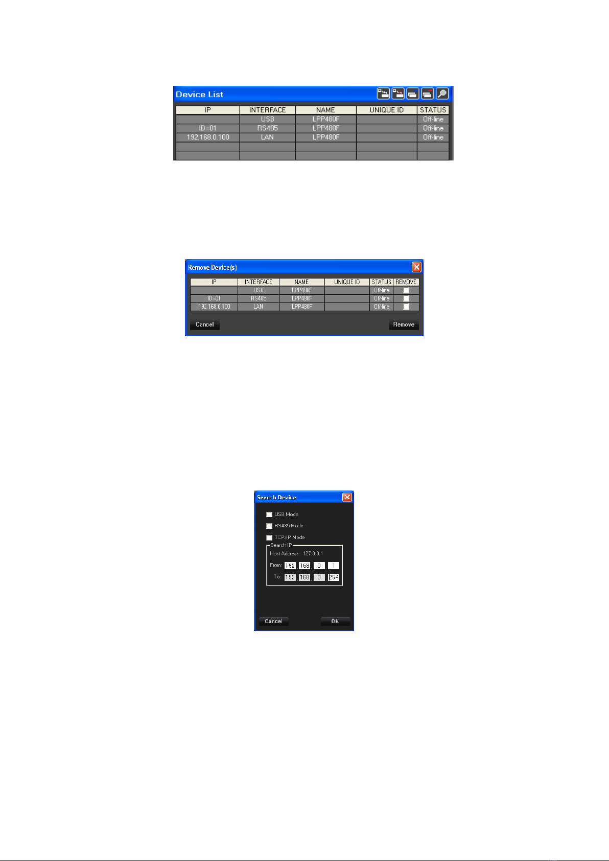
If the TCP/IP check-box is selected then the system search all device connect via LAN mode with
IP on the range selected by User, the system can search devices from 1 to max 255 for time, in that
case the first 3 byte of the IP address of the “From” and “To” are the same.
If the Host Address is not found (PC have the LAN not available) then the sw PC show the IP
address :127.0.0.1 and in that case is not possible search device in TCP/IP mode.
After selected the search mode check-box press the button “Ok” and the system start to interrogate
the network and when finish show the new device found on the Device-List or show a pop-up
message with “No new device(s) found”.
Connect/Disconnect ALL: with the button “Connect/Disconnect All”
is possible to connect (set in On-line mode) all device present on the Device-List in Off-line Mode
is possible to disconnect (set in Off-line mode) all device present on the Device-List in On-line
Mode
Single Connection
if the device 's STATUS is On-line then if the User click on the colum “STATUS” of the device's
row then the device switch in Off-line mode after a confirmation, vice versa if the device is Off-
line then switch in On-line mode.
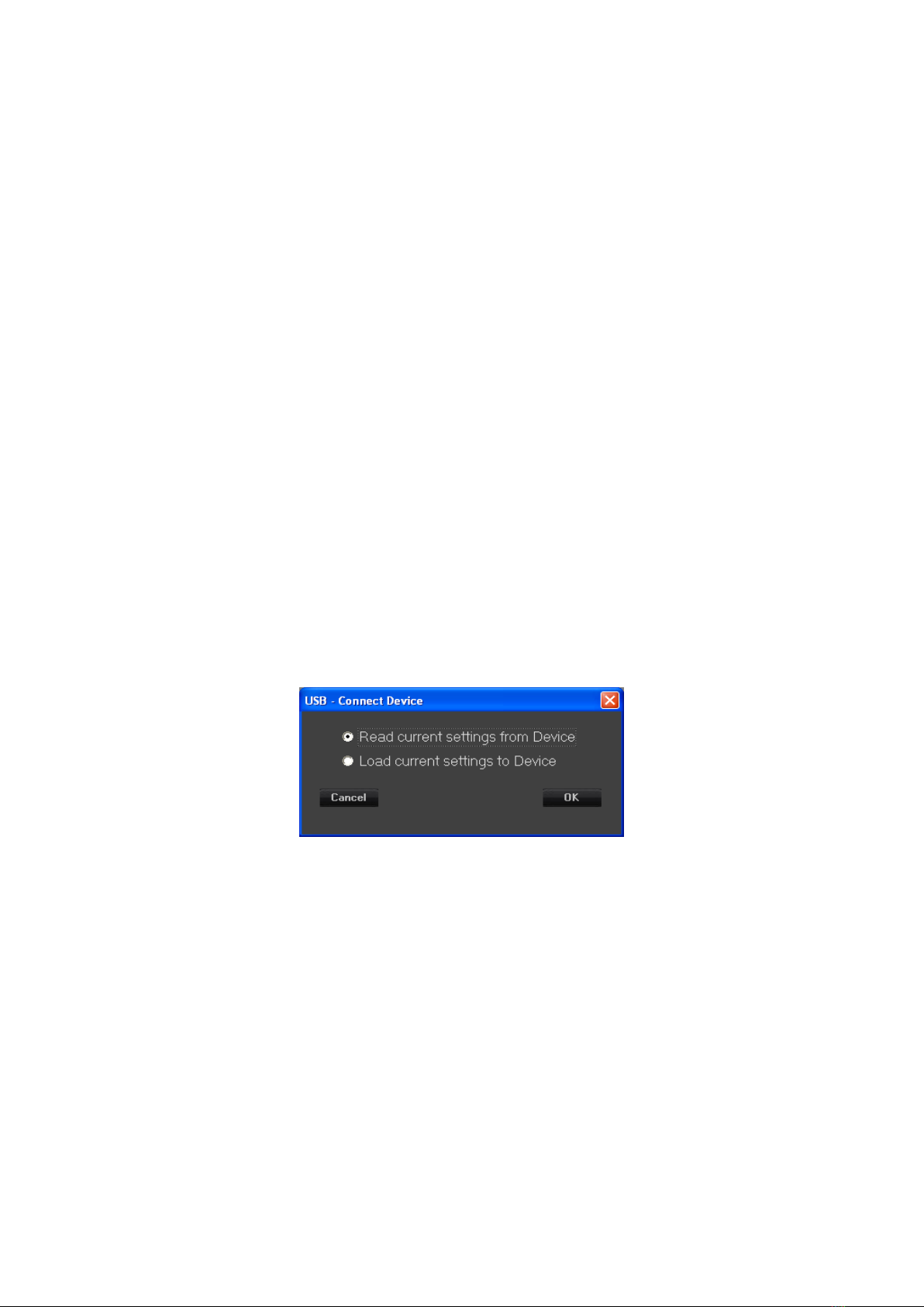
To switch from Off-line to On-line mode the system ask to User if:
a. the GUI (Graphic User Interface) must be update with the data present on the device or
b. the Device must be update with the data already edit on the GUI (data of the device selected and
already present on the project).
This window will be show also when the User use the button “Connect All”
After press the Button “OK” the system run the selected option set by User.
If the device selected is on the network then on the Device-List will be show the device status “On-
Line”.
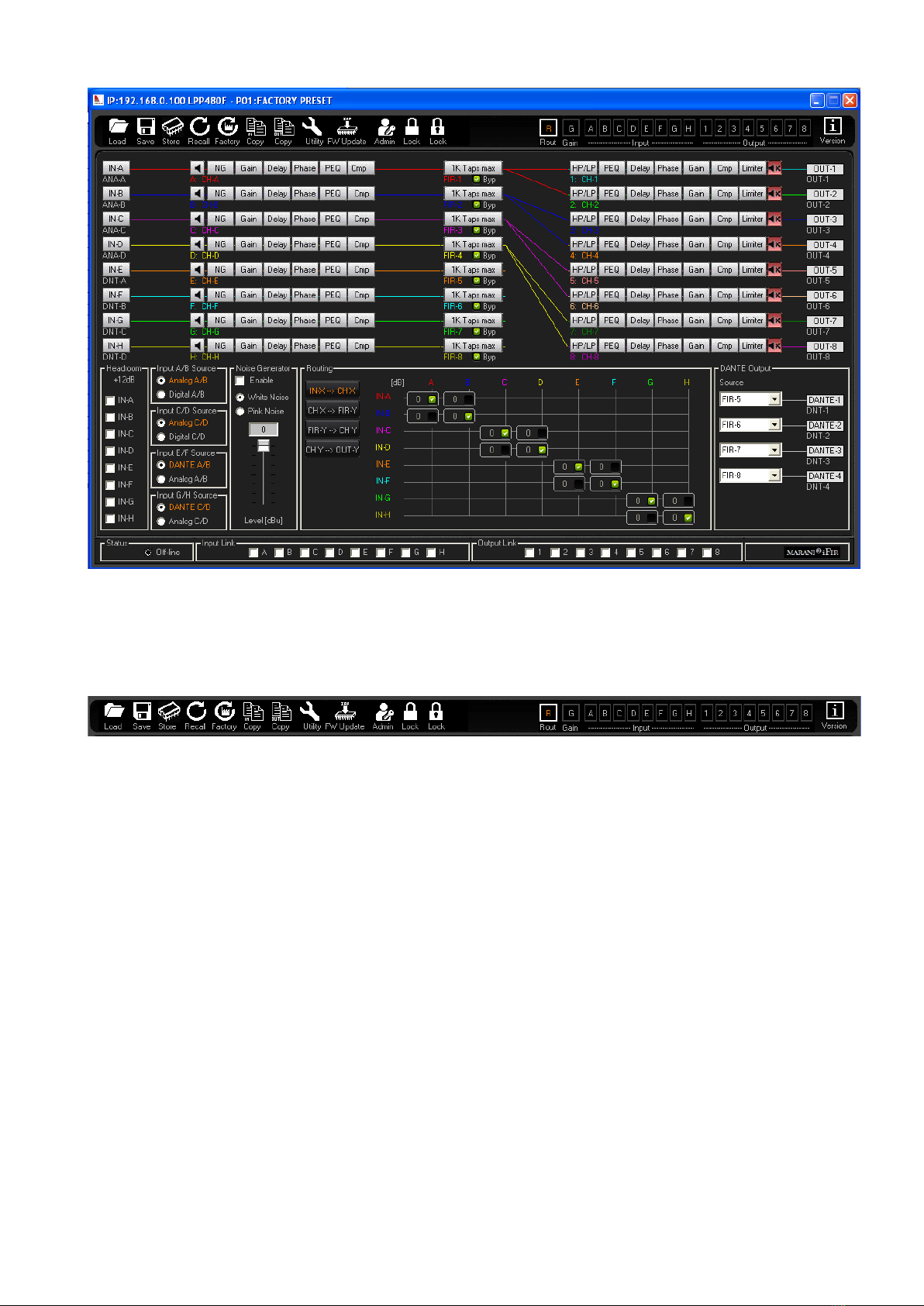
EDIT DEVICE
The user can edit the configuration of the device in Off-line and On-line mode. If the Device is in
On-line mode then the changed parameters will be update on the device in real-time mode.
To Edit a device the user must a double-click with mouse in the device-List on the column IP (or
Interface, or Name or Unique ID) of the device's row.
After the double-click the system show the following Edit window