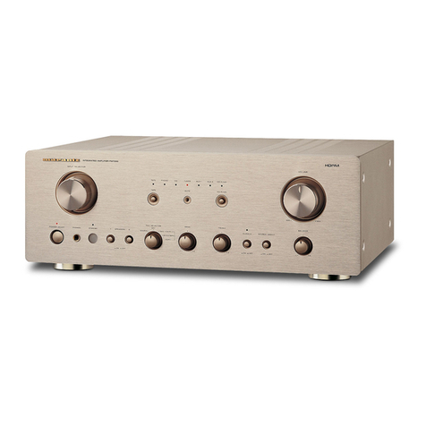
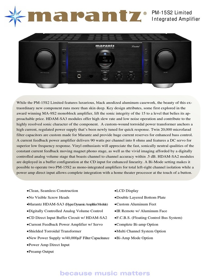
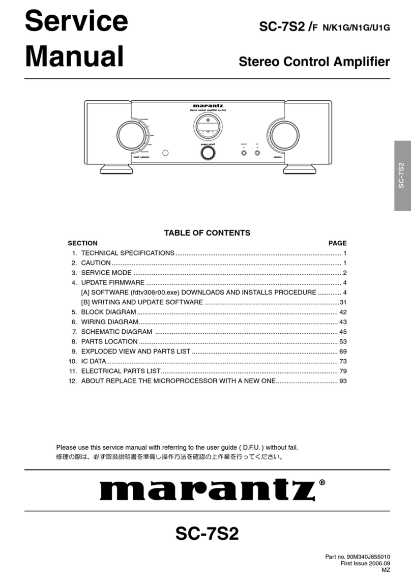
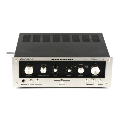
Marantz PM-11S2 User manual

PM-11S2
Please use this service manual with referring to the user guide ( D.F.U. ) without fail.
Service
Manual
PM-11S2
PM-11S2 /F N/K1G/N1G/U1G
/N1S
Part no. 90M04AJ855020
First Issue 2008.08
MZ
Integrated Amplifier
TABLE OF CONTENTS
SECTION PAGE
1. TECHNICAL SPECIFICATIONS ........................................................................................... 1
2. CAUTION .............................................................................................................................. 1
3. ALIGNMENTS....................................................................................................................... 2
4. SERVICE MODE / TRIM CHECK MODE.............................................................................. 4
5. PROTECTION MODE ........................................................................................................... 8
6. UPDATE FIRMWARE.......................................................................................................... 10
[A] SOFTWARE DOWNLOADS AND INSTALLS PROCEDURE ........................................ 10
[B] WRITING AND UPDATE SOFTWARE .......................................................................... 26
7. WIRING DIAGRAM ............................................................................................................. 37
8. BLOCK DIAGRAM .............................................................................................................. 39
9. SCHEMATIC DIAGRAM...................................................................................................... 41
10. PARTS LOCATION.............................................................................................................. 55
11. EXPLODED VIEW AND PARTS LIST................................................................................. 71
12. MICROPROCESSOR AND IC DATA................................................................................... 76
13. ELECTRICAL PARTS LIST................................................................................................. 83
14. ABOUT REPLACE THE MICROPROCESSOR WITH A NEW ONE............................. 107
POWER ON/OFF
PHONES
VOLUME
A
TONE
SPEAKER
B
SPEAKER
REC OUT
PRE OUT
ATT.
MC
OPERATE
PHONO
DISPLAY
SELECTOR
INPUT

安全上の注意:
がついている部品は、安全上重要な部品です。必ず指定されている部品番号のものを使用して下さい。
MARANTZ DESIGN AND SERVICE
Using superior design and selected high grade components, MARANTZ company has created the ultimate in stereo sound.
Only original MARANTZ parts can insure that your MARANTZ product will continue to perform to the specifications for which
it is famous.
Parts for your MARANTZ equipment are generally available to our National Marantz Subsidiary or Agent.
ORDERING PARTS :
Parts can be ordered either by mail or by Fax.. In both cases, the correct part number has to be specified.
The following information must be supplied to eliminate delays in processing your order :
1. Complete address
2. Complete part numbers and quantities required
3. Description of parts
4. Model number for which part is required
5. Way of shipment
6. Signature : any order form or Fax. must be signed, otherwise such part order will be considered as null and void.
SHOCK, FIRE HAZARD SERVICE TEST :
CAUTION : After servicing this appliance and prior to returning to customer, measure the resistance between either primary AC
cord connector pins ( with unit NOT connected to AC mains and its Power switch ON ), and the face or Front Panel of product
and controls and chassis bottom.
Any resistance measurement less than 1 Megohms should cause unit to be repaired or corrected before AC power is applied,
and verified before it is return to the user/customer.
Ref. UL Standard No. 60065.
In case of difficulties, do not hesitate to contact the Technical
Department at above mentioned address.
080702MZ
USA
MARANTZ AMERICA, INC
100 CORPORATE DRIVE
MAHWAH, NEW JERSEY 07430
USA
EUROPE / TRADING
D&M EUROPE B. V.
P. O. BOX 8744, BUILDING SILVERPOINT
BEEMDSTRAAT 11, 5653 MA EINDHOVEN
THE NETHERLANDS
PHONE : +31 - 40 - 2507844
FAX : +31 - 40 - 2507860
KOREA
D&M SALES AND MARKETING KOREA LTD.
CHUNG JIN B/D., #1001,
53-5, WONHYORO 3 GA, YONGSAN-GU,
SEOUL, 140-719, KOREA
PHONE : +82 - 2 - 323 - 2155
FAX : +82 - 2 - 323 - 2154
CANADA
D&M Canada Inc.
5-505 APPLE CREEK BLVD.
MARKHAM, ONTARIO L3R 5B1
CANADA
PHONE : 905 - 415 - 9292
FAX : 905 - 475 - 4159
JAPAN
D&M BUILDING, 2-1 NISSHIN-CHO,
KAWASAKI-KU, KAWASAKI-SHI,
KANAGAWA, 210-8569 JAPAN
D&M Holdings Inc.
CHINA
D&M SALES AND MARKETING SHANGHAI LTD.
ROOM.808 SHANGHAI AIRPORT CITY TERMINAL
NO.1600 NANJING (WEST) ROAD, SHANGHAI,
CHINA. 200040
TEL : 021 - 6248 - 5151
FAX : 021 - 6248 - 4434
NOTE ON SAFETY :
Symbol Fire or electrical shock hazard. Only original parts should be used to replaced any part marked with symbol .
Any other component substitution (other than original type), may increase risk of fire or electrical shock hazard.

1
27
NAMES AND FUNCTIONSBASIC CONNECTIONSBASIC OPERATIONS
ADVANCED CONNECTIONS
ADVANCED OPERATIONSTROUBLESHOOTINGOTHERSOTHERS
ENGLISH
OTHERS
SPECIFICATIONS &
DIMENSIONAL DRAWINGS
Power output
(20 Hz – 20 kHz simultaneous drive of both channels)
.....................................................100W x 2 (81load)
.....................................................200W x 2 (41load)
Total frequency distortion
(20Hz – 20kHz simultaneous drive of both channels, 81load)
..........................................................................0.01%
Output band width (81load, 0.05%) .................. 5Hz ~50kHz
Frequency response (CD, 1W, 81load)..5Hz ~ 120kHz±3dB
Dumping factor (81load, 20Hz – 20kHz).........................100
Input sensitivity/Input impedance
PHONO (MC)................................................270µV/1001
PHONO (MM) ..................................................3mV/47k1
BALANCED .................................................480mV/20k1
CD/LINE.......................................................240mV/20k1
Output voltage/Output impedance
PRE OUT........................................................1.9 V/2201
Maximum allowed PHONO input (1kHz)
MC .......................................................................... 12mV
MM........................................................................ 130mV
RIAA deviation (20Hz ~ 20kHz) ............................ ±0.5dB
S/N (IHF-A, 1W, 81load)
PHONO (MC).....................................76dB (0.5mV input)
PHONO (MM) .......................................90dB (5mV input)
BALANCED .............................................95dB (1V input)
CD/LINE............................................96dB (500mV input)
Tone control
Bass (50Hz) ............................................................. ±8dB
Treble (20kHz).......................................................... ±8dB
Power requirement
...............................................AC 120V 60Hz (U.S.A.)
........................................ AC 230V 50/60Hz (Europe)
Power consumption
(EN60065 7th Ed.) .................................................. 300W
(UL60065)............................................................... 300W
Accessories
Remote controller ...........................................................1
AAA batteries..................................................................2
Detachable AC power cable............................................1
Maximum outer dimensions (Amp)
Width................................................17-3/8 ins. (440 mm)
Height ................................................6-5/8 ins. (168 mm)
Depth ...............................................17-1/2 ins. (444 mm)
Weight (Amp).............................................. 58.6 lbs (26.6 kg)
POWERON/OFF
PHONES
VOLUME
A
TONE
SPEAKER
B
SPEAKER
RECOUT
PREOUT
ATT.
MC
OPERATE
PHONO
DISPLAY
SELECTOR
INPUT
6-5/8 (168)
3/16 (4)
5-3/4 (146)
3/4 (18)
17-3/8 (440)
17-1/2 (444)
3/4 (19)
1
(25)
15-3/4 (400)
Unit: inch (mm)
Specifications subject to change without prior notice.
PM-11S2UN01Eng.indd27 08.8.76:42:24PM
1. TECHNICAL SPECIFICATIONS
Power output
(20 Hz – 20 kHz simultaneous drive of both channels)
8 Ωload ............................................................100 W x 2
4 Ωload ............................................................200 W x 2
Total frequency distortion
(20 Hz – 20 kHz simultaneous drive of both channels, 8 Ωload)...0.01 %
Output band width (8 Ωload, 0.05 %) ............. 5 Hz – 50 kHz
Frequency response (CD, 1 W, 8 Ωload)
................................................5 Hz – 120 kHz ± 3 dB
Dumping factor (8 Ωload, 20 Hz – 20 kHz)......................100
Input sensitivity/Input impedance
PHONO (MC)..............................................270 µV/100 Ω
PHONO (MM) ................................................3 mV/47 kΩ
BALANCED .............................................. 480 mV/20 kΩ
CD/LINE.................................................... 240 mV/20 kΩ
Output voltage/Output impedance
PRE OUT.......................................................1.9 V/220 Ω
Maximum allowed PHONO input (1 kHz)
MC ......................................................................... 12 mV
MM....................................................................... 130 mV
RIAA deviation (20 Hz – 20 kHz) ........................ ± 0.5 dB
S/N (IHF-A, 1 W, 8 Ωload)
PHONO (MC : 0.5 mV input)................................... 76 dB
PHONO (MM : 5 mV input) ..................................... 90 dB
BALANCED : 500 mV input .................................... 95 dB
CD/LINE : 500 mV input.......................................... 96 dB
Tone control
Bass (50 Hz) .......................................................... ± 8 dB
Treble (20 kHz)....................................................... ± 8 dB
Power requirement
[/F] ................................................ AC 100 V 50/60 Hz
[/K]...................................................... AC 220V 50 Hz
[/N]................................................ AC 230 V 50/60 Hz
[/U]..................................................... AC 120 V 60 Hz
Power consumption
J60065/EN60065 7th Ed./UL60065 ........................300 W
Accessories
Remote controller (RC-11PMS1)....................................1
AAA batteries..................................................................2
Detachable AC power cable............................................1
Maximum outer dimensions (Amp)
Width.................................................. 17-3/8 in (440 mm)
Height .................................................. 6-5/8 in (168 mm)
Depth ................................................. 17-1/2 in (444 mm)
Weight (Amp)................................................58.6 lb (26.6 kg)
2. CAUTION
The layout of this amplifier is well concerned for sound quality.
1. When screws and washers are removed, those parts must
be set to the same places.
2. When wires are removed, the wires must be installed in the
same roots, same places.
3. Do not hold the side panel (013D) to move the unit when
the unit is disassembled.
2. 注意
当機は音質を考慮したレイアウトになっています。
1. ネジやワッシャ類を取り外した場合、元の位置に取り付け
てください。
2. ワイヤ類を取り外した場合の配線ルートは、元のルート通
りに戻してください。
3. 当機を分解した状態で移動するときは、サイドパネル
(013D)を持たないでください。

2
AC IN
3
1
2
3
1
2
POWERON/OFF
PHONES
VOLUME
A
TONE
SPEAKER
B
SPEAKER
REC OUT
PRE OUT
ATT.
MC
OPERATE
PHONO
DISPLAY
SELECTOR
INPUT
Digital Voltmeter
R ch
POWER ON/OFF VOLUMESPEAKERS A
V
Digital Voltmeter
L ch
V
P701 (R ch) P601 (L ch)
R629
R729
3. ALIGNMENTS
Adjustment Procedure
Set the power voltage to rated voltage for this adjustment
DC Offset Voltage Adjustment
1. Before turning on the power,
Insert Digital Voltage Meter between the SPEAKER
SYSTEMS A (L CH) "+" and "–".
Insert Digital Voltage Meter between the SPEAKER
SYSTEMS A (R CH) "+" and "–".
2. Turn on the power, VOLUME is set as -∞.
3. Press the SPEAKER A button.
4. After turn on the power and 2 minutes pass, first L CH is
adjusted.
The variable resistor R629 on P601 is turned with
adjustment driver, and the Digital Voltage Meter is
adjusted to "0 mV ± 10 mV".
5. Then, R CH is adjusted.
The variable resistor R729 on P701 is turned with
adjustment driver, and the Digital Voltage Meter is
adjusted to "0 mV ± 10 mV".
6. Although after-adjustment DC offset voltage has some
change, Please check that the range of DC offset voltage
between L ch (R ch) "+" and L ch (R ch) "-" terminal of
SPEAKER SYSTEMS A is "0 mV ± 20 mV".
P701(R ch) P601(L ch)
R729 R629
調整手順
調整時は必ず電源電圧を定格電圧に合わせてください。
DCオフセット電圧調整
1. 電源をONする前にリアパネルのSPEAKER SYATEMS Aの
L CHおよびR CHそれぞれの"+"端子と"-"端子間にデジタル
ボルトメーターを接続します。
2. 電源を投入しボリュームを-∞にします。
3. SPEAKERS AのボタンをONにします。
4. 電源を投入して"2分"経過後、最初にL CHを調整します。
P601基板の半固定抵抗R629を調整ドライバーで回し、L
CHスピーカー出力端子に接続したデジタルボルトメーター
の電圧が"0 mV ±10 mV"以内になるように調整します。
5. 続けて、R CHを調整します。P701基板の半固定抵抗R729
を調整ドライバーで回し、R CHスピーカー出力端子に接続
したデジタルボルトメーターの電圧が"0 mV ±10 mV"以
内になるように調整します。
6. 調整後DCオフセット電圧は多少の変動はありますが、
SPEAKER SYSTEMS A のL CH および R CH それぞれ
の"+"端子と"-"端子間のDCオフセット電圧は
"0 mV ±20 mV"の範囲であることを確認してください。

3
Digital Voltmeter
V
Digital Voltmeter
V
Idling Current Adjustment
1. After DC Offset Voltage Adjustment is completed, adjust
the Idling Current with the variable resistor R633 and
R733 on the PWB (P601/P701).
2. Turn off the power.
3. "+" of Connect Digital Voltage is connected to the No. 1
pin and connected "–" to No. 3 pin of J653.
4. "+" of Connect Digital Voltage is connected to the No. 1
pin and connected "–" to No. 3 pin of J753.
5. Before turning on the power, R633 and R733 have been
counter clockwise turned with the adjustment driver.
6. Turn on the power, VOLUME is set as -∞.
7. With seeing the digital voltage meter turn the variable
resister clockwise slowly to adjust the idling current.
• IdlingadjustmentwithR633 (R733).
• TurnR633 (R733) clockwise to increase the idling
current.
• Theadjustmentvalueofidlingcurrentis
"9.6 mV(48 mA)± 0.5 mV(2.5 mA)" each.
8. After 5 minutes, repeat the same procedure as 7.
• TurnR633 (R733) clockwise to increase the idling
current.
• Theadjustmentvalueofidlingcurrentis
"10.4 mV(52 mA)± 0.5 mV(2.5 mA)" each.
Adjustment is completed.
9. Remove connection cable, attach the top cover.
Idling current decreases with the temperature rise inside the
unit, and it is set to "10mV (50mA)"of setting value in about
30 minutes after turn on the power.
P701(R ch) P601(L ch)
R733 J653
R633
J753
アイドリング電流調整
1. DCオフセット電圧調整終了後、P601/P701基板上の半固定
抵抗R633とR733でアイドリング電流を調整します。
2. 電源をOFFします。
3. P601基板のJ653にデジタルボルトメーターを接続します。
デジタルボルトメーターはJ653の1番ピンを"+", 3番ピン
を"−"に接続します。
4. P701基板のJ753にデジタルボルトメーターを接続します。
デジタルボルトメーターはJ753の1番ピンを"+", 3番ピン
を"−"に接続します。
5. 電源を投入する前に半固定抵抗R633とR733を、調整ドラ
イバーで反時計方向に回しきってください。
6. 電源を投入しボリュームを-∞にしてください。
7. P601/P701基板のJ653/J753に接続したデジタルボルトメータ
ーの電圧値を監視しながら、半固定抵抗R633とR733をゆっく
りと時計向に回してください。
•R633とR733を時計方向に回すとアイドリング電流が増
加します。
•アイドリング電流の調整値はそれぞれ
"9.6 mV(48 mA)±0.5 mV(2.5 mA)"とします。
8. さらに"5分"経過後、上記7.の手順でもう一度調整します。
•アイドリング電流の調整値はそれぞれ
"10.4 mV(52 mA)±0.5 mV(2.5 mA)"とします。
以上で調整は完了です。
9. デジタルボルトメーターの接続を外し、トップカバーを取
付けます。
調整終了後トップカバーを取付けるとセット内部の温度上昇に
伴いアイドリング電流が減少し、電源投入後約30分で設定値
の"10mV(50mA)"になります。

4
All LCD's are disappear
全消灯
OK is displayed when there is no problem with the communication
Connect connector
IN and Out of F.C.B.S
NG is displayed when there is problem with the communication
All LCD's and
All indicator lightup
全点灯
Press
Press
PressPressPress
After 3
seconds
TO THE TRIM CHECK MODE
TRIM チェックモードへ
AC IN
3
1
2
3
1
2
CONNECT
AC IN
3
1
2
3
1
2
V
AC Voltmeter
V
AC Voltmeter
Oscillator
R ch L ch
4. SERVICE MODE
1. To enter the Service Mode, press the POWER ON/OFF
button with pressing the DISPLAY and ATT buttons to
turn on the unit. Or when the remote code "166363" is
received while power is ON.
When into the Service Mode, the memory is cleared and
the unit is initialized.
2. The Model name and Version number are displayed on
the Front LCD.
Whenever press the DISPLAY button, the display
changes as follows.
Turn off power to quit service mode.
TO ENTER THE TRIM CHECK MODE.
Before press the TONE button, following connection and
setup are required.
1. Oscillator is connected to R and L of CD input terminal.
2. Voltmeter is connected R CH + – and L CH + – of
SPEAKER SYSTEMS A.
1. 本体のDISPLAYボタンとATTボタンを押しながらPOWER
ON/OFFボタンを押します。
また、電源ON中にリモコンコード"166363"を受信しま
す。これでサービスモードに入ります。
サービスモードに入ると全ての設定がクリアされ出荷状態
になります。
2. 初めにモデル名、バージョンが表示されます。
DISPLAYボタンを押すたびに下記の表示となります。
POWER ON/OFFボタンを押し、電源を切るとサービスモ
ードが解除されます。
TRIMチェックモード
TONEボタンを押す前に、下記の接続と設定を行います。
1. CD入力端子のRとLに発振器を接続します。
2. SPEAKER SYSTEMS AのRCH+−, LCH+−にACボル
トメーターを接続します。

5
5
.
2nd 3rd 4th
Press Press
5th 6th 7th
9th 10th 11th
13th 14th 15th
8th
12th
Press
Press
Press
Press
Press
Press
Press Press
PressPress
1st
5
.
2nd 3rd 4th
Press Press
5th 6th 7th
9th 10th 11th
13th 14th 15th
8th
12th
Press
Press
Press
Press
Press
Press
Press Press
PressPress
1st
5
.
2nd 3rd 4th
Press Press
5th 6th 7th
9th 10th 11th
13th 14th 15th
8th
12th
Press
Press
Press
Press
Press
Press
Press Press
PressPress
1st
3. Adjust out put level of Oscillator to "500 mV, 1 kHz"
4. Turn INPUT SELECTOR knob, and select CD.
5. Turn VOLUME knob, and adjust volume level to
"- 35.5 dB".
6. Press SPEAKERS A button.
7. Press TONE button (1 st).
"- 35.5" is displayed and speaker output voltage is set to
about 1.0 V.
When adjust output level with 1.0 V correctly, tune the
output voltage of Oscillator to fine adjustment.
After, whenever press the TONE button, 1.0 V of output
level are made into 0 dB standard, TRIM adjustment
function works and output level changes according to the
display.
TO ENTER THE LEVEL TRIM ADJUSTMENT MODE.
8. Set frequency of Oscillator to "1 kHz".
Press TONE button (2nd). Whenever press the TONE
button, the display changes as follows and output level
changes according to the display.
TO ENTER THE BASS TRIM ADJUSTMENT MODE.
9. Set frequency of Oscillator to "50 Hz".
Press TONE button (5th). Whenever press the TONE
button, the display changes as follows and output level
changes according to the display.
3. 発振器を"500 mV, 1 kHz"に設定します。
4. INPUT SELECTORツマミを回し"CD"を選択します
5. VOLUMEツマミを回し"- 35.5 dB"にあわせます。
6. SPEAKERS Aボタンを押します。
7. TONEボタンを押します(1回目)。
ディスプレイに"- 35.5"と表示され、スピーカー出力電圧は
約1.0 Vになります。
正確に1.0 Vに合わせる場合は発振器の出力電圧を微調整し
てください。
以降、出力レベルの1.0 Vを基準(0 dB)として、TONEボ
タンを押すごとにトリム調整機能が働き表示に従い出力レ
ベルが変化します。
LEVEL TRIM調整モード
8. 発振器の周波数を"1 kHz"にしてください。
TONEボタンを押します(2回目)。TONEボタンを押すごと
に下記のように表示が変わり、表示に従い出力レベルが変
わります。
BASS TRIM調整モード
9. 発振器の周波数を"50 Hz"にしてください。
TONEボタンを押します(5回目)。TONEボタンを押すごと
に下記のように表示が変わり、表示に従い出力レベルが変
わります。

6
16th 17th 18th
20th 21th 22th
24th 25th 26th
19th
23th
Press
Press
Press
Press
Press
Press
Press Press
PressPress
16th 17th 18th
20th 21th 22th
24th 25th 26th
19th
23th
Press
Press
Press
Press
Press
Press
Press Press
PressPress
16th 17th 18th
20th 21th 22th
24th 25th 26th
19th
23th
Press
Press
Press
Press
Press
Press
Press Press
PressPress
TO ENTER THE TREBLE TRIM ADJUSTMENT MODE.
10.Set frequency of Oscillator to "30 kHz".
Press TONE button (16th). Whenever press the TONE
button, the display changes as follows and output level
changes according to the display.
TRIM check mode is completed.
11.Press DISPLAY button, the display will be the following.
12.Press DISPLAY button, the display will be the following.
13.Turn off power to quit service mode.
Service mode can be ended if turn off power from every
procedure.
When into the Service Mode, the memory is cleared and
the unit is initialized.
TREBLE TRIM調整モード
10.発振器の周波数を"30 kHz"にしてください。
TONEボタンを押します(16回目)。TONEボタンを押すごと
に下記のように表示が変わり、表示に従い出力レベルが変
わります。
TRIMチェックモードは終了です。
11.DISPLAY ボタンを押します。下記の表示になります。
12.DISPLAY ボタンを押します。下記の表示になります。
13.POWER ON/OFFボタンを押し、電源を切ります。サービ
スモードが解除されます。
サービスモードはどの手順からも電源を切ると終了するこ
とができます。
サービスモードを終了すると、本体の設定は全て出荷状態
になります。

7
16th 17th 18th
20th 21th 22th
24th 25th 26th
19th
23th
Press
Press
Press
Press
Press
Press
Press Press
PressPress
Initial settings
Be sure to set up manually.
MODE SW on Rear panel : STEREO,
POWER ON/OFF SW : OFF
SERIAL NUMBER CHECK MODE
1. To enter the serial number check mode, press the
POWER ON/OFF button with pressing the TONE and
PHONO MC buttons to turn on the unit.
2. The Serial number is displayed on the Front LCD.
Turn off power to quit serial number check mode.
ERROR MESSAGES
CONTRAST : 0
ID No. : 0
SIDE ILLUMINATION : ON
LEVEL TRIM : 0.0 (L/R)
BASS TRIM : 0 (L/R)
TREBLE TRIM : 0 (L/R)
ATT : - 20 dB
ATT : OFF
VOLUME : -∞
INPUT SELECTOR : CD
DISPLAY : ON
TONE : OFF
PHONO MC : OFF (MM)
PRE OUT : OFF
REC OUT : OFF
SPEAKER A : OFF
SPEAKER B : OFF
Error Contents Measure
1 ERROR 02 The unit of ID No.2 overlaps.
ID number is changed into the ID No. not overlapping.2 ERROR 03 The unit of ID No.3 overlaps.
3 ERROR 04 The unit of ID No.4 overlaps.
4 ERROR 11
The unit of ID No.2 to No.4 cannot
communicate with the unit of ID
No.1.
• IftheunitIDnumber1isnotturnon,turnontheunitIDNo.1.
• Checktheremotecableisconnectedcorrectly.
5 ERROR 12
The unit of ID No.1 cannot
communicate with the unit of ID
No.2 to No.4
• IDNo.ischangedintoIDNo.notoverlapping.
• Checktheremotecableisconnectedcorrectly.
出荷状態内容
必ず手動で設定すること。
MODE SW (リアパネル):STEREO,
POWER ON/OFF SW:OFF
シリアル番号の確認
1. 本体のTONEボタンとPHONO MCボタンを押しながら
POWER ON/OFFボタンを押します。これでシリアル番号
の確認モードに入ります。
2. シリアル番号が表示されます。
POWER ON/OFFボタンを押し、電源を切るとシリアル番
号の確認モードが解除されます。
表示 内 容対策
1 ERROR 02 ID番号2のアンプが重複しています。
ID番号が重複しないようにID番号を設定してください。2 ERROR 03 ID番号3のアンプが重複しています。
3 ERROR 04 ID番号4のアンプが重複しています。
4 ERROR 11 ID番号2〜4のアンプがID番号1のアン
プと通信できません。
•ID番号1のアンプに電源が入っていない場合は電源を入れてくだ
さい。
•リモートケーブルが正しく接続されているか確認してください。
5 ERROR 12 ID番号1のアンプがID番号2〜4のアン
プと通信できません。
•ID番号1のアンプが重複している場合はID番号を正しく設定して
ください。
•リモートケーブルが正しく接続されているか確認してください。
エラーメッセージ

8
5. PROTECTION MODE
Explanation of microprocessor (QU01) [PROT-1 (pin54) and
PROT-2 (pin53)].
[A] The PROT-1(pin54) is the port to detect the following
abnormalities of the Power AMP
Detection of an abnormality in the DC offset voltage from1.
the Speaker Output terminal.
If the voltage from the Speaker Output terminal exceeds
approximately 1.2V (DC), Q905 or Q906 will turn on and
the signal from the PROT-1 terminal will change to L from
H.
Detection of an abnormal current from the power2.
transistors (Q628, Q629, Q728, Q729).
If an electric current of over 10A flows in Q628 or Q629,
Q630, Q631 and Q908 turn on, and the signal from the
PORT-1 terminal will change to L from H.
If an electric current of over 10A flows in Q728 or Q729,
Q730, Q731 and Q908 turn on, and the signal from the
PORT-1 terminal will change to L from H.
Detection of an abnormal temperature of the Heat Sink.3.
If the temperature of the Heat Sink exceeds
approximately +110 degrees C, the posistor (R659 and
R759) will turn on Q907 and the signal from the PROT-1
terminal will change to L from H.
If any of the above three abnormalities is detected, the signal
from the PROT-1 terminal will change to L from H, and the
protection circuit will be activated, the signal from the SPK_
OUT (pin40) changing to L from H and the speaker relays
L901 ~ L905 immediately turned off.
What this protection operation results in after this depends
on how long the signal from the PROT-1 has to remain L.
• IfthePROT-1(pin54)recoversto“H”withinasshorta
period of time as one second or less.
Themessage“PROTECT”flashesonthedisplay,
thereby indicates that the protection circuit has come
into operation and automatically turns down the volume.
The protection circuit is deactivated after approximately
8 seconds, so that readjusting the volume will allow
normal use of the unit again. This protection operation is
intended for the situation wherein the user has misused
the unit temporarily and automatically resets the unit
while the amp circuit is functioning properly.
• IfthePROT-1(pin54)remainsLformorethanone
second.
The amp will be powered off by the POW-1 (pin25) and
POW-2 (pin24) changing to L from H and Power relay
L852 and L853 turned off
Then, the OPERATION indicator flickers, thereby
indicating that an error has occurred. This protection
operation is intended for a failure in the amp circuit and
immediately turns the power off to avoid the risk of any
damage. Depending on how the user is handling the unit,
this operation may be performed no matter if the amp is
functioning properly.
5. PROTECTION動作について
マイコン(QU01)のPROT-1 (pin54) とPROT-2 (pin53)の説明。
[A] PROT-1(pin54)は、パワーアンプの下記の異常動作を検出
するポート
スピーカー出力端子のDCオフセット電圧の異常電圧を検1.
出。
スピーカー出力端子が約1.2V (DC) を超えるとQ905もしく
はQ906がONして、PROT-1端子が "H→L" になる。
パワートランジスタ(Q628, Q629, Q728, Q729)の異常電2.
流を検出。
Q628もしくはQ629に約10Aを超える電流が流れると
Q630, Q631, Q908がONして、PROT-1端子が "H→L" に
なる。
Q728もしくはQ729に約10Aを超える電流が流れると
Q730, Q731, Q908がONして、PROT-1端子が "H→L" に
なる。
ヒートシンクの異常温度を検出。3.
ヒートシンクの温度が約110℃を超えると、ポジスター
(R659, R759)によってQ907がONして、PROT-1端子が
"H→L" になる。
1.〜3.のいずれかの異常検出でPROT-1端子が "H→L" になると
保護回路が動作して
SPK_OUT (pin40) を"H→L" にして、即座にスピーカーリレ
ーL901〜L905をOFFにします。
このPROTECTION動作はPROT-1端子が"L"になっている時間
によって、その後の動作が異なります。
•PROT-1 (pin54)が1秒以内の短時間の間に "H" に復帰した
場合。
ディスプレイ部に"PROTECT"の文字が点滅
し、PROTECTION動作になったことを知らせ、自動的に
ボリュームを下げます。
約8秒後に保護回路が解除しますのでボリュームを再調整す
ればそのまま使用することができます。
これは、ユーザーが一時的に使用法を誤った場合を想定し
たPROTECTION動作で、アンプ回路は故障していない場
合に自動復帰する動作です。
•PROT-1 (pin54)が1秒以上 "L" になっている場合。
POW-1 (pin25)とPOW-2 (pin24) を"H→L" にして、電源
リレー L852とL853 をOFFし、アンプの電源をシャットダ
ウンします。
このときOPERATEインジケーターが点滅し、異常が起き
たことを表示します。
これは、アンプ回路の故障を想定したPROTECTION動作
で、危険回避のため即座に電源を切る動作です。
ユーザーの使用状況によっては、アンプが故障していなく
てもこの状態になる可能性もあります。
アンプが故障しているかどうかを確認するには、一旦電源
SWを切り1分ほど待ってから電源SWを再投入します。
この操作でPROTECTION動作が解除します。
電源SWを再投入してもPROT-1 (pin54)が"L" の異常状態
の場合は、約3秒後に再びシャットダウンしてOPERATEイ
ンジケーターが点滅します。
電源を再投入してもPROTECTION動作が解除されない場
合は、アンプ回路が故障していると考えられます。

9
To check if the amp is in order, switch off the unit and switch
it on again one minute later. This action will deactivate
the protection operation. If the PROT-1 (pin54) remains
“L”, which constitutes an abnormality, the unit shuts down
approximately 3 seconds later and the OPERATION
indicator starts flickering.
If the protection operation will not be deactivated after the
power is turned on again, the amp circuit may be broken.
[B] The PROT-2 (pin53) is the port to detect
abnormalities of the power supply circuit
Detection of an abnormality in the power amp power1.
supply circuit.
This port monitors the midpoint voltage of the power amp
power supply between +58V and -58V. If the voltage at
the connection point of R809 and R810 exceeds DC
±1.2V, Q803 or Q804 will turn on to change the signal
from the PROT-2 (pin53) to L from H.
Detection of an abnormality in the preamp power supply2.
circuit.
This port monitors the midpoint voltage between +30V
and -30V. If the voltage at the connection point of R813
and R814 exceeds DC ±1.2V, Q805 or Q806 will turn on
to change the signal from the PROT-2 (pin53) to L from H
Detection of an abnormality in the function relay power3.
supply circuit.
If the +24VLB of the relay power supply receives an
electric current of over 120mA, Q809 and Q805 will turn
on to change the signal from the PORT-2 (pin53) to L
from H.
The Fuse (F851) inside the SOFT START PWB (P851)4.
blows, the signal from the PROT-2 (pin53) terminal will be
changed to L from H.
If any of the above four abnormalities is detected, the signal
from the POW-1 (pin25) and POW-2 (pin24) changing to L
from H, the power relay L852 and L853 will be turned off
and the unit will be shut down. Then, the OPERATE indicator
flickers and indicates that an abnormality has occurred.
This protection operation is intended for a breakdown of the
AMP circuit or the power supply circuit and immediately shut
s off the power in order to avoid the risk of damage.
To check if the amp circuit or the power supply circuit is
broken, switch off the power and then switch it on again
one minute later. This action will deactivate the protection
operation.
If the RPOT-2 (pin53) remains L after the power is switched
on again, the unit will be shut down again three seconds
later with the OPERATE indicator flickering.
If the unit is powered on again and yet cannot get the
protection operation deactivated, the amp circuit or the
power supply circuit may be broken.
[B] PROT-2 (pin53)は、電源回路の異常を検出するポート
パワーアンプ用電源回路の異常を検出。1.
パワーアンプ用電源の+58V と-58Vの中点電圧を監視
し、R809とR810の接続点の電圧が約 ±1.2V (DC) を超
えると、Q803もしくはQ804がONしてPROT-2 (pin53)が
"H→L" になる。
プリアンプ用電源回路の異常を検出。2.
プリアンプ用電源の +30V と-30V の中点電圧を監視
し、R813とR814の接続点の電圧が約 ±1.2V (DC) を超え
ると、Q805もしくはQ806がONしてPROT-2 (pin53)が
"H→L" になる。
ファンクションリレー用電源回路の異常を検出。3.
リレー用電源の+24VLB に約120mAを超える電流が流れる
と、Q809, Q805がONしてPROT-2(pin53)が"H→L" にな
る。
F851 FUSE (SOFT START PWB P851)が切れている場4.
合、Q807がONし、PROT-2(pin53) が"H→L" になる。
1.〜4.のいずれかの異常を検出すると、POW-1 (pin25)と
POW-2 (pin24)を"H→L" にして、電源リレー L852とL853 を
OFFしシャットダウンします。このときOPERATEインジケー
ターが点滅し、異常が起きたことを表示します。
これは、アンプ回路もしくは電源回路の故障を想定した
PROTECTION動作で、危険回避のため即座に電源を切る動作
です。
アンプ回路もしくは電源回路が故障しているかどうかを確認す
るには、一旦電源SWを切り1分ほど待ってから電源SWを再投
入します。
この操作でPROTECTION動作が解除します。
電源SWを再投入してもPROT-2 (pin53)が"L" の異常状態の場
合は、約3秒後に再びシャットダウンしてOPERATEインジケ
ーターが点滅します。
電源を再投入してもPROTECTION動作が解除されない場合
は、アンプ回路もしくは電源回路が故障していると考えられま
す。

10
6. UPDATE FIRMWARE
[A] SOFTWARE DOWNLOADS AND INSTALLS
PROCEDURE
[A-1] DOWNLOADS OF THE SOFTWARE
(Flash Development Toolkit: the rest is FDT)
Download the software for update/write-in of the microprocessor.
1. Launch the browser.
2. Type the "http://www.renesas.com/" into an address. And
click the Go or press the Enter on keyboard of PC.
NOTE : This site is managed by RENESAS. The
following explanation may differ from the actual
composition. When different, please proceed
along with the site composition of RENESAS.
3. Click the GLOBAL SITE.
6. UPDATE FIRMWARE
[A] SOFTWARE DOWNLOADS AND INSTALLS
PROCEDURE
[A-1] DOWNLOADS OF THE SOFTWARE
(Flash Development Toolkit: 以下 FDT)
マイコンの書き込み用ソフトウェア(FDT)をダウンロードします。
1. ブラウザ(インターネットエクスプローラーなど)を立ち上
げます。
2. ブラウザのアドレスに"http://www.renesas.com/"を入力
し、移動、またはキーボードのEnterを押します。
注意:このサイトはRENESASが管理しているため、以下
の説明が実際のサイト構成と異なっている場合があ
ります。その場合は実際のRENESASのサイト構成
に沿って進めてください。
3. GLOBAL SITEをクリックします。

11
4. A login ID is necessary to download the FDT.
If you have Login ID, please advance to step 15.
If you do not have Login ID, Click the MY RENESAS.
5. Click the If you are a new user click here to register
now.
4. FDTのダウンロードにはLogin IDが必要になります。
既にLogin IDを持っている方は手順の15へ進んでくださ
い。
Login IDを持っていない方はMY RENESASをクリックし
ます。
5. If you are a new user click here to register nowをク
リックします。

12
6. Choose Non Secure or Secure in Security Level at your
network environment.
Choose English or another one in Region and
Language.
7. Input the each item.
NOTE : The items displayed by a language and region
are different.
6. PCのネットワーク環境によりChoose Security Levelから
Non Secure, またはSecureを選んでください。
Choose Region and Languageから日本語をクリックし
ます。
7. 各項目を記入します。
注意:下記説明は英語ですが、日本語を選んだ場合日本語
で表示されます。

13
8. If you have inputted the necessary items, check the I
Agree, and click the Submit.
9. The input is needless in this page.
Scroll down the page.
8. 必須項目を入力したならば、同意しますにチェックを入
れ、送信をクリックします。
9. このページは入力しなくても結構です。
ページをスクロールダウンします。

14
10. Click the Submit.
11. Immediately, an E-mail arrives from the RENESAS.
Click the link in the E-mail to go to the registration site,
and input the Login ID and Password.
And Click the Submit.
10. 送信をクリックします。
11. 直ちに、RENESASからE-mailが届きます。
E-mail内に有る登録サイトへのリンクをクリックします。
Login IDとPasswordを入力しSubmitをクリックします。

15
12. Registration is finished.
13. Open the RENESAS top page from registration page.
14. Click the GLOBAL SITE.
15. Click the Downloads in the DESIGN SUPPORT.
12. 登録が完了します。
13. 登録ページに有るリンクからRENESASのトップページに
移動します。
14. GLOBAL SITEをクリックします。
15. DESIGN SUPPORT内のDownloadsをクリックします。

16
16. Scroll down the page, and type the "Flash Development
toolkit" into the Keyword.
And click the Start Search.
17. Click the latest Flash Development Toolkit V3.xx in
the table. But DO NOT click the upgrade version
because installation fails.
NOTE : The latest edition is FDT V3.07 Release 01 at
February, 2007. It is in FDT V3.07 Release 01
as follows and explains it.
16. ページをスクロールダウンし、Keywordに"Flash
Development toolkit"を入力します。
Start Searchをクリックします。
17. 検索結果の中から最新のFlash Development Toolkit
V3.xxをクリックします。アップグレード版はインストー
ルに失敗するのでクリックしないでください。
注意:2007年2月の最新バージョンはV3.07 Release 01
になります。以下FDT V3.07 Release 01で説明し
ます。

17
18. Input the Login ID and Password.
And click the Submit.
19. Scroll down the page.
18. ダウンロードするためにLogin IDとPasswordを入力しま
す。
Submit.をクリックします。
19. ページをスクロールダウンします。

18
20. Check the Agree, and click the Submit.
21. Scroll down the page.
20. Agreeにチェックを入れ、Submitをクリックします。
21. ページをスクロールダウンします。
Other manuals for PM-11S2
3
Table of contents
Other Marantz Amplifier manuals

Marantz
Marantz 1200 User manual

Marantz
Marantz PM7003 User manual

Marantz
Marantz PM6006 User manual

Marantz
Marantz SR7300 User manual

Marantz
Marantz PM-11S1 User manual

Marantz
Marantz PM5004 User manual

Marantz
Marantz PM8004 User manual

Marantz
Marantz PM-17SA User manual

Marantz
Marantz PM4200 User manual

Marantz
Marantz MA700 User manual

Marantz
Marantz MR2020 User manual

Marantz
Marantz MM7055 User manual

Marantz
Marantz PM551 User manual

Marantz
Marantz AMP10 User manual

Marantz
Marantz 1070 User manual

Marantz
Marantz PM5005 User manual

Marantz
Marantz PM-14S1 User manual

Marantz
Marantz SR8012OM User manual

Marantz
Marantz PM6007 User manual

Marantz
Marantz PM8005 User manual