manuals.online logo
Brands
  1. Home
  2. •
  3. Brands
  4. •
  5. Marantz
  6. •
  7. Amplifier
  8. •
  9. Marantz SC-8 User manual

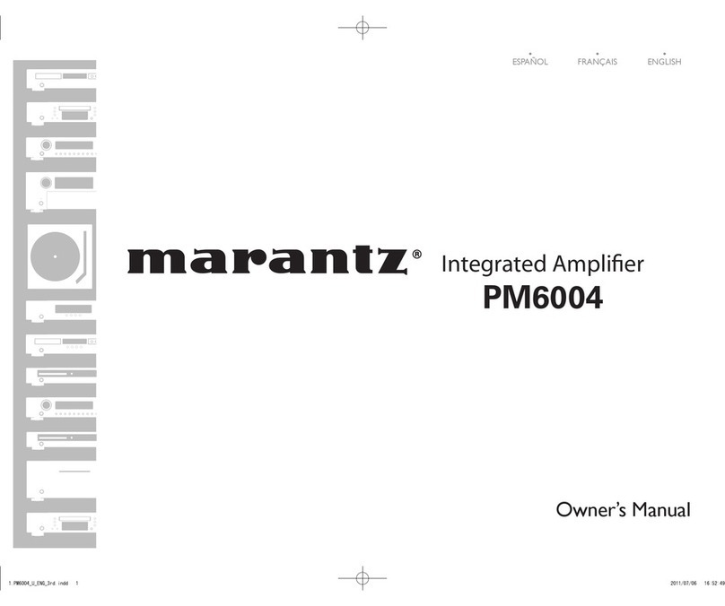
Marantz SC-8 User manual

Other Marantz Amplifier manuals
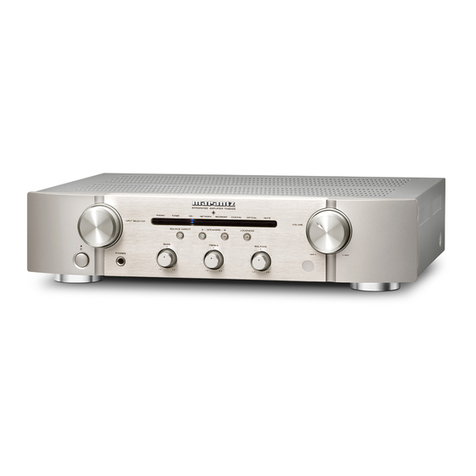
Marantz PM-14S1 User manual

Marantz

Marantz PM-14S1 User manual

Marantz PM551 User manual

Marantz

Marantz PM551 User manual

Marantz PM17A/F1N User manual

Marantz

Marantz PM17A/F1N User manual

Marantz PM-17SA/F1N User manual

Marantz

Marantz PM-17SA/F1N User manual

Marantz PM6003 User manual

Marantz

Marantz PM6003 User manual

Marantz PM8200 User manual

Marantz

Marantz PM8200 User manual

Marantz PM-17SA User manual

Marantz

Marantz PM-17SA User manual

Marantz PM7005 User manual

Marantz

Marantz PM7005 User manual

Marantz CD-400 User manual

Marantz

Marantz CD-400 User manual

Marantz PM-17mk II User manual

Marantz

Marantz PM-17mk II User manual

Marantz PM8003 Quick start guide

Marantz

Marantz PM8003 Quick start guide

Marantz RHA6 User manual

Marantz

Marantz RHA6 User manual

Marantz 541110491028M User manual

Marantz

Marantz 541110491028M User manual

Marantz 74 PM52/00B User manual

Marantz

Marantz 74 PM52/00B User manual

Marantz PM-15S1G User manual

Marantz

Marantz PM-15S1G User manual

Marantz PM-14S1 User manual

Marantz

Marantz PM-14S1 User manual
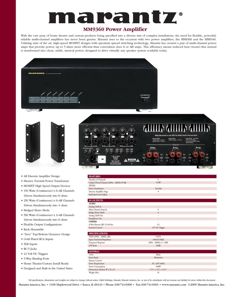
Marantz SM6100SA User manual

Marantz

Marantz SM6100SA User manual

Marantz PM-11S1 User manual

Marantz

Marantz PM-11S1 User manual

Marantz PM6005 User manual

Marantz

Marantz PM6005 User manual

Marantz PM6006 User manual

Marantz

Marantz PM6006 User manual

Marantz THX Ultra MA-6100 User manual

Marantz

Marantz THX Ultra MA-6100 User manual

Marantz PM7001 User manual

Marantz

Marantz PM7001 User manual

Marantz 1072 User manual

Marantz

Marantz 1072 User manual

Marantz SM17 F1N User manual

Marantz

Marantz SM17 F1N User manual

Popular Amplifier manuals by other brands

Magnat Audio EDITION FOUR Owner's manual/warranty document

Magnat Audio

Magnat Audio EDITION FOUR Owner's manual/warranty document

Inter-m PA-2000A Operation manual

Inter-m

Inter-m PA-2000A Operation manual

Yamaha TX6n owner's manual

Yamaha

Yamaha TX6n owner's manual

Peavey TNT 150 user guide

Peavey

Peavey TNT 150 user guide

Bosch LBB 1903/10 Installation and user instructions

Bosch

Bosch LBB 1903/10 Installation and user instructions

Avocent Emerge DA1200D Installer/user guide

Avocent

Avocent Emerge DA1200D Installer/user guide

Redgum RGi35 operating instructions

Redgum

Redgum RGi35 operating instructions

Cambridge Audio AXA25 user manual

Cambridge Audio

Cambridge Audio AXA25 user manual

Alpine MRP-M200 owner's manual

Alpine

Alpine MRP-M200 owner's manual

Technical Pro H1502UrBT user manual

Technical Pro

Technical Pro H1502UrBT user manual

FMS EMGZ307 operating manual

FMS

FMS EMGZ307 operating manual

Racal Instruments 5601 user manual

Racal Instruments

Racal Instruments 5601 user manual

Valcom V-1094A Technical specifications

Valcom

Valcom V-1094A Technical specifications

Cambridge Audio 851D user manual

Cambridge Audio

Cambridge Audio 851D user manual

QSC 3800 Specifications

QSC

QSC 3800 Specifications

NAD C300 owner's manual

NAD

NAD C300 owner's manual

Rotel RMB-1077 owner's manual

Rotel

Rotel RMB-1077 owner's manual

Peavey Monitor 300 Series operating guide

Peavey

Peavey Monitor 300 Series operating guide

manuals.online logo
manuals.online logoBrands
  • About & Mission
  • Contact us
  • Privacy Policy
  • Terms and Conditions

Copyright 2025 Manuals.Online. All Rights Reserved.

MARANTZ
DESIGN
AND
SERVICE
Using
superior
design
and
selected
high
grade
components,
MARANTZ
company
has
created
the
ultimate
in
stereo
sound.
Only
original
MARANTZ
parts
can
insure
that
your
MARANTZ
product
will
continue
to
perform
to
the
specifications
for
which
it
is
famous.
Parts
for
your
MARANTZ
equipment
are
generally
available
to
our
National
Marantz
Subsidiary
or
Agent.
ORDERING
PARTS:
Parts
can
be
ordered
either
by
mail
or
by
telex.
In
both
cases,
MARANTZ
part
number
has
to
be
specified.
If
you
order
by
mail,
fulfil
MAR
ANTZ
order
forms.
MARANTZ
S.A.
EUROPEAN
PARTS
DEPARTMENT
2,
Avenue
Léopold
ill
B-7120
PERONNES-lez-BINCHE
BELGIUM
TWX:
57589
SEPLT
B
The
following
information
must
be
supplied
to
eliminate
delays
in
processing
your
order:
Complete
address
Complete
part
numbers
and
quantities
required
Description
of
parts
Model
number
for
which
part
is
required
Way
of
shipment
Signature:
any
order
form
or
telex
must
be
signed
otherwise
such
part
order
will
be
considered
as
null
and
void.
OOS
Ne
PARTS
ORDERING:
Parts
may
be
ordered
from
the
following
addresses:
EUROPE
MARANTZ
S.A.
MARANTZ
NORSKE
A.S.
MARANTZ
DENMARK
MARANTZ
GMBH
AUSTRIA
European
Parts
Department
Refstadalleen
13
Bregnergdvej
132b
Wiedner
Hauptstrasse
98
2,
Avenue
Léopold
Il
Oslo
5
3460
Birkergd
1050
Wien
B-7120
Péronnes-lez-Binche
Norway
Denmark
Austria
Belgium
Telex:
19659
Telex:
39137
Telex:
113583
Telex:
57589
MARANTZ
S.A.
MARANTZ
FRANCE
MARANTZ
BELGIUM
MARANTZ
SVENSKA
A.B.
326
Avenue
Louise
Bte
32
4
Rue
Bernard
Palissy
45
Rue
Auguste
Van
Zande
Svartviksvangen
56
1050
Brussels
92600
Asniéres
1080
Brussels
Traneberg
-
Box
12016
Belgium
France
Belgium
16112
Bromma
Telex:
26602
Telex:
611651
Sweden
Telex:
13449
MARANTZ
GERMANY
GMBH
MARANTZ
AUDIO
U.K.
LTD.
Max
Planckstrasse,
22
Unit
15/16
6072
DREIEICH
1
Saxon
Way
Industrial
Estate
West
Germany
Moor
Lane
Telex:
4185316
Harmondsworth
UB7
OLW
Great
Britain
Telex:
935196
AUSTRALIA
MARANTZ
AUSTRALIA
PTY.,
LTD.
32
Cross
Street
Brookvale,
N.S.W.
2100
Australia
Telex:
24121
All
of
the
above
locations
are
fully
equipped
to
take
care
of
your
total
service
needs.
Because
various
countries
have
dé
ffering
configuration
requirements,
it
is
necessary
that
you
contact
the
service
facility
in
your
particular
country.
In
the
ev
nt
that
there
is
no
service
location
listed
for
your
country,
please,
contact
the
nearest
facility
for
the
necessary
assistance.
In
case
of
difficulties,
do
not
hesitate
to
contact
the
Technical
Department
at
abovementioned
address.
ERR
en
Been
ERE
ZZ’
TABLE
OF
CONTENTS
SECTION
PAGE
INTRODUG
TION:
ecco
oie
Sn
ia
Sees
RE
Ee
GR
AS
BAe
eg
Re
Sees
Be
RASS
1
1.
SHOCK,
FIRE
HAZARD
SERVICE
TEST
...........
ccc
eee
eee
eee
1
Ds
FEATURES
io
cs5
boob
bsiehek Saharan
BR
wba
whe
outs
Ga
sewed
ean
canes
(2a
aha
ge
wee
aw
he,
SIGE
Nees
A
ores
ats
1
3)
BAW:
BOARDS
e036
coe
fea
ke
hie
Saeed
Ate
baa
Rowenta
aad
Raean
Ch
Aa
ee
ere
2
4.
VOLTAGE
CONVERSION
.....
0.0...
ce
ee
ee
een
e
teen
tee
e
ee
ee
eas
2
5B.
(BLOCK:
(DIAGRAM
oiicek
ik
ieee
oe
Berea
Pee
eek
le
ete
ko
We
SE
Sore
WS
we
ae
3
6.
DIAGRAM
AND
COMPONENT
LOCATIONS
............
0.0.2.0.
cece
eee
eee een
nes
4
6.1.
MC
Phono
Assembly
(P400)
Schematic
Diagram
and
Component
Locations
...........--
000+
eee
eee
4
6.2
Balance
VR/Mode
Switch
Assembly
(PGOO)
Schematic
Diagram
and
Component
Locations
.............
4
6.3.
Power
Supply
Assembly
(P800)
Schematic
Diagram
and
Component
Locations
...............-022005
7
6.4
L.E.D.
Assembly
(PY00)
Schematic
Diagram
and
Component
Locations
...............00
ees
eee
eee
7
6.5
Input
Selector
Switch
Assembly
(PSO01)
Schematic
Diagram
and
Component
Locations
..............+.-:
8
6.6
Tone
Amp.
(L-Ch)
Assembly
(PEO1)
Schematic
Diagram
and
Component
Locations
...........-.+.005
8
6.7.
Loudness
Switch
&
Volume
Assembly
(PJ00)
Schematic
Diagram
and
Component
Locations
............
9
6.8
Headphone
Assembly
(PX00)
Schematic
Diagram
and
Component
Locations..............02
0000
eee
9
6.9
Tone
In/Out
Switch
Assembly
(PTOO)
Schematic
Diagram
and
Component
Locations
................-
9
6.10
Tone
Amp.
(R-Ch)
Assembly
(PE02)
Schematic
Diagram
and
Component
Locations
...............65.
9
7.
EXPLODED
VIEW
AND
PARTS
LIST
...........
0...
cece
eee
eee
eee
eee
eee
ne
10
8°
‘ELECTRICAL:
PARTS:
EIST:
scxc5
ike
aecttuctitsie
te
tik
oe
et
csi
Bees
ee
16
9.
TECHNICAL
SPECIFICATIONS
.......
0...
ccc
cc
cect
terre
eee
een
e
tne
tenes
ae
22
10.
SCHEMATIC
DIAGRAM
..............-.02000
6:
Fcc
aa
en
Mkt
Ub
cee
ras
Sa
Dace:
CANS
1S
Leelee
24
MARANTZ
MODEL
Sc-8
STEREO
CONSOLE
AMPLIFIER
INTRODUCTION
This
service
manual
was
prepared
for
use
by
Authorized
Warranty
Staions
and
contains
service
information
for
the
Marantz
Model
Sc-8
Stereo
Console
Amplifier.
Servicing
information
and
voltage
data
included
in
this
manual
are
intended
for
use
by
knowledgeable
and
ex-
perienced
personnel
only.
All
instructions
should
be
read
carefully.
No
attempt
should
be
made
to
proceed
without
a
good
understanding
of
circuitry
operation.
The
parts
list
furnishes
complete
ordering
information.
Most
replacement
parts
should
be
ordered
from
the
Marantz
Company.
However,
a
simple
description
is
included
for
parts
which
can
be
obtained
locally.
1.
SHOCK,
FIRE
HAZARD
SERVICE
TEST
CAUTION:
After
servicing
this
appliance
and
prior
to
returning
to
customer,
measure
the
resistance
between
either
primary
AC
cord
connector
pins
(with
unit
NOT
connected
to
AC
mains
and
its
Power
switch
ON),
and
the
face
or
front
Panel
of
product
and
controls
and
chassis
bottom.
Any
resistance
measurement
less
than
1
Megohms
should
Cause
unit
to
be
repaired
or
corrected
before
AC
power
is
applied,
and
verfied
before
return
to
user/customer.
Ref.
UL
Standard
No.
1270.
Para.
66.
3.
D
(Mandatory
Test
after
servicing
Electrical
Appliances,
effective
7-1-83).
2.
FEATURES
@
MC
Head
Amplifier
(13
transistors
for
each
channel)
The
MC
head
amplifier
uses
a
push-pull
amplifier
in
the
first
stage
which
consists
of
4
very
low
noise
NPN
tran-
sistors
and
4
very
low
noise
PNP
transistors.
It
uses
also
push-pull
transistors
in
the
second
stage
and
an
SEPP
circuit
in
the
output
stage.
The
feedback
circuit
impedance
is
reduced
és
much
as
possible
to
improve
the
S/N
ratio,
and
a
voltage
gain
of
26
dB
(20
times)
is
obtained
at
a
rated
input
level
of
110
uV.
@
PHONO
Amplifier
(11
transistors
for
each
chamel!)
The
PHONO
amplifier
uses
full
push-pull
citcuits
con-
sisting
of
11
transistors
for
each
channel,
sc
low
TIM
distortion
and
a
high
S/N
ratio
are
obtained.
The
first
stage
is
a
push-pull
circuit
consisting
of
very
low
noise,
high
Gm
N
channel
and
P
channel
FETs,
combined
with
a
cascode
current
Miller
circuit
so
that
degradation
of
characterisitics
of
following
crcuits
due
to
input
stage
impedance
fluctuations
is
prevented.
The
second
stage
consists
of
an
emitter
follower
buffer
amplifier
and
a
push-pull
voltage
amplifier.
The
output
stage
uses
an
SEPP
circuit
which
s
adequate
to
any
type
of
load.
The
equalizer
elements
have
very
low
impedance
compared
with
conventiona
equalizer
circuits,
so
a
S/N
ratio
of
90
dB
is
obtained
a
the
rated
input
level.
The
equalizer
elements
used
are
metal
filn
resistors
with
tolerance
of
1%
and
polypropylene
capei
tors
with
tolerances
of
2%,
so
RIAA
phono
equalizationaf
/0.2
dB
is
obtained
over
the
audio
range
from
20
Hz
to?O
kHz.
The
input
impedances
of
27
kQ,
47
kQ
and
00
kQQ
are
provided
to
allow
different
cartridges
to
be
connected
when
the
PHONO
1
input
is
selected.
The
output
stage
is
provided
with
a
relay
tc
snute
un-
desireable
noise
when
the
power
is
switched
ON
and
OFF,
and
with
an
EQ
subsonic
filter
to
reduce
turnta
#e
rumble
and
flutter
noise.
e@
TONE
Switch
The
TONE
switch
allows
the
number
of
coupling
capa-
citors
to
be
reduced
to
one
by
applying
the
PHONO
amplifier
output
signal
directly
to
the
line
amplifier
when
the
switch
is
set
to
the
TONE
OUT
position.
The
gain
and
input
sensitivity
are
not
changed
by
operating
this
switch.
TONE
OUT
HEADPHONE.
OUT
@
Line
Amplifier
The
line
amplifier
consists
of
15
transistors
for
each
channel,
and
uses
push-pull
circuits
which
operate
in
class
A
in
all
stages
to
reduce
TIM
distortion
and
im-
prove
the
S/N
ratio.
The
input
stage
uses
a
source
follower
with
dual
FETs
to
prevent
it
(the
input
stage)
from
affecting
following
stage
characteristics.
The
source
follower
output
signal
is
applied
to
the
differential
amplifier
through
dual
transistors.
One
of
the
differential
amplifier
output
signals
is
phase-
inverted,
then
both
output
signals
are
applied
to
the
second
stage
push-pull
amplifier
through
buffer
amplifiers.
The
power
amplifier
stage
uses
newly
developed,
super
high
f7
(200
—
250
MHz)
power
transistors
which
are
connected
in
a
Darlington
configuration.
This
power
amplifier
stage
operates
in
pure
class
A,
and
features
flat
frequency
response
and
low
TIM
distortion.
This
amplifier
can
drive
headphones
in
class
A
operation,
as
well
as
a
main
amplifier.
3.
P.W.
BOARDS
As
can
be
seen
from
the
circuit
diagram
the
chassis
of
Model
Sc-8
consists
of
the
following
units.
Each
unit
mounted
on
a
printed
circuit
board
is
descrided
within
the
square
enclosed
by
a
bold
dotted
line
on
the
circuit
diagram.
1.
MCPhono.........
mounted
on
P.W.
Board
P400
2.
Power
Supply
......
mounted
on
P.W.
Board
P800
3.
Tone
Amp.
(L-Ch)
...
mounted
on
P.W.
Board
PEO1
4.
Tone
Amp.
(R-Ch)
...
mounted
on
P.W.
Board
PEO2
5.
Balance
VR/i
Mode
Switch
..
....
mounted
on
P.W.
Board
PGOO
6.
Loudness
Switch
&
Volume
......+-55
mounted
on
P.W.
Board
PJOO
7.
Input
Selector
Switch
.
mounted
on
P.W.
Board
PS01
8.
Tone
In/Out
Switch
..
mounted
on
P.W.
Board
PTOO
9.
Headphone
........
mounted
on
P.W.
Board
PX00
10.
L.ED.
.
.......-
mounted
on
P.W.
Board
PY00O
4.
VOLTAGE
CONVERSION
@
EUROPEAN
MODEL
ONLY
CAUTION
To
convert
the
unit
to
a
different
power
source
voltage,
DISCONNECT
POWER
SUPPLY
CORD
FROM
AC
change
the
position
as
illustrated
in
the
drawing
below.
OUTLET
BEFORE
CONVERTING
VOLTAGE.
Voltage
Conversion
Chart
VOLTAGE
SELECTOR
Note
on
safety:
Symbo!
A\
Fire
or
electrical
shock
hazard.
Only
orignal
parts
should
be
used
to
replace
any
part
marked
with
symbol
A\
.
Any
other
component
substitution
(other
than
original
type),
may
increase
risk
of
fire
or
electrical
shock
hazard.
:
fe)
FLAT
AMP
MUTING
O
EQ
SUBSONIC
Hi
FILTER
PRE
OUT1
PHONO
2
:
IN
Q
PRE
OUT
2
HEAD
BALANCE
|
PHONES
INPUT
SELECTOR
TUNER
PHONO
TV/AUX
VOLUME
o
+8dB
OFF
+4dB
Y
LOUDNESS
STEREO
Zz
¥
O
©
REVERSE
©
oL+R
1
*L
i
SOURCE
oR
2
TAPE
MONITOR
1>2
SOURCE
2-1
TAPE
COPY
g
WVHYDVId
4901E
6.
DIAGRAM
AND
COMPONENT
LOCATIONS
6.1
MC
Phono
Assemiily
(P400)
Schematic
Diagram
and
Component
Locations
woso
Y
:
OS
A
I
eG
9.9200
0
ad
ed
aba
bd
Bo
vosv
—
APM43
47012)
2
RMO7
~
at
Caos:
RM25
+8)
85y
470
0.0022
68
ee
9.04
ARLE!
10
SUSY
4
PHONO
|
RUBS
ache
4
©
|
2108
Fo.or
Me
ES
oy
ie
Vv
47k
[S
RLOS
ERLO7
Neva
a
OL35
27k
100k
2.20 F228
2e4y
ne
Cf)
ores
ata
aR)
ae
plo]
”
“|
Ke
MC
PHONO
2
{)
23
S
clos
AL4I
RL57
100
PHONO
SELECTOR
100P
56
RL6I]
cuss
ciar
RM2I
470
ese
Fe
1
|
00/25
725v
(cMOI
220/6.3V
ov
RM23
FA
vw
M4
Laas
H
‘<
uN
Fe
19
<4
OM25
finn
4
70
"4
N
tp
GQ
e
4
N
bey
POL)
|
-asv
HAM
9
|
ass
aa
sese
|
a
ewe
9
)#
—
;
(8)
are
5
3
T
tO)
al
gle
A\RMaS
5
es
0.90
:
O
el
8
RMI3
io:
‘470
2W)
RL39
z
z
Oosieor
me
ies
2
cmos
RMo9
S20
|
cw
amar
ONT
she
ues
56k
a
nS:
aI
|
ote?)
puowo2jz]
$
0.0018:
Aporeh
46)
J
0.0022
2
a70/i6y|
4a
Bas
wens
7
RLS
RLe9,
867)
fe
4
100
O
iy’
RLS9
100
Py
i
2
Ree
nwo
[7
tag
cla
nd
&
“Se
©)
-
eT
$
M
47016)
022
s
33
-anT
aes
$401
es
8
Stools
bens
°
Armas
8
RL27
(P\oL27
0
loL37
s
90187)
aoe
|
”)
om20
3
S78
12M)
3
:
)
UN
a
Se
S|
g
~8.5v
S
sf
+
2
pried
QL
33
ie
21
(88)
weet
ov
©)
&)
ce
an
=
a
cuz
Rua
sek
“3
*
H
RM22
12
g
470/16)
93
cMoe
I
!
bid
220/6.3¥
470
(6)
wey
ia
Wy
+euis
HSV
oat
i
Reh
are
mos]
£20050.
Te
oF
220/35V
SOV
i
100
OF
000/35
‘
Si
roe
RUS
27k
CL45
i
PHONO
2
22x
=
eMos
[+
Rmzo
A5
RL6S
(6)
Y/
FE
4706)
fl
5
63
CLI3
Op
|
|
~0.6V
|
A
2
muses
2am
@
“le
:
:
Ks
&
{)
2
op
Leh
Mos
8.5v_QMO6
SQ
J
poled
Mio
JARMee
/
-
99
G14
wos
war?
47016)
Jo.oozz
6s
[so
caw)
4
;
Go2ed
eens
w——
[se
88)
7376
+
ia?
SLOl-3
Stoi-4
so,
Js:
sz
les
o
Rags
2.20
Tico
(96)
m5
78
OO—=50
tor
7)
79
ARLB2
10
onl:
:
ke
TIS,
usy
|
:
330
:
;
Hl
28.50
Rech
Ratt
RAIS,
R423
Raa3
R437
Te
QL06
waLos
RL26
PHONO)
id
ia
tgp
gel
te
ag
ew
ne
AMP
26.5V
P
Loe
B.g8
:
caor7_
27¥
17
av
4
s
—
pe
2408)
4
0.0022
9413
TAK
)
94
oe
set
ue
7
P 4 :
090—=0
®
:
A466
2
2
4
a)
&)
€Q)
oaes
ik,
os
7
Fs
ay
Pros
;
é
©
Ra01
30K(6)
caso)
cae?
RLS@
pig2
PE
g
4
ow-e
nae
:
>
o-W-2
e
raos]
(9
wa
eres,
2225v
°
56K
woo
Ae
clas
yi
a.
a
Do
®
i :
f
ye
F
.
7 <
kG)
040!
ae
P
©
io
rs
t
a
GES
|
3
(sew
1oo/2sv
sf
a
_|
“Pho,
B
a
oWi—e8:
E
mm
3
a
H—+f-0-6
O86
.
=
&
©
R403
0K
S
cas
10447
Rage
RAG?
!
OY)
48
+
1
a,
. s A
eatent
fe
a
2}
o»
[oS
tele
yf
E
T
|||
Q#
ott
~
4
RLSO
QLBAaLa2
I
R405
WOK(G)
=
T
cap
|
Raa
&
Ria
i
i
:
‘uf
°
z
e
id
Base
at
4
oe
0403
oss
ae
Sov
I
a
rico
(vem)
RL70
ware
r
“
Mr
:
id
cara
Fa
R453
1
100
100
:
ae
i
©
Ra02
39k
(6)
a
680p=—
22K)
%
'
O
*
&
cat
mn
H
RL
6
i
3
fond}
oo
es
€h)
ar
6.03316)
my
|
mse
110
r---4
L440
Reh
oF404
WoKs)
8
S
2418
ear
w|
SOV
‘
'
3
++
20
$
ea
A
Ras7/5
|
Fy
1
—_
‘
3
ot
R404
160K1G)
|
©
gai
|
8
3
0425
'°)
side
I
g
4
QL
38
:
t
re
Quis
sie
é
Ra35
Ra39
Reo
Te
|
g
\
zZ
raixs
Lo
Raia
IRazs
275
82
<
Aras
|
OL
34]
9
5
a
—_
3
Lo
«eS
bax
130
130.
L
o
82
(1/2W)
|
as]
nL 24
104
Zz
‘
a
]
g
cao
+
+
bry
=
:
es
100p
He
ASS
PAS
—
8)
H
F
cL20
“a
SV
47
:
8
Cc
2
=)
Sov
220/38¥
i
z
ot
@
C436
t
? ‘
$
asl?
|
ne
are
U9
5.9.
QL09
88)
aaa
;
an
Ws
®
E
150
R470
einen
|
CLI4
10p
1
J
4
aes
5
Perr
!
yc
LI3
Ra58.
rot
i]
ge
eS
Se
ea
a
ee
7
828
sw
REST!
ee
CT
Pe
z
“e
5
(0420
[sues
:
zeo/s0v
|
|
i
8,
&
We
T
caez
$
|
1
<
|
I
eur)
oe
|
a
'
esen
I
t
60
(31),
=
ser
i
1
ae
Yl
[se
fi395
!
aul
He
4
ir
Pine
'
a6
t
é
’
5
a
38
[
[ee
aa
ROT
Fa
8
lek
;
"Ssle|
'
Qo oO
9
oO
S2_(/)
ate
:
%
a2
78
be
q
H
[risa
RLS
SRL92
§1
33
5
oh
:
nS
‘
BL2I
4
:
zrtzs
LLO
OS
RLSI
470Ky
22k
seakdnat
teal
dy
Rg
AS,
ae
ae
|
Lr}
‘eee
"9
eye
‘k
OL4s
S/Slolg
NOt
Poe
nar
ess
‘y
Q
:
42%
44
52
56
©
Bh
bas
iad
bol
SLOI-2
a
Ea
>
ere
i
ee
Wivamrege
ae
7
.
“@®
CB
as
O—vi-ose
errr)
:
t
)
oo
ee
ASRLBI
10
SUSv
OL3I
OL35;
arr
Vv
ig
RLS7
100
ALE!
10
(v2
ov
N07
25v
ctor
_e
Hl
3
e
:
oa
,
;
.
ds
‘
i
cate
' :
e
a
: ;
i
\
‘¢
: ‘
ie
mec
i
i :
mk
C)
nS
me
wy
a
LG
~~
@e)x
fz
°
i
lav37
o
2
:
ans
Sa
u
oc
°
2.
2k
KC)
Ct
:
§
4
Me
:
‘©
&
—29.5V
a
ae
F
7
OL
33
i L
3
LOLi7
rust
L
RL3S
“3
j
;
ae)
o
om
er
2.2k
330
RLes
oA
[ie
!
;
cea
oe
+CLI9
=SSV
OG
—
738)
35V
{
"
4
22073!
a
220/
t
+
Laed
=
oe
se
$+
CL4E
Pere
27k
eS?
RLS
cut
»
CLA2
ALES
7
:
AoE
eR
ee
Aa!
eg
S
Ld
"
e.
e
op
o
a
/
Fa
SLOI-3
ARL82
10
FSV
J
pe
RL34
EPS
iy
2850
)
.
pias
)
WS
B
ue
oY
oL26
eL22
meee
if
R58
RL62
2070
5.6x
og
CLoeyRi3e
ew
100°
|
sé
4
Ht
(Pr
18
av
QL30
()
a
RLaO
ol
3
’
r1
RL64
2
Zi
10
aI
aL24
Rigo
(vam
o
100
|
[al
@
Qc
)au'e
Ruso
yee
E
28
“28.5V
8
QL28
a
28
z
ase
SY
283v
a
ne
Baan
SNe
aL34
2
RL84
OA
2
cuze
ob
cL20
“tb
aha:
220/35
+
220/35V
RL76
27k
V-
CLI4
10p
6.3
Power
Supply
Assembly
(P800)
Schematic
Diagram
and
Component
Locations
6.5
Input
Selector
Switch
Assembly
(PS01)
Schematic
Diagram
and
Component
Locations
6.7
——o
—
Qua
Pies
3?
~
Piae
16
ty)
15.412)
PSOO
4)
Rows
:
5
>
TUNER
oe
rT
PHONO
|
Su0rm1
mot!
Ace
eS
ee
|
=
9006
=
TV/AUX
soi
=
a
a
eg
OFO
o
a
A
o3
TT
ton
CB15-VC818
(UNIONLY
Rau
Oo
805
5.6
uw)
OBIT
m
bald
H6
°
a
T
a
hk
sso2
e
“s
A
Oo
7
2]
3
el
a
oa
ee oo
Cle
me)
=
28
33
Sst)
)
ee]
oe
So,
a
38]
3s
ra
oe
=
se
ey
Re19
Oo
Leh
_
‘S6i
oe
FO
=
8
|8
2
reir
4803
Lsvornm2
A;
al
|*
i
OFr©
a
|
PJOO
\
|COO3
oa
re)
oo
J
=~
ea
|
3
us
3}
=
Oo
Rech
4
23]
28
Om
|
88]
ee
°
ee
a
35]
8&8
ea
NO]
©>O
ReIB
820}
F
iw2
SSTPFl,
Sex
rhs
5
O
ROIS
_
ams
|
8
o
Reh
“OFF
g
ail
813
°
°
fa
RSO!
560
9.
ry
2-1
184%
AlA
Wass
220
oO
ee
2
ee
oF
oiset
wz
L___t
O
[J
a
C6}
I0
23.54,
O
50
BSH
i
'
re)
6,4,
16
:
7
©
Rso2
560
es
O-—-O—-W
i
Reh
F801!
3802
6.6
Tone
Amp.
(L-Ch)
Assembly
(PEO1)
Schematic
Diagram
and
Component
Locations
6.10
a
“ge
#4,
fo
TREBLE
Oolress
PEOO
t.]
RE49
470
wwew
PEOO(L)ch
cee
\/50y
+
33C
6.4
L.E.D.
Assembly
(PY00)
Schematic
Diagram
and
Component
Locations
|
PYOO
|
(AN
STINIGOD
}
4
AN
Oro
atAW
lREo2
220k
a!
RES3
S0x(8)
RE37
82k
®
ey
“a
=
_
boo
REG:
390
REA3
a7K
AW
ce25
ce27
0.039
0.0047
z
a)
os
sly
a
a
JEo2
i
oe
ee
rc
)
{
RESS
20K(W)
|
6.5
Input
Selector
Switch
Assembly
(PS01)
Schematic
Diagram
and
Component
Locations
6.7
Loudness
Switch
&
Volume
Assembly
(PJ00)
6.8
Headphone
Assembly
(PX00)
fe
a
os
—
=
Schematic
Diagram
and
Component
Locations
Schematic
Diagram
and
Component
Locations
ey)
1812)
[F500
al
:
ae
3
I]
in
on
tea
'
|
syn
orto,
a
JXOL
Pin
|
sso
|
PXOO
Waso6
220
RS04
220
6.9
Tone
In/Out
Switch
Assembly
(PTO0)
Schematic
Diagram
and
Component
Locations
6.6
Tone
Amp.
(L-Ch)
Assembly
(PE01)
Schematic
Diagram
and
C
6.10
Tone
Amp.
(R-Ch)
Assembly
(PEO2)
Schematic
Diagram
and
Component
Locations
Bi
see
:
|
PEOO
(R}ch
and
O
t.[RE49
470
aw
oFcez
(007
5
100/35
ceoe
‘soy
REO4|
3.
me
100/35¥
Vv
E30
|
RES2
470(72W)
ces2
Wworsy
IREOa|
220K
KUTA
qyanee
RERO
RES3
SOK(8)
8.2K
RE37
82k
1-¥be
JEO?
rm
onto?
RESE
20k
(Ww)
bocce
oOo
JEI2
JEIO