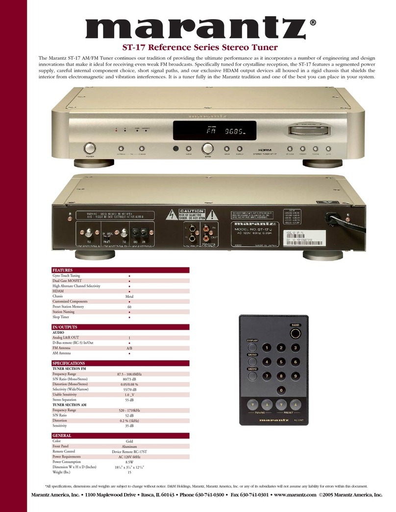
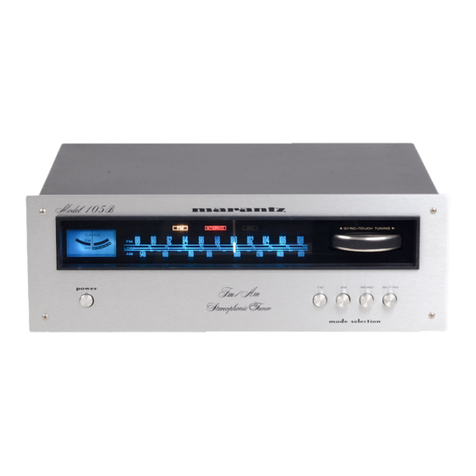
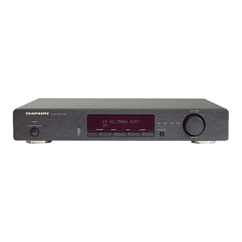
Marantz ST-17 User manual

13
ENGLISHFRANÇAISDEUTSCH
NEDERLANDS
ESPAÑOLITALIANO
PORTUGUÊS
SVENSKADANSK
R
Model ST-17 User Guide
Stereo Tuner

1
ENGLISH FRANÇAIS DEUTSCH
NEDERLANDS
ESPAÑOL ITALIANO
PORTUGUÊS
SVENSKA DANSK
iENGLISHi
WARRANTY
For warranty information, contact your local Marantz distributor.
RETAIN YOUR PURCHASE RECEIPT
Your purchase receipt is your permanent record of a valuable purchase. It
should be kept in a safe place to be referred to as necessary for insurance
purposes or when corresponding with Marantz.
IMPORTANT
When seeking warranty service, it is the responsibility of the consumer to
establish proof and date of purchase. Your purchase receipt or invoice is
adequate for such proof.
FOR U.K. ONLY
This undertaking is in addition to a consumer's statutory rights and does not
affect those rights in any way.
iFRANÇAISi
GARANTIE
Pour des informations sur la garantie, contacter le distributeur local Marantz.
CONSERVER L'ATTESTATION D'ACHAT
L'attestation d'achat est la preuve permanente d'un achat de valeur. La
conserver en lieu sur pour s'y reporter aux fins d'obtention d'une couverture
d'assurance ou dans le cadre de correspondances avec Marantz.
IMPORTANT
Pour l'obtention d'un service couvert par la garantie, il incombe au client
d'établir la preuve de l'achat et d'en corroborer la date. Le reçu ou la facture
constituent des preuves suffisantes.
iDEUTSCHi
GARANTIE
Bei Garantiefragen wenden Sie sich bitte an Ihren Marantz-Händler.
HEBEN SIE IHRE QUITTING GUT AUF
Die Quittung dient Ihnen als bleibende Unterlage für Ihren wertvollen Einkauf
Das Aufbewahren der Quittung ist wichtig, da die darin enthaltenen Angaben
für Versicherungswecke oder bei Korrespondenz mit Marantz angeführt werden
müssen.
WICHTIG!
Bei Garantiefragen muß der Kunde eine Kaufunterlage mit Kaufdatum vorlegen.
Ihren Quittung oder Rechnung ist als Unterlage ausreichend.
iNEDERLANDSi
GARANTIE
Voor inlichtingen omtrent garantie dient u zich tot uw plaatselijke Marantz.
UW KWITANTIE, KASSABON E.D. BEWAREN
Uw kwitantie, kassabon e.d. vormen uw bewijs van aankoop van een waardevol
artikel en dienen op een veilige plaats bewaard te worden voor evt, verwijzing
bijv, in verbend met verzekering of bij correspondentie met Marantz.
BELANGRIJK
Bij een evt, beroep op de garantie is het de verantwoordelijkheid van de
consument een gedateerd bewijs van aankoop te tonen. Uw kassabon of
factuurzijn voldoende bewijs.
iESPAÑOLi
GARANTIA
Para obtener información acerca de la garantia póngase en contacto con su
distribuidor Marantz.
GUARDE SU RECIBO DE COMPRA
Su recibo de compra es su prueba permanente de haber adquirido un aparato
de valor, Este recibo deberá guardarlo en un lugar seguro y utilizarlo como
referencia cuando tenga que hacer uso del seguro o se ponga en contacto con
Marantz.
IMPORTANTE
Cuando solicite el servicio otorgado por la garantia el usuario tiene la
responsabilidad de demonstrar cuándo efectuó la compra. En este caso, su
recibo de compra será la prueba apropiada.
iITALIANOi
Condizioni di garanzia
L'apparecchio e' garantito per 365 giorni dalla data di acquisto comprovata da
un documento attestante il nominativo del rivenditore e la data di vendita. La
garanzia sara' prestata con la sostituzione o riparazione gratuita delle parti
difettose.
Non sono coperti da garanzia difetti derivanti da uso improprio, errata
installazione, manutenzione effettuata da personale non autorizzato o,
comunque, da circostanze che non possano riferirsi a difetti di tunzionamento
dell'apparecchio. Sono inoltre esclusi dalla garanzia gli interventi inerenti
l'installazione e l'allacciamento agli impianti di alimentazione.
Gli apparecchi verranno riparati presso i nostri Centri di Assistenza. Le spese
ed i rischi di trasporto sono a carico del cliente.
La casa costruttrice declina ogni responsabilita' per danni diretti o indiretti
provocati dalla inosservanza delle prescrizioni di installazione, uso e
manutenzione dettagliate nel presente manuale.
Per informazioni sull'abbonamento al Servizio Assistenza postgaranzia e per
conoscere l'indirizzo dei Centri Assistenza Marantz rivolgetevi al nostro servizio
consumatori (telefono 1678-20026 - numero verde).
iPORTUGUÊSi
GARANTIA
Para informações sobre a garantia, contactar o distribuidor Marantz local.
GUARDAR O RECIBO DE COMPRA
O recibo é o registo permanente da compra que fez. Deve ser guardado num
local seguro, para ser apresentado em questões relacionadas com o seguro
ou para quando tiver de contactar a Marantz.
IMPORTANTE
Quando procurar assisténcia técnica ao abrigo da garantia, é da
responsabilidade do consumidor estabelecer a prova e data de compra. O
recibe é prova adequada.
iSVENSKAi
GARANTI
För information om garantin, kontakta Marantz lokalagent.
SPAR KVITTOT
Kvittot är ett inköpsbevis på en värdefull vara. Det skall förvaras säkert och
hänvisas till vid försäkringsfall eller vidkorrespondens mod Marantz.
VIKTIGT
Fö att garantin skall gälla är det kundens sak att framställa bevis och datum om
köpet. Kvitto eller faktura är tillräokligt bevis fö detta.
iDANSKi
GARANTI
Henvend dem til Deres MARANTZ-forhandler angående inrformation om
garantien.
GEM DERES KVITTERING
Deres købskvittering er Deres varige bevis på et dyrt køb. Den bør gemmes
godt og anvendes som bevis, hvis De vil tegne en forsikring, eller hvis De
kommunikerer med Marantz.
VIGTIGT
Det påhviler forbrugeren at skaffe bevis for købet og købsdatoen, hvis han eller
hun ønsker garantiservice. Deres købskvittering eller faktura er et fuldgyldigt
bevis herpå.

1
ENGLISHFRANÇAISDEUTSCH
NEDERLANDS
ESPAÑOLITALIANO
PORTUGUÊS
SVENSKADANSK
CONTENTS LIST
English............................................................................................................................................................................................... page 2
Français............................................................................................................................................................................................. page 7
Deutsch............................................................................................................................................................................................ Seite 12
Nederlands ................................................................................................................................................................................... pagina 17
Español......................................................................................................................................................................................... pagina 22
Italiano........................................................................................................................................................................................... pagina 27
Português...................................................................................................................................................................................... página 32
Svenska........................................................................................................................................................................................... sidan 37
Dansk............................................................................................................................................................................................... page 42
Specifications .................................................................................................................................................................................. page 47
Figures............................................................................................................................................................................................. page 48
CE MARKING
English
The ST-17 is in conformity with the EMC directive and low-voltage directive.
Français
Le ST-17 est conforme à la directive EMC et à la directive sur les basses tensions.
Deutsch
Das Modell
ST
-17 entspricht den EMC-Richtlinien und den Richtlinien für Niederspannungsgeräte.
Nederlands
De ST-17 voldoet aan de EMC eisen en de vereisten voor laag-voltage.
Español
El ST-17 está de acuerdo con las normas EMC y las relacionadas con baja tensión.
Italiano
Il ST-17 è conforme alle direttive CEE ed a quelle per i bassi voltaggi.
Português
O ST-17 conforma com as diretrizes EMC e de baixa voltagem.
Svenska
ST-17 är tillverkad i enlighet med EMC direktiven och direktiven för lågvoltsutrusning.
Dansk
Model ST-17 er i overensstemmelse med EMC-direktiveet og direktivet om lavspænding.
English
To ventilate the unit, do not install the unit in a rack or bookshelf,
and note the followings.
- Do not insert objects beneath the unit.
- Do not block the ventilation slots at the top of the unit.
Do not place anything about 1 meter above the top panel.
- Make a space of about 0.2 meter around the unit.
Français
Pour que l'appareil puisse être correctement ventilé, ne pas
l'installer dans un meuble ou une bibliothèque et respecter ce qui
suit.
- Ne placer aucun objet sous l'appareil.
- Ne pas obstruer les ouães de ventilation du panneau supérieur.
Ne placer aucun objet à moins d'un mètre environ du panneau
supérieur.
- Veiller à ce qu'aucun objet ne soit à moins de 0.2 mètre des
côtés de l'appareil.
Deutsch
Um eine einwandfreie Belüftung des Geräts zu gewährleisten, darf
das Gerät nicht in einem Gestell oder Bücherregal aufgestellt
werden; die folgenden Punkte sind besonders zu beachten:
- Keine Gegenstände in das Gerät einführen.
- Die Belüftungsschlitze an der Oberseite des Geräts dürfen nicht
blockiert werden. Darauf achten, daß über dem Gerät ein
Freiraum von mindestens 1 meter vorhanden ist.
- Auf allen Geräteseiten muß ein Zwischenraum von ungefähr 0.2
meter vorhanden sein.
Nederlands
Installeer het toestel niet in een rek of boekenkast waar de ventilatie
mogelijk wordt gehinderd. Let tevens op de volgende punten:
- Plaats geen onderwerpen onder het toestel.
- Blokkeer de ventilatie-openingen aan de bovenkant van het
toestel niet. Zorg dat er tenminste 1 meter vrije ruimte boven het
toestel is.
- Zorg dat er 0.2 meter vrije ruimte rond het toestel is.
Español
Para ventilar la unidad no la instale en una estantería ni estante
para libros, y tenga en cuenta lo siguiente:
- No ponga objetos debajo de la unidad.
- No tape las ranuras de ventilación de la parte superior de la
unidad. No ponga nada a menos de 1 metro por encima del
panel superior.
- Deje un espacio de unos 0.2 metro alrededor de la unidad.
Italiano
Perch é l'unità possa essere sempre ben ventilata, non installarla in
scaffali o librerie e tenere presente quanto segue.
- Non inserire oggetti al di sotto dell'unità.
- Non bloccare le fessure di ventilazione sopra l'unità.
Non posare nulla per circa un metro sopra il pannello superiore.
- Lasciare 0.2 metro liberi tutto intorno l'unità.
Português
Para ventilar o aparelho, não instalá-lo dentro duma estante ou
algo similar, e observar as seguintes recomendações:
- Não insertar objectos debaixo do aparelho.
- Não bloquear as aberturas de ventilação na parte de cima do
aparelho. Deixar um espaço completamente livre de cerca de 1
metro acima do painel superior.
- Deixar um espaço de cerca de 0.2 metro ao redor do aparelho.
Svenska
För att ventilera enheten, ställ den inte i ett ställ eller bokhylla och
tänk på följande.
- Stick inte in föremål under enheten.
- Blockera inte ventialtionshålen ovanpå enheten.
Placera inte någonting närmare än 1 meter ovanför apparaten
eller enheten.
- Se till att det finns omkring 0.2 meter fri plats runt omkring
enheten.
Dansk
Anbring ikke apparatet i et rack eller en boghylde, da dette kan
bloke luftcirkulationen omkring apparatet. Iagttag ligeledes
følgende:
- Stik ikke genstande ind under apparatet.
- Bloker ikke ventilationsåbningerne ovenpå apparatet.
Anbring ikke noget nærmere end 1 m over apparatets overside,
- Sørg for, at der er et frit område på omkring 0,2 m omkring
apparatet.
ITARIANO
SI DICHIARA CHE L'APPARECCHIO SINTONIZZATORE ST-17 RISPONDE ALLE PRESCRIZIONI DELL'ART.
2, COMMA 1 DEL D.M. 28 AGOSTO 1995. N. 548
FOTTO A EINDHOVEN IL 01/09/1996.
“Este aparato lleva elementos antiparasitarios necesarios para cumplir con los limites que se
estableceran en el Anexo V del Reglamento sobre Pertubaciones Radioelectricas e Interferencias
aprobado en el Real Decreto 138/1989. (B.O.E de 9 de Febrero 1989).”
MARANTZ EUROPE B.V.
5600 JB EINDHOVEN
THE NETHERLANDS

3
ENGLISH FRANÇAIS DEUTSCH
NEDERLANDS
ESPAÑOL ITALIANO
PORTUGUÊS
SVENSKA DANSK
iENGLISHi
WARRANTY
For warranty information, contact your local Marantz distributor.
RETAIN YOUR PURCHASE RECEIPT
Your purchase receipt is your permanent record of a valuable purchase. It
should be kept in a safe place to be referred to as necessary for insurance
purposes or when corresponding with Marantz.
IMPORTANT
When seeking warranty service, it is the responsibility of the consumer to
establish proof and date of purchase. Your purchase receipt or invoice is
adequate for such proof.
FOR U.K. ONLY
This undertaking is in addition to a consumer's statutory rights and does not
affect those rights in any way.
NOTE:
This equipment has been tested and found to comply with the limits for a Class
B digital divice, pursuant to Part 15 of the FCC Rules. These limits are designed
to provide resonable protection against harmful interference in a residential
installation. This equipment generates, uses and can radiate radio frequency
energy and, if not installed and used in accordance with the instructions, may
cause harmful interference to radio communications. However, there is no
guarantes that interference will not occur in a particular installation. If this
equipment does cause harmful interference to radio or television reception,
which can be determined by turning the equipment off and on, the user is
encouraged to try to correct the interference by one or more of the following
measures:
— Reorient or relocate the receiving antenna.
— Increase the separation between the equipment and receiver.
— Connect the equipment into an outlet on a circuit different from that to which
the receiver is connected.
—Consulut the dealer or an experienced radio/TV technician for help.

1
FRANÇAISDEUTSCH
NEDERLANDS
ESPAÑOLITALIANO
PORTUGUÊS
SVENSKADANSK ENGLISH
PRECAUTIONS
The following precautions should be taken when operating the
equipment.
GENERAL PRECAUTIONS
When installing the equipment ensure that:
— the ventilation holes are not covered;
— air is allowed to circulate freely around the equipment;
— it is on a vibration free-surface;
— it will not be exposed to interference from an external source;
— it will not be exposed to excessive heat, cold, moisture or dust;
— it will not be exposed to direct sunlight;
— it will not be exposed to electrostatic discharges;
In addition, never place hevey objects on the equipment.
If a foreign body or water does enter the equipment, contact your
nearest dealer of service center.
Do not pull out the plug by pulling on the mains lead, hold the plug.
It is advisable when leaving the house, or during a thunderstorm, to
disconnect the equipment from the mains supply.
EQUIPMENT REAR PANEL
CONNECTIONS AND CONTROLS
(Figure 1)
ABC ANTENNA CONNECTIONS
Both FM and AM antenna can be connected to the tuner's terminals.
AFM ANTENNA A TERMINAL
The FM ANTENNA terminal is used to connect an external FM
antenna with a circular plug. It can also be used to connect the
accessory FM feeder antenna.
BFM ANTENNA B TERMINAL
The FM ANTENNA terminal is used to connect an external FM
antenna with a circular plug, or for connecting a cable network to the
tuner.
CAM ANTENNA TERMINAL
The AM terminal and the GND terminal are used to connect the high-
performance, low-impedance, AM loop antenna that is provided with
the receiver. The AM loop antenna can be used on top of the tuner or
can be mounted on a suitable rack or shelf near the tuner.
Interference may be reduced if the tuner is earthed.
In areas where the AM loop antenna supplied gives unsatisfactory
result, it is recommended that the tuner be connected to an outdoor
antenna. Use the terminal marked AM for this. Anearthing lead can
be connected to the terminal marked GND to further reduce
interference.
DFM ATTENUATE SWITCH (FM ATT.)
This switch attenuates the FM signal input to the ATTENNA B
terminal.
DX : For use when the FM signal is comparatively weak.
(The input FM signal is not attenuated.)
LOCAL: For use when the FM signal is comparatively strong.
(The input FM signal is attenuated by approx. 20dB.)
EOUTPUT JACKS
With the lead supplied, connect the output jacks to the tuner inputs of
your amplifier.
FREMOTE CONTROL BUS TERMINALS
Another item of audio equipment with a remove control bus terminal
can be connected to these terminals by using a specialpurpose
cable. The bus OUT terminal is used to send signals to another item
of equipment. The bus IN terminal is used to receive signals from
another item of equipment.
FOREWORD
This section must be read before any connection is made to the
mains supply.
EQUIPMENT MAINS WORKING SETTING
Your Marantz product has been prepared to comply with the
household power and safety requirements that exist in your area.
On the rear panel of the “K” Version product, a voltage selector (2-
position) is provided. Be sure to set the voltage selector to the mains
voltage of your area before using the unit.
When it is required to switch the predetermined voltage of your unit,
please consult your dealer or the service station in your area.
IMPORTANT:
This apparatus is fitted with an approved moulded 13 Amp plug.
To change a fuse in this type of plug proceed as follows:
1. Remove fuse cover and fuse.
2.Fix new fuse which should be a BS1362 5A, A.S.T.A. or BSI
approved type.
3. Refit the fuse cover.
If the fitted plug is not suitable for your socket outlets, it should be cut
off and an apprppriate plug fitted in its place.
If the mains plug contains a fuse, this should have a value of 5A. If a
plug without a fuse is used, the fuse at the distribution board should
not be greater than 5A.
NOTE:
The severed plug must be destroyed to avoid a possible shock hazard
should it be inserted into a 13A socket elsewhere.
HOW TO CONNECT A PLUG
The wires in the mains lead are coloured in accordance with the following
code:
BLUE-“NEUTRAL” (“N”)
BROWN-“LIVE” (L”)
1. The BLUE wire must be connected to the terminal which is marked
with the letter “N” or coloured BLACK.
2.The BROWN wire must be connected to the terminal which is
marked with the letter “L” or coloured RED.
3. Do not connect either wires to the earth terminal in the plug which
is marked by the letter “E” or by the safety earth symbol or
coloured green or green-and-yellow.
Before replacing the plug cover, make certain that the cord grip is
clamped over the sheath of the lead - not simply over the two wires.
COPYRIGHT
Recording and playback of any material may require consent. For
further information refer to the following:
— Copyright Act 1956
— Dramatic and Musical Performers Act 1958
— Performers Protection Acts 1963 and 1972
—any subsequent statutory enactments and orders
ABOUT THIS USER GUIDE
Refer to the Figure on the paged at the rear of this guid. The callout
numbers on the Figure correspond to those found in the text. All
references to the connections and controls that are printed in BOLD
type are as they appear on the unit.
WARNINGS
Do not expose the equipment to rain or moisture.
Do not remove the cover from the equipment.
Do not push anything inside the equipment through the
ventilation holes.
Do not handle the mains lead with wet hands.
2
ENGLISH FRANÇAIS DEUTSCH
NEDERLANDS
ESPAÑOL ITALIANO
PORTUGUÊS
SVENSKA DANSK
iDISPLAY BUTTON
When this button is pressed while a station name is being displayed,
the display is switched to the frequency display.
Pressing the button again returns to the station name display; if no
station name has been stored for the station being received. “NO
NAME” is displayed when the button is pressed.
oST-NAME BUTTON
Press before manual input of station name.
For details, refer to “NANUAL INPUT OF STATION NAMES”.
!0 PRESET BUTTON
For switching the GYRO CONTROL ring to the preset mode.
!1 TUNING BUTTON
For switching the GYRO CONTROL ring to the tuning mode.
!2 AUTO BUTTON
For switching the GYRO CONTROL ring to the auto tuning mode.
!3 GYRO CONTROL RING
Used for dialing control of tuning up/down, preset up/down, station
name character display and PTY selection.
!4 DISPLAY
åMEMORY – This indicator lights up for about 5 seconds after the
MEMO button has been pressed.
∫PRESET – This indicator lights up when the PRESET button is
pressed.
çSTEREO – This indicator lights up when an FM stereo broadcast
is being received.
∂AUTO TUNING – This indicator lights up when the AUTO TUNING
mode.
éTUNING – This indicator lights up when the MANUAL TUNING
mode.
ƒTUNED – This indicator lights up when a station is tuned.
©FREQUENCY/STATION NAME – This indicator shows frequencies
in MHz (FM) or kHz (MW, LW), (RDS) station name, radio text or
names you have assigned.
˙MONO – This indicator lights up in the MONO mode, which is
initiated when the MONO button is pressed.
GAC POWER CONNECTION
The correct voltage for operating your tuner is indicated on the rear
panel. Be sure the POWER switch is off before plugging the AC
mains lead into an electrical outlet.
HSCAN-STEP SELECTION
Changes the step when the tuner searches for the next station up or
down the scale. In Europe this swich should be set to 9 kHz steps in
AM.
CAUTION
THE UNIT MUST BE TURNED OFF BEFORE CHANGING
THE SCAN-STEP SELECTOR SWITCH POSITION.
WHEN THIS SWITCH IS SET TO OFF, THE CONTENTS OF
THE PRESET MEMORY AND STATION NAME ARE
ERASED AT THAT TIME, STORE THE CONTENTS AGAIN.
IFM DE-EMPHASIS SWITCH
This models are equipped with switchable de-emphasis.
The de-emphasis switch works in conjuction with this scan-step
selector switch.
The de-emphasis set to 50˚s when delivered from the factory.
EQUIPMENT FRONT PANEL
CONNECTIONS AND CONTROLS
(Figure 2)
qPOWER SWITCH
Press to switch the power ON. Press again to switch to power OFF.
The mains switch is secondary connected and does not disconnect
the entire set from the mains.
wANTENNA BUTTON
This button is only operable when the FM band is selected.
This button selects FM ANTENNA A and FM ANTENNA B.
The selected side’s LED will light.
eIF BAND BUTTON
This button is only operable when the FM band is selected.
This button selects the IF band’s WIDE or NARROW setting.
The selected side’s LED will light.
WIDE: High quality audio can be listened to.
NARROW: Ability to select neighboring stations is improved.
rIR SENSOR
Receives the infrared remote control signal.
tMONO BUTTON
Press to switch the receiving mode between the auto stereo mode
and more mode.
When the button is pressed into the in position, the receiving mode
becomes the mono mode.
When the button is pressed again, the receiving mode becomes the
auto stereo mode.
yBAND BUTTON
Use this button to select FM or AM (MW/LW) wave bands.
uMEMO BUTTON
Press to preset a receiving frequency in the memory. The MEMORY
indicator lights up for about 5 seconds when this button is pressed. It
is only during this period that a frequency can be preset in the
memory.

3
ENGLISHFRANÇAISDEUTSCH
NEDERLANDS
ESPAÑOLITALIANO
PORTUGUÊS
SVENSKADANSK
HOW TO PRESET A FREQUENCY IN THE MEMORY
1. Select FM or AM with the BAND button.
2. Select the desired station with the GYRO CONTROL ring.
3. Press the MEMO button.
“MEMORY” will flash on the display.
4. While the “MEMORY” indicator is flashing (approx. 5 sec.), turn the
GYRO CONTROL ring to the left or right to select the desired
preset number.
5. Press the MEMO button again.
The “MEMORY” indicator will go out, and memorization will be
finished.
CALLING UP STORED STATIONS
1. Confirm that the “PRESET” indicator is lit on the display. If not lit,
press the PRESET button to turn it on.
2. Turn the GYRO CONTROL ring to select the desired preset station.
DELETING THE CONTENTS OF THE PRESET MEMORY
1. Select the preset station you wish to delete.
2. Press the MEMO button.
The “MEMORY” indicator will flash on the display.
3. While the “MEMORY” indicator is flashing (approx. 5 sec.), turn the
GYRO CONTROL ring to set the preset number to “00”.
4. Press the MEMO button again.
The preset number and the “CLEAR” indicator will flash for approx.
2 seconds on the display and the memory will be deleted.
Station names memorized for the preset station will also be deleted
at the same time.
<GYRO RING operation method>
When the GYRO ring is turned to the right, the frequency or preset
number will increase, and when turned to the left, they will decrease.
STEREO TUNER ST-17
A B
WIDE NARROW
BAND MEMO
MONOIF BANDFM
ANTENNA
POWER DISPLAY ST NAME PRESET TUNING AUTO
MEMORY
4
1
2, 4
3, 5
OPERATION ON THE MAIN UNIT
SWITCHING ON AND OFF
When you want to switch you tuner on, press the POWER button.
When you wish to switch the unit off, simply press the POWER
button again.
SELECTING THE WAVE BAND
Select the desired wave band (FM, MW or LW) by pressing the
BAND button. Pressing this button switches to the next wave band
in the following order: FM - MW - LW - FM.
The display shows the selected band.
AUTO TUNING
This method can be used in areas where the signal strengths of the
broadcast atations are normal.
1.Confirm that the “AUTO” and “TUNING” indicators are lit on the
display. If not lit, turn the indicators on by pressing the TUNING
button and AUTO button.
2. Gently move the GYRO CONTROL ring.
The received frequency will automatically change and tuning will
stop when a station is received.
3. Repeat moving the GYRO CONTROL ring gently until the desired
station is received.
NOTE:
While the GYRO CONTROL ring is being turned, even if a station is
tuned in, it will not be stopped at.
MANUAL TUNING
This method can be used in areas where the signal strengths of the
broadcast atations are normal.
1. Confirm that the “TUNING” indicator is lit on the display. If not lit,
turn the indicator on by pressing the TUNING button.
2. If “AUTO” is lit on the display, press the AUTO button to turn it off.
3.Turn the GYRO CONTROL ring until the frequency you want is
received. The speed of received frequency display corresponds to
the speed that you turn the ring. Also, received frequencies will
change at 100kHz steps for FM and 9kHz steps for AM.
PRESET TUNING
Use the following procedure to recall a preset station directory from
the preset memory.
1. Ensure that the PRESET indicator is lit in the display. If nor, press
the PRESET button to light it..
2.Rotate the GYRO CONTROL ring to select the desired preset
station.
PRESET MEMORY ON THE MAIN UNIT
This unit is equipped with the one-touch preset tuning system which
is particularly convenient when there is a large number of receivable
stations. The preset tuning system allows up to 60 stations on FM and
AM (MW, LW) to be preset in a random order.

4
ENGLISH FRANÇAIS DEUTSCH
NEDERLANDS
ESPAÑOL ITALIANO
PORTUGUÊS
SVENSKA DANSK
1. Select and display the preset channel you wish to register.
2. Press the ST NAME button.
The display’s frequency indicator will go out, “MEMORY” will flash
and “_ _ _ _ _ _ _ _” will appear.
INPUT OF STATION NAMES ON THE
MAIN UNIT
The display automatically shows the name of an RDS station when it
is being received.
It is also possible to have the station name of a non-RDS station
displayed by entering the station name manually.
HOW TO INPUT A STATION NAMES
STEREO TUNER ST-17
A B
WIDE NARROW
BAND MEMO
MONOIF BANDFM
ANTENNA
POWER DISPLAY ST NAME PRESET TUNING AUTO
1
5
3
2, 4
BUTONNS AND OPERATION OF THE
REMOTE CONTROL UNIT
BAND
DISPLAY
MONO
MEMO
TUNING PRESET
RC-17ST
123
456
789
0
BAND
button
MONO
button Number
buttons
TUNING
UP/DOWN
buttons
MEMO
button
DISPLAY
button
PRESET
UP/DOWN
buttons
TUNING UP () / DOWN () BUTTON
Every time the UP or DOWN side of the TUNING button is pressed,
the receiving frequency varies in the upward or downward direction,
in the steps of 50 kHz in FM band or 9 kHz in AM band.
When the button is held depressed for more than 0.5 seconds, the
receiving frequency varies continuously in the above-mentioned
steps until a station is received. Press or hold the button until the
desired frequency is displayed on the digital frequency indicator.
PRESET UP () / DOWN () BUTTON
Every time the UP or DOWN side of the PRESET button is pressed,
the preset number will advanced one step in the upward or
downward direction. The unused preset numbers without memory
contents are skipped.
This button is also used as the CURSOR button in the station name
input mode.
PRESET MEMORY ON THE REMOTE CONTROL UNIT
This unit is equipped with the one-touch preset tuning system which
is particularly convenient when there is a large number of receivable
stations. The preset tuning system allows up to 60 stations on FM and
AM to be preset in a random order.
* When a station other than a preset station is selected, and the
CHAR. button is pressed, the frequency indicator will remain lit, the
“PRESET” indicator will flash and the station name can not be
registered.
3. Use the GYRO CONTROL ring to input the desired number or letter
at the first flashing digit on the left side.
When the GYRO CONTROL ring is turned to the right, input will
change in the following order: A – Z_ . . 0 – 9 A –.
When turned to the left, input will change in the following order: 9 –
0 . . _ Z – A 9 –. (“_” indicates a space.)
4. Press the ST NAME button when the first digit on the left has been
input.
Flashing will move to the second digit. Input the desired number or
letter using the same procedure as in step 3, and press the CHAR.
button.
Repeat this procedure to input up to 8 characters.
(The flashing position will move each time the ST NAME button is
pressed.)
5. When the desired station name has been input, press the MEMO
button.
Flashing will stop and registration will be finished.
* Although station names of up to 8 characters can be input, even if
a station name that is under 8 characters is input, pressing the
MEM0 button will finish registration at that point.
CHANGING STATION NAME
To change registered station names, carry out steps 2 to 5 of the
registration procedure. The old station name will be replaced with the
new one.
TO ERASE STATION NAMES
1. Display the station name to be erased.
2. Input spaces ( _ ) at all 8 digits.
3. Press the MEMO button. The station name will be erased, and the
frequency display will be returned to.
Blinking

5
ENGLISHFRANÇAISDEUTSCH
NEDERLANDS
ESPAÑOLITALIANO
PORTUGUÊS
SVENSKADANSK
MANUAL INPUT OF STATION NAMES
ON THE REMOTE CONTROL UNIT
1. Receive a preset channnel with preset tuning or using the PRESET
UP or DOWN button.
2. Press the ST NAME button of the main unit. The frequency display
disappears and changes to “_ _ _ _ _ _ _ _ ”, where the rightmost
cursor is blinking.
* When this button is presed while a non-preset station is
received, the frequency display remains the same, “PRESET”
and “”blink, and the station name cannot be input.
3.In the leftmost column with the blinking cursor, input an
alphanumeric character using the numeric buttons.
Each press of each numeric button changes the displayed
character as shown below.
Button 1 ABC1A
Button 2 DEF2D
Button 3 GHI3G
Button 4 JKL4J
Button 5 MNO5N
Button 6 PQR6P
Button 7 STU7S
Button 8 VWX9V
Button 9 YZ( _ )Y
Button 0 +C1
4. After setting the leftmost column, press the PRESET UP button.
The blinking column moves to the right.
In the same way as 3 above, input the desired alphanumeric
character and press the PRESET UP button again.
Input other characters up to the rightmost colu,m by repeating the
above. (The blinking column can be moved to the left by pressing
the PRESET DOWN button.)
5. After the desired station name has been input, press the MEMO
button.
The blinking of the rightmost cursor stops and the input operation
is completed.
* The station name can be input with up to 5 characters, but it can
be ended with less the 5 characters by pressing the MEMO
button at any desired time.
* To correct a station name which has been entered previously,
repeat steps from 2 to 5. The previous station name can be
replaced with the new name.
* To clear a station name which has been entered previously,
input space (_) in all of the 5 columns.
HOW TO PRESET A FREQUENCY IN THE MEMORY
1. Press the BAND button to select the desired band (FM/AM).
2. Press the TUNING UP/DOWN button to select the frequency of
desired station.
3. When th desired station is received, press the MEMO button.
4. The MEMORY indicator blinks for about 5 seconds. Press the
PRESET button within this time.
5. Example: To preset under preset no.15
Preset tuning by recalling a preset station
Select the preset no. of the desired station in the same manner as
when presetting a station in the memory.
DELETING THE CONTENTS OF THE PRESET MEMORY
1. Select the preset station you wish to delete.
2. Press the MEMO button.
The “MEMORY”indicator will flash on the display.
3. While the “MEMORY”indicator is flashing (approx. 5 sec.), turn the
GYRO CONTROL ring to set the present number to “00”.
4. Press the MEMO button again.
The preset number and “CLEAR”indicator will flash for approx. 2
seconds on the display and the memory will be deleted.
Station names memorized for the preset station will also be deleted
at the same time.
MEMO
Press Press Press within 1.5 sec.
PRESET PRESET
1 5
Example: To preset under preset no. 3.
MEMO
Press Press Leave for 1.5 sec.
PRESETPRESET
3
Blinking

6
ENGLISH FRANÇAIS DEUTSCH
NEDERLANDS
ESPAÑOL ITALIANO
PORTUGUÊS
SVENSKA DANSK
Use of the remote control unit
1. Remove control unit
Use the remote control unit at a distance of less than about 5 meters
from the main unit.
To ensure remote control operation, do not point the remote control
unit to other direction that the IR sensor of the main unit and remove
obstacles between the remote control unit and IR sensor. Operation
may also become impossible when strong light is incident to the IR
sensor.
2. Operation range of the remote control unit
FM/AM
DISPLAY
MONO
MEMO
TUNING PRESET
RC-17ST
123
456
789
0
STEREOTUNERST-17
AB
WIDENARROW
BANDMEMO
MONO
IFBAND
FM
ANTENNA
POWERDISPLAYSTNAMEPRESETTUNINGAUTO
60˚
Tuner (ST-17)
Approx. 5m
Remote control unit (RC-17ST)
3. Loading battery
qTurn the remote control unit upside down and side open the
battery case in the direction of using a sharp such as the tip
of a ball-point pen.
wLoad the battery case with the provided battery, insert the battery
correctly according to the “”indication on the battery case then
slide the battery case into the remote control unit it clicks.
Battery case
Battery (CR2025)
Insert the battery with the
positive ()side facing up.
The battery life is about 1 year under normal use.
The life is depended on the operating condition. Take the battery out
of the unit when it is not to be used for a long period of time.
Keep the battery out of reach of children.
If it is swallowed, immediately call the doctor.
Improper use of battery may lead to fluid leakage or battery
explosopn. Use special care in the following points when
handling a battery.
Insert the battery with correct position and negative polarity as
indicated on the equipment.
A used battery should be disposed of in the battery disposal
box installed in your dealer.
Caution on battery
Additional description on remote control bus terminal
If it is required to connect this unit to other MARANTZ equipment
equipped with REMOTE CONTROL terminals and control both pieces
of equipment as a system, change the remote control signal which
can operate this unit to the signal from the REMOTE CONTROL input
terminal by performing the following procedure before connecting
this unit with other equipment.
Without this procedure, the system control of this unit is impossible
even when it is connected through the REMOTE CONTROL terminal.
The following procedure is not required if the system connection
through the REMOTE CONTROL terminal is not used.
1. Set the POWER switch to the off position and, while holding the
BAND and DISPLAY buttons simultaneously, press the POWER
switch to ON.
2. “”blinks for 2 seconds on the display, indicating that the
remote control of this unit will thereafter be based on the external
signal input through the REMOTE CONTROL terminal. In this case,
the IR sensor of the main unit will no longer accept the signals from
the remote control unit. The remote control unit should be pointed
to the IR sensor of the equipment connected to this unit.
* To return to the initial condition, perform the same operation as
step 1 above. “”blinks for 2 seconds on the display and
the remote control condition returns to the initial condition.

7
ENGLISHFRANÇAISDEUTSCH
NEDERLANDS
ESPAÑOLITALIANO
PORTUGUÊS
SVENSKADANSK
CARE AND MAINTENANCE
This section describes the care and maintenance tasks that must be
performed to optimize the operation of your Marantz equipment.
CLEANING OF EQUIPMENT EXTERNAL SURFACES
The exterior finish of your ST-17 will last indefiniely with proper care
and cleaning. Never use scouring pads, steel wool, scouring
powders or harsh chemical agents (e.g., lye solution), alchol,
thinners, benzine, insecticide or other volatile substances as these
will mar the finish of the equipment.
Likewise, never use cloths containing chemical substances. If the
equipment gets dirty. wipe the external surfaces with a soft, lint- free
cloth.
If the equipment becomes heavily soiled:
—dilute some washing up liquid in water, in a ratio. of one part
detergent to six parts water
—dip a soft, lint free in the solution and wring the cloth out until it is
damp.
—wipe the equipment with the damp cloth.
—dry the equipment by wiping it with a dry cloth.
REPAIRS
Only the most competent and qualified service technicians should be
allowed to service the equipment. The Marantz company and its
factory-trained warranty station personal have the knouwledge and
special facilities needed for repair and calibration of this precision
equipment. After the warranty period has expired, repairs will be
performed for a charge if the equipment can be returned to normal
operation.
In the event of difficulty, refer to your dealer or write directly to the
nearest location to you that is listed on the Marantz Authorised
Service Station list. If writing, please include the mode and serial
number of the equipment together with a full description of what you
think is abnormal about the equipment's behaviour.
TROUBLESHOOTING
Should faults occur, it is in many cases not necessary not necessary
to consult your dealer or technical service department. On the basis
of the following checks you will be able to rectify a number of faults
yourself without difficulty.
If the fault cannot be remedied after the following checks, please
consult your dealer or nearest Marantz service agent.
The tuner does not work and the indicators do not light up.
1. Check that the mains lead is plugged in prpperly to the power
outlet.
The indicators light up but the broadcast cannot heard.
1. Check that the switches and volume control of the connected
amplifier are set properly.
2. Check the leads between the tuner and amplifier.
The FM broadcast sound is disturbrd.
1. Change the antenna sirection.
2. If an external antenna is used, change the sirection of that
antenna.
3. If the signal strength in your area is week, examine the condition
of the antenna.
AM broadcast reception is poor.
1. Change the direction of the AM loop antenna.
2. Change the orientation of the tunner.
3. Check whether noise is produced by other audio/video
components, electrical appliances or fluorescent lamps in your
room.
4. Try using an external antenna.
Stations can be received by manual tuning, but not by
auto tuning.
1. Change the direction of the AM loop antenna or external antenna.
2. To improve the FM reception, try using a multi-element antenna.
3. To improve the AM reception, try using an external antenna.
SYSTEM REMOTE CONTROL UNIT
When the ST-17 is connected with the PM-17 through a system
control cord, the ST-17 can be controlled as a part of system using
the RC-17PM system remote control unit provided with the PM-17.
CONTROLS OF THE SYSTEM REMOTE CONTROL UNIT
(RC-17PM)
123
654
78
0
9
REPEAT PHONO
TAPE 1
TAPE 2
LINE 1 /TUNER
LINE 2 /TV
LINE 3 /DVD
CD
RANDOM
+/A
-/B
VOLUME
OPEN
/CLOSE
Number
buttons
TUNING
UP
button
TUNING
DOWN
button
BAND
button
PRESET
UP/DOWN
buttons
Press the LINE 1/TUNER button to switch the input selector of the
PM-17.
BAND BUTTON (LINE 1/TUNER)
Use this button to select FM or AM wave bands.
NUMERIC BUTTONS (0 to 9)
Use these buttons to preset receiving frequencies in the memory or to
recall the preset frequencies from the memory (Preset tuning).
Up tp 30 stations in the FM and AM bands can be preset in the
memory in a random order.
For operation of the preset memory, refer to “PERSET TUNING”.
The PRESET number indicator lights up when a preset button is
pressed.
These buttons are also used as the character entry buttons in the
station-name input mode.
* The buttons used in the station name operation are identical to the
RC-17ST (see page 5).
TUNING UP( )/DOWN( ) BUTTON
Every time the UP or DOWN side of the TUNING button is pressed,
the receiving frequency varies in the upward or downward direction,
in the step of 50 kHz in FM band or 9 kHz in AM band.
When the button is held depressed for more than 0.5 seconds, the
receiving frequency varies continuously in the above-mentioned
steps until a station is received. Press or hold the button until the
desired frequency is displayed on the digital frequency indicator.
PRESET UP(/A)/DOWN(/B) BUTTON
Every time the UP or DOWN side of the PRESET button is pressed,
the preset number will advance one step in the upward or downward
direction. The unused preset numbers without memory contents are
skipped.
This button is also as the CURSOR button in the station name input
mode.

8
ENGLISH FRANÇAIS DEUTSCH
NEDERLANDS
ESPAÑOL ITALIANO
PORTUGUÊS
SVENSKA DANSK
MODEL ST-17 TECHNICAL SPECIFICATIONS
FM Tuner section
Mono usable sensitivity ................................................................................................................................................................. 1.0 V
Sensitivity fo 50dB quieting
Mono ....................................................................................................................................................................................... 1.3 V
Stereo ...................................................................................................................................................................................... 25 V
Sensitivity ....................................................................................................................................................................................... 65 dB
Signal to noise ratio
Mono ........................................................................................................................................................................................ 80 dB
Stereo ....................................................................................................................................................................................... 73 dB
Total harmonic distortion (1 kHz)
Mono ...................................................................................................................................................................................... 0.05 %
Stereo .................................................................................................................................................................................... 0.08 %
Stereo separation ........................................................................................................................................................................... 55 dB
Accuracy of frequency response
across 30 Hz to 15 kHz bandwidth .............................................................................................................................. 0.5/1.0 dB
Output level at 1 kHz 75 kHz deviation ................................................................................................................................. 940 mV
HIGH LEVEL .......................................................................................................................................................................... 110 dB
AM Tuner section
Usable sensitivity ......................................................................................................................................................................... 350 V
Sensitivity ....................................................................................................................................................................................... 35 dB
Signal to noise ratio ........................................................................................................................................................................ 52 dB
Total harmonic distortion................................................................................................................................................................. 0.2 %
General
Power requirements supply................................................................................................................................110/220 V AC, 50/60 Hz
Power consumption......................................................................................................................................................................... 8.5 W
Dimensions (MAX)
Width .................................................................................................................................................................................... 458 mm
Height ..................................................................................................................................................................................... 86 mm
Depth..................................................................................................................................................................................... 315 mm
Weight ............................................................................................................................................................................................ 6.8 kg
Design and specifications are subject to change without notice.

9
ENGLISHFRANÇAISDEUTSCH
NEDERLANDS
ESPAÑOLITALIANO
PORTUGUÊS
SVENSKADANSK

10
ENGLISH FRANÇAIS DEUTSCH
NEDERLANDS
ESPAÑOL ITALIANO
PORTUGUÊS
SVENSKA DANSK
STEREO TUNER ST-17
A B
WIDE NARROW
BAND MEMO
MONOIF BANDFM
ANTENNA
POWER DISPLAY ST NAME PRESET TUNING AUTO
kHz
MHz
PRESET
MEMORY
AUTO TUNING
TUNED
MUTING
STEREO
MONO
kHz
MHz
PRESET
MEMORY
AUTO TUNING
TUNED
STEREO
MONO
rw t u o !0 !1 !2iy
q!4
å∫ ∂ é ƒ
©˙ !3
e
ç
R
L
R
IN
OUT
REMOTE
CONTROL
OUTPUTAM ANTENNAFM ANTENNA BFM ANTENNA A
75Ω75ΩGND AM
LOCAL
DX
FM ATT. FM DE-EMPHASIS
AM SCAN STEP
9 kHz 10 kHz
50 µS 75 µS
220V110V
VOLTAGE
SELECTOR
D FEI
A B H GC
Figure 1
Figure 2

11
ENGLISHFRANÇAISDEUTSCH
NEDERLANDS
ESPAÑOLITALIANO
PORTUGUÊS
SVENSKADANSK
FM DE-
E
AM S
C
9 kHz 10
50 µS7
5
AM ANTENNAFM ANTENNA BFM ANTENNA A
75Ω75ΩGND AM
LOCAL
DX
FM ATT.
FM EXTERNAL ANTENNA FM EXTERNAL ANTENNA
CABLE OUTLET
FM FEEDER ANTENNA AM LOOP ANTENNA
GROUND
Assemble the AM loop antenna as shown in the figure before use.
AM EXTERNAL ANTENNA
Figure 3

12
ENGLISH FRANÇAIS DEUTSCH
NEDERLANDS
ESPAÑOL ITALIANO
PORTUGUÊS
SVENSKA DANSK
97/09 SG 290J851350
R
is a registered trademark.
AUSTRALIA
Marantz Australia
3 Figtree Drive
Homebush Bay NSW 2140
Australia
AUSTRIA
Huber & Prohaska GmbH
River Trade Center
Wehlistrasse 27
A-1200 Wien
Austria
BELGIUM
Van der Heyden Audio NV
Brusselbaan 278
9320 Aalst
Belgium
CYPRUS
Empire Music House Ltd.
P.O. Box 5604
Nicosia
Cyprus
CZECH REPUBLIC
Audio International
Fugnerova 1
67801 Blansko
Czech Republic
DENMARK
Hifi Klubben
Vester Alle 7
8000 Aarhus C
Denmark
DUBAI
V.V. & Sons
P.O. Box 105
Dubai
U.A.E.
FINLAND
Hifi Klubi
Uudenmaankatu 4-6
00120 Helsinki
Finland
FRANCE
Marantz France
4, Rue Bernard Palissy
92600 Asnieres
France
GERMANY
Marantz Deutschland
Postfach 3129
49021 Osnabruck
Germany
GREAT BRITAIN
Marantz Hifi U.K. Ltd.
Kingsbridge House
Padbury Oaks
575-583 Bath Road
Longford Middlesex
UB7 OEH
United Kingdom
GREECE
Adamco Electr. S.A.
P.O. Box 21025
Hippocratous str. 188
Athens 11471
Greece
HUNGARY
Infovox Ltd.
Terez Krt. 31
1067 Budapest
Hungary
ISRAEL
Elmor Agency Ltd.
Kehilat Saloniki Street 7
69513
Tel Aviv
Israel
ITALY
Marantz Italiana SPA
Piazza IV Novembre 3
20124 Milano
Italy
JAPAN
Marantz Japan Inc.
35-1, 7-Chome,
Sagamiono
Sagamihara-shi, Kanagawa
Japan
KUWAIT
Alalamiah Electronics
P.O. Box 8196
Salmiah
22052
Kuwait
LEBANON
AZ Electronics S.A., 1,
P.O. Box 11-2833
Beirut
Lebanon
MALTA
Doneo Co. Ltd.
78, The Strand
SLM 07 Sliema
Malta
MAURITIUS
Lo Thiap Hing Ltd.
Ramphul Building
8, Chaussée Street
Port Louis
Mauritius
NETHERLANDS
Marantz Europe B.V.
Div. Trading
P.O. Box 80002
Building SFF-2
5600 JB Eindhoven
The Netherlands
NEW ZEALAND
Private Bag 41904
St. Lukes
Auckland
New Zealand
NORWAY
Hifi Klubben A.S.
P.O. Box 4776
Sofienberg
0506 Oslo 1
Norway
PORTUGAL
Corel
Av. da Liberdade
211-2 esq.
1250 Lisboa
Portugal
QATAR
Almana & Partners W.L.L.
P.O. Box 49
Doha
Qatar
SAUDI ARABIA
Alalamiah Electronics
P.O. Box 5954
University Street
Riyadh 11432
Saudi Arabia
SLOVENIA
Bofex
Smartinska 152
HALA V/3
61000 Ljubljana
Slovenia
SOUTH AFRICA
Marantz South Africa
P.O. BOX 58088
Newville
South Africa
SPAIN
Marantz Spain
Martinez Villergas 2
Apartado 2065
Madrid 28027
Spain
SWEDEN
Hifi Klubben A.B.
P.O. Box 5116
40223 Gotenborg
Sweden
SWITZERLAND
Marantz Switzerland
Postfach 8010
Zürich Mullingen
Switzerland
TURKEY
Penta Elektronik
Selvi Kokak no. 4/1
Senlikkoy 34810
Florya - Istanbul
Turkey
EXPORT
Marantz Europe B.V.
Div. Trading
P.O. Box 80002
Building SFF-2
5600 JB Eindhoven
The Netherlands
Manufactured under license from Dolby Laboratories Licensing Corporation.
“Dolby,” the double-D symbol and “Pro Logic” are trademarks of Dolby Laboratories Licensing Corporation.
Printed in Japan

13
ENGLISHFRANÇAISDEUTSCH
NEDERLANDS
ESPAÑOLITALIANO
PORTUGUÊS
SVENSKADANSK
R
Model ST-17 User Guide
Stereo Tuner
Other manuals for ST-17
2
Table of contents
Other Marantz Tuner manuals

Marantz
Marantz ST610 User manual

Marantz
Marantz ST4000 User manual

Marantz
Marantz 110 User manual

Marantz
Marantz ST440 User manual

Marantz
Marantz 24 User manual

Marantz
Marantz AV8802/U1B User manual

Marantz
Marantz ST7001/N1S User manual

Marantz
Marantz ST400 User manual

Marantz
Marantz ST-15S1 User manual

Marantz
Marantz AV8802A User manual

Marantz
Marantz AV8801 User manual

Marantz
Marantz AV8801 Quick start guide

Marantz
Marantz ST551 User manual

Marantz
Marantz AV7702mkII User manual

Marantz
Marantz 115 User manual

Marantz
Marantz 120 User manual

Marantz
Marantz AV7701 User manual

Marantz
Marantz MR2020 User manual

Marantz
Marantz ST6000 User manual

Marantz
Marantz ST-17 M User manual