Marbletrend Milano User manual

MILANO FLUSH TO WALL SUITE Code J1426
DESCRIPTION
This toilet suite is a fully concealed, back to wall suite that has a variable set out option.
The suite is supplied with an adjustable S Trap connector fitting that permits a 90-180mm set out range. The suite can
also be connected in a P Trap configuration (fittings not supplied).
The water inlet is adjustable.
The cistern is bolted to the pan from inside the cistern tank and can be removed if necessary for servicing.
The suite has a soft close seat that is attached via top-fixed bolts. The seat is removable for cleaning.
Floor fixing brackets are provided.
OUTLINE OF
FOOT OF PAN
DIAGRAM 1 DIAGRAM 2
GENERAL DIMENSIONS
145
340
680
180
90-180
575
800
745*
80*
220*
220*
150*
150*
400
250
Drill 10mm
fixing holes
Pan fixing bolt
290
180
90-180
800
250
180
BRACING
PROP
290
100
360
160
INSTALLATION INSTRUCTIONS
I0091MT
1/3
INSTALLATION STEPS
1. Inspect pan, cistern and seat for any transit damage before starting installation.
2. Check site roughing in, cistern tap position and assembly dimensions before starting installation. The WC must be
installed on a level surface.
3. Insert the threaded insert and hex nut to pan platform as in DIAGRAM 4
4. Place the pan in position ensuring it is aligned with the centerline of the sewer connection. Mark the location of the
pan fixing bolt holes.
5. Remove pan and locate the position of the floor brackets. Drill the holes (10mm) to attach the floor fixing brackets.
6. For S Trap installation cut the threaded bracing prop on the pan connector elbow to the correct length to suit the set
out. Cut the pan connector fitting to the correct length( mm from wall) and height(180mm from floor) to suit the 250
job. Install the connector and screw the bracing prop to the back wall. Check the outlet connection fit with the pan
fully back against the wall.(DIAGRAM 2)
7. For P Trap installation a pan connector and extension will be required.
DIAGRAM 1

MILANO FLUSH TO WALL SUITE Code J1426
I0091MT
2/3
INSTALLATION INSTRUCTIONS
8. The water supply to the inlet valve must be connected in accordance with AS/NZ3500.1. Fit the
blanking plug provided to seal the inlet hole in the base of the cistern and connect the flexihose to the
water inlet.
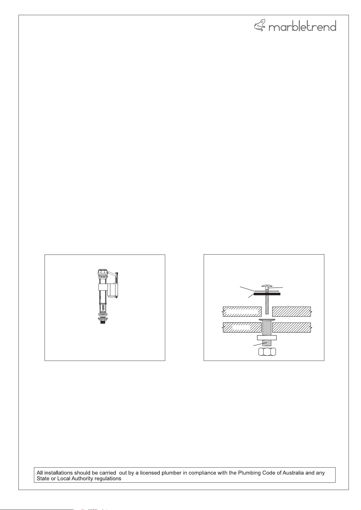
Note: for bottom water entry option a bottom water entry valve is required(not supplied). Refer to DIAGRAM 3.
9. Place the WC into position ensuring that it seals firmly to the pan connector
10. Insert the floor bracket fixing screws through the fixing holes in the base of the pan and tighten. Attach the
decorative caps.
11. For mortar bedding use a 4:1 sand and standard cement mix (do not use Rapid Hardening cement). If the
floor is tiled, cut out the tiles beneath the pan to create a good bonding surface.
12. Place the rubber foam sealing-ring in position and place the cistern in position on the WC pan. Check that
the rubber seal is seated correctly.
13. Secure the cistern to the pan by screwing the cistern fixing bolts and washers to the threaded insert in the
top of the cistern platform (the body of the outlet valve may be temporarily removed from the base to make
this easier). Screw down firmly to compress the foam seal ring. Refer to DIAGRAM 4
14. For back water entry - attach the inlet valve water supply hose to the water supply.
15. Always flush the water supply pipes before connecting the cistern inlet valve to the cistern tap.
16. Fill the cistern and check the water level, if necessary adjust the inlet valve float.
17. Attach the cistern lid and buttons and test flush several times while checking for leaks.
18. Waterproof sealant finishing may be used around the base of the WC.
19. Fit seat
HEX NUT
PLASTIC WASHER
BOLT
SS WASHER
THREADED INSERT
CISTERN FIXING BOLTS
ASSEMBLY
DIAGRAM 4
WC PAN
CISTERN BASE
RUBBER WASHER
OPTIONAL INLET VALVE (XI210) REQUIRED
FOR BOTTOM WATER ENTRY INSTALLATIONS
FLUSH WATER VOLUME TO BE ADJUSTED TO
THE LEVEL MARK ON THE CISTERN
DIAGRAM 4

MILANO FLUSH TO WALL SUITE Code J1426
WARNING
DO NOT USE CHLORINE/CHEMICAL
SANITISERS IN THE CISTERN TANK.
SUCH USE MAY RESULT IN DAMAGE TO
TANK COMPONENTS AND WILL VOID
THE PRODUCT WARRANTY
TURN SCREW
TO RAISE/LOWER
FLOAT
It is possible for dirt/debris to prevent the valve shutting off.
To remedy this the diaphragm may be cleaned as follows:
1. Unclip the float arm from the adjustment screw
2. Twist the plastic top-asembly firmly anti-clockwise and
remove it from the valve body
3. Inspect both rubber diaphragm and valve seat. Rinse
under running water to remove dirt/debris
5. Re assemble in reverse order
1. Water level adjustment
INLET VALVE SERVICE
2. Cleaning the diaphragm
Valve may be removed for
service - twist to unlock
Button rods must be just clear of
the valve pads
Button rods can be adjusted
by screwing up or down
Half
flush
Full
flush
Half flush volume can be adjusted by moving the side float up or down.
Moving the float DOWN increases the half flush
Moving the float UP decreases the half flush
The full flush volume can be adjusted by changing the residual water level in the cistern.
Move the adjuster DOWN to increase the volume.
Move the adjuster UP to decrease the volume.
OUTLET VALVE SERVICE
Removal Assembly Push button rod settings
Full flush adjustmentHalf flush adjustment
Ensure that buttons
match valve pads
Hoses are not shown on this
diagram
I0091MT
3/3
This manual suits for next models
1
Popular Toilet manuals by other brands

PolyJohn
PolyJohn PJN3 Series Product instructions

Clou
Clou CL/04.06060.20 installation instructions

Woodbridge
Woodbridge T-0047 Installation and care guide

Premier
Premier 1034390 Use and care guide

Toto
Toto Washlet GL TCF891G instruction manual

Raritan
Raritan Crown Head Installation, operation and maintenance instructions