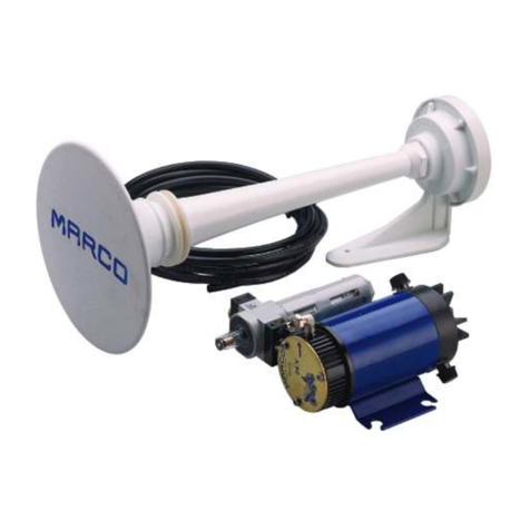
Marco EMH2 136 012 12 User manual

10/07/06Ed.00 Rev.01
EMH2 136 012 12 (12V)
EMH2 136 012 13 (24V)
2 Trombe elettroniche stagne + 2 nebbia +
VHF + stereo + microfono + 4 sirene
2 Waterproof electronic whistles + 2 fog
signals + VHF + stereo + microphone +
4 sirens

N.B.
Le funzioni di questo prodotto vengono attivate sia tramite cablaggio su morsettiera sia attraverso il
pannello di controllo opzionale collegabile all’unità elettronica principale tramite cavo RJ45 non
incrociato(pintopin)ad8politutticablati.
Se le funzioni vengono attivate utilizzando il cablaggio della morsettiera, devono essere disattivate
tramitecablaggiomedesimo.
Selefunzionivengonoattivateutilizzandoilpannellodicontrollo(SB,SB-MC,
SB-ML),devonoesseredisattivatetramiteilmedesimopannello.
PLEASENOTE.
Operations of this product are activated whether using wiring harness on terminal board or using the
control panel that can be connected to the electric unit through RJ45 cable 8 poles not crossed (pin to
pin).
Iffunctionsareactivatedwiththewiringharnessoftheterminalboard,theymustbedeactivatedusingthe
wiringharnessoftheterminalboard.
If functions are activated with the control panel ( SB, SB-MC,SB-ML), they must be deactivated using
thecontrolpanel.
Tromba elettronica stagna
12V/24V
Codice
136 012 12 (12V)
136 012 13 (24V)

Codice Articolo V A Potenza Sonora Frequenza
segnale
nebbia
Dimensioni del
Fischio Totale
Peso Kit Protezione
13601212 12 1,5
13601213 24 1
Potenza elettrica di
pilotaggio 12 W
Pressione acustica a 1
metro 115 dB (1/3 OCT.)
800Hz 154x121x132 1,900 kg IP 67
Tromba elettronica stagna
12V/24V
Codice
136 012 12 (12V)
136 012 13 (24V)
DESCRIZIONE DEL PRODOTTO
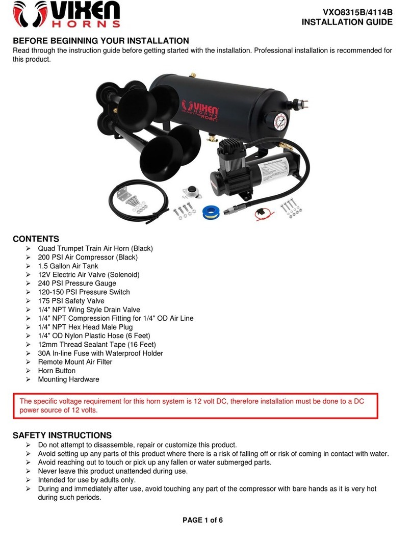
Avvisatore elettronico costituito da 2 gruppi altoparlante, microfono e centralina elettronica con funzioni
di:generatore800Hz,2segnaliautomaticidanebbia,amplificatoredivoce,entrataAux,stereo,4sirene.
DATI TECNICI
ISTRUZIONI PER L'INSTALLAZIONE ELETTRONICA DEL FISCHIO
E L’IMPOSTAZIONE DEI TONI ACUSTICI
Avvertenza importante. Allo scopo di garantire una perfetta tenuta, l’unità magnetodinamica (driver)
delgruppoaltoparlantevienefornitapre-cablataconcavostagnatolungo0,5mdisezione2x0,75mmq.
Il collegamento va quindi effettuato sul cavo con idonea scatola di derivazione. Non sostituire né il cavo
néaprirel’unità,lagaranziaaltrimentidecadrà.
1) Montare il gruppo altoparlante leggermente inclinato verso il basso per evitare il ristagno d’acqua
all’internodelcono.
2)Aprireilcoperchiodellacentralinaelettronicaed identificareleduemorsettierea viteda10e6 contatti
contrassegnati.
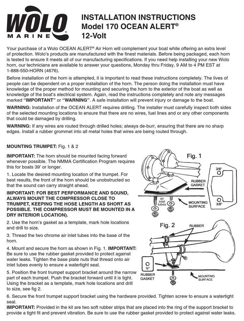
3)Eseguireicollegamentielettricicomedescrittonelloschemaallegato.
4)Collegamentiperattivazionefunzioni(fareriferimentoalloschemaallegato).
a. Tono Manuale. Per attivare manualmente un qualsiasi tono, collegare un PULSANTE alla
morsettierada10pintraimorsettimarcati1e2.Lamassimaduratadiuntonocontinuoèdi5”.
NOTA - QUESTO PULSANTE HA SEMPRE L'ASSOLUTA PRIORITA' SU TUTTE LE ALTRE
FUNZIONALITA',INCLUSOILMICROFONO.
b. Segnaleda Nebbia-75 secondi. Collegareun interruttoreallamorsettiera da10 pintrai morsetti
marcati 1 e 3. Con l' interruttore nella posizione chiusa si ottiene un segnale intervallato con pausa di
duratapredefinitapernebbia.Ilsegnaleèuntonodidurata5”.
c. Entrata AUX. L'ingresso AUX è un ingresso ausiliario bilanciato dell' amplificatore ( idoneo per
segnali VHF, radio, CD, mp3… ), che può accettare una tensione d'ingresso compresa tra 200mV e 3V
RMS. Eseguire i collegamenti sulla morsettiera da 6 pin tra i morsetti marcati “L” come indicato nel
dettaglio ingrandito.Attivare la funzione collegando l' interruttore tra i morsetti 1 e 2. Regolare il volume
del suono in uscita con il trimmer posto sopra tale morsettiera. Se il livello del suono è troppo basso pur
avendo regolato il trimmer al massimo o se il fruscio di fondo è elevato, è consigliabile invertire i
conduttoridisegnalesuidue“L”.
La morsettiera a 6 pin, ha la possibilità di ricevere anche una entrata stereo (3 way e 4 way), (vedere
collegamenti come da schema elettrico) riproducibile con i due altoparlanti. Sopra questa morsettiera ci
sonoduetrimmerdiregolazionedelsuonoinuscita(lefterightcomedaschemaelettrico).
d. Microfono.Collegareilmicrofonoallarelativapresamicrofonicaeregolareilvolumedelsuonoin
uscitaattraversoiltrimmerposizionatosoprailconnettoremicrofonico.Semicrofonoealtoparlantesono
ravvicinati e tali da innescare un fischio (effetto Larsen) ridurre il guadagno del microfono agendo sul
trimmer.

RISOLUZIONE DI PROBLEMI
Nelcasodimancatofunzionamentodelsistemaprocederecomesegue:
1) Verificare la continuità del fusibile ed eventualmente sostituirlo con pari caratteristiche: fusibile 3,15A
rapido.
2) Sconnettere il cavo dell’altoparlante della centralina e controllare con un tester la lettura in ohm tra i
duefili.
A) Se la lettura è zero (corto circuito) o infinito (circuito aperto), verificare l’integrità della linea
dell’altoparlanteesequestaècorrettainviareilsoloaltoparlantealcentroassistenza.
B) Se la lettura è compresa tra 6 e 9 ohm il gruppo altoparlante è funzionante e quindi inviare solo la
centralinaalcentroassistenza.
1)Ilperiododigaranziaèdi2annidalladatad'acquistocomerisultadallarelativafattura.
2) Nel caso la fattura non fosse disponibile il periodo di garanzia di 2 anni, sarà calcolato dalla data di
fabbricazione.
3)Lagaranziadecadees'intende nullaincasod'utilizzazionenon correttaonelcasovenissero ignorate
leistruzionicontenutenelpresentemanuale.
4)Lagaranziacopresolamenteidifettidifabbricazione.
5)Lagaranzianoncopreicosticonnessidiinstallazioneesmontaggio.
6)I costiditrasporto sonorimborsabilisolo nelcasoin cuilagaranzia è statadebitamente riconosciuta e
accettata da Marco S.p.A. Questi costi saranno limitati ai costi di spedizione tra il magazzino di Marco
S.p.A.elasededelcliente.
7) Nessuna nota di credito o reso sarà emessa prima di un test eseguito dal controllo di qualità di Marco
S.p.A.chedichiaridifettosoilprodotto.
GARANZIA
e. Sirena. Con la chiusura dell' interruttore nella posizione sirena (collegamento tra i morsetti 1 e 4
dellamorsettierada10pin)siottieneil tonosirena.
Esistono 4 tipi di sirena, selezionabili agendo sul dip switch come raffigurato nello schema elettrico.
Questointerruttore(collegamentotra imorsetti1 e4dellamorsettieraa 10pin)funge anchedasecondo
segnaledanebbia.
Questo secondo segnale da nebbia ha, come il primo, la possibilità di essere personalizzato (vedere
capitolo“personalizzazionedelsegnaledanebbia”).Questadupplicefunzione(FOG2 e S I R E N A ) è
selezionabileagendosuldipswitchallaposizionenumero2(vedereschemaelettrico).
Personalizzazionedelsegnaledanebbia
1)AttivareilSegnaledaNebbiaautomatico.
2) DURANTE LA FASE DI PAUSA DEL SEGNALE DA NEBBIA, premere il Pulsante Tono Manuale,
impostandoquindiunaseriediimpulsicorti/lunghiasceltaperunmassimodi8impulsi.
Nota - Toni corti(2”) e lunghi(5”) vengono automaticamente generati in base al tempo di pressione del
pulsante (pressione inferiore a 2” = tono di 2”, mentre pressione superiore a 2” = tono di 5”). Per
confermarela sequenza personalizzata bisognaposizionare l’interruttore del segnale da nebbia su OFF
entro10secondidall’ultimosegnaledellasequenzadi personalizzazione.Unbeepacustico,successivo
all’operazione (dopo 5 secondi), conferma la memorizzazione della sequenza personalizzata. Per la
personalizzazione del secondo segnale da nebbia la procedura è la medesima. L’unica differenza èche
sihannoduebeepsdiconfermadellapersonalizzazionedeltonoallafinedellaprocedura.
3) Per ripristinare il segnale predefinito occorre seguire la procedura di personalizzazione del tono da
nebbia,tenendopremutounasolavoltailpulsanteTonoManualeperuntemposuperioredi2”.
N.B.
Curare i cablaggi e seguire attentamente lo schema elettrico allegato. Mettere in fase gli altoparlanti
collegando i cavi “+” alla “A” rossa della morsettiera a 10 pin. Per l’entrata VHF collegare un cavo alla
“L” rossa e l’altro cavo alla “L” bianca. Per l’entrata stereo a tre vie collegare il cavo “right” alla “R”
rossa, il cavo “left” alla “L” rossa e il cavo “common” alla “L” bianca della morsettiera a 6 pin. Per
l’entrata stereo a quattro vie, i collegamenti sono come per la tre vie con l’aggiunta del secondo
“common” in corrispondenza della “R” bianca della morsettiera a 6 pin.

Product Code V A Acoustic Power Fog signal
frequency Horn Dimensions Total Kit
Weight protection
13601212 12 1,5
13601213 24 1
Pilot electrical power
12 W
Acoustic Pressure at
1 m 115 dB (1/3 OCT.)
800Hz 154x121x132 1,900 kg IP 67
INSTRUCTIONS FOR THE ELECTRICAL INSTALLATION OF THE WHISTLE
AND SETTING OF THE SIGNAL TONES
Waterproof electronic whistle
12V/24V
Codice
136 012 12 (12V)
136 012 13 (24V)
Electronic whistle complete with two loudspeakers, microphone and electronic unit with functions
of: 800 Hz frequency generator, 2 automatic fog signals, voice amplifier, 2 aux inputs (VHF and
stereo),4emergencysirens.
TECHNICAL DATA
Important Notice. In order to ensure complete water-tightness, the loudspeaker driver unit is
suppliedwitha factoryfittedelectricalcable 0.5mlong,tin-platedand2x0,75 sq.mmsection.Do
not replace this cable or open the driver unit, warranty will be invalidated. A suitable terminal
junctionboxshouldbeusedtocompletethecableconnections.
1.Mount the loudspeaker in a slightly downward tilt position in order to prevent water entrapment
insidethecone.
2.Open the Electronic Controller coverlid and identify the marked 8 pins terminal block and 4 pins
terminalblock.
3.Completetheelectricalinstallationasshownintheattachedwiringdiagram.
4.Devicewiringforfunctionsactivation(refertotheattachedinstallationdiagram)
a. Manual Tone. Toobtain amanually activated free tone, install apush button switch control
across the terminal contacts marked 1 and 2 on the 8 pins terminal block. The maximum duration
ofacontinuousblastis5”.
NOTE - THIS PUSHBUTTON HAS ALWAYS ABSOLUTE PRIORITY OVER ALL OTHER
FUNCTIONS,INCLUDINGTHEMICROPHONE.
b. FogHornSignal-75seconds.Afog-hornsignalrepeatedatspecifiedintervalsisobtained
connecting the switch in position closed (connections across the terminal pins marked 1 and 3 on
the8pinsterminalblock).Thesignalisatoneof5”duration.
c. AUX Input. Amplifierauxiliary input ( suitable for signals : VHF, radio,CD, mp3…). Voltage
inputrange :200mV…3VRMS. Maketheconnections on the6-pinterminal block betweenthe“L”
terminals as illustrated in the enlarged drawing detail. Activate the function by connecting the
switch between terminals 1 and 2. Adjust the level of the output sound with the trimmer located
beside the terminal block. If the sound level is not loud enough, even with the trimmer at the
extreme position, or if the background noise is high, please reverse the connections of the two
signalwiresmarkedwith“L”.
The6-pin terminal block has the possibility of receiving a stereo input (3-way and 4-way), (see the
electrical diagram showing how to make the connections) and transmit through both
loudspeakers.Twotrimmersarelocatedoverthisterminalblocksothatexitsoundcanbeadjusted
(leftandrightasshownondiagram)
d. Microphone. Connect the microphone to the microphone socket, then adjust the output
level with the trimmer located in the middle of the printed circuit board. Depending on relative
position and distance of microphone and loudspeaker the Larsen effect may occur, in this case
reducethegainwiththetrimmer.
PRODUCT DESCRIPTION

e. Siren. The siren tone is obtained with the switch in the siren position (connections across the
terminalpinsmarked1and4onthe10pinterminalblock).
There are 4 types of siren tones available, they can be selected by changing the dip switch position as
youcanseefromthewiringdiagram.
The second fog signal is obtained with the same switch, in the same position as for the siren tone
(connectionsacrosstheterminalpinsmarked1and4onthe10pinterminalblock).
Modify the dip switch position as shown in the wiring diagram, to pass from the siren tone to the second
fogsignal.
The second fog signal can be personalized as the first one (see chapter “procedure to set a customized
tone”). This double function (FOG2 and SIRENA) is selectable acting on the dip switch in the position
number2(seeelectricdiagram).
Proceduretosetacustomizedtone
1)ActivatetheautomaticFogHornswitchcontrol.
2) Input a chosen series of short/long tones, maximum 8 tones, DURING THE PAUSE INTERVAL
PHASEOFTHEFOGHORNCYCLE,bypressingtheManualTonepushbuttonaccordingly.
Note - Short(2”) and long(5”) tones are automatically generated depending on the activation time of the
pushbutton (activation time shorter than 2” = a short tone, while activation time longer than 2” = a long
tone).Toconfirm the customized sequence you have to put thefog signal switch on “OFF”position by 10
sec. from latest sound of customized sequence. One sound beep follow this operation (5 seconds) and
confirmthememorisation of customized sequence. The procedure to customizethe second fog signal is
the same. The only difference is that the memorisation of customized sequence is confirmed by two
soundbeeps.
3)Tore-instatethedefaultsignalfollowup customisationtone procedures bypressingtheManualTone
pushbuttonwithasingleimpulselongerthan2”.
PLEASE NOTE
- Pay attention to the cables and carefully follow the wiring diagram attached.
- Timing the loudspeakers, connecting the “+” cables to the red “A” on the 10 pin terminal block.
- For the VHF input connect a cable to the red “L” and the other cable to the white “L”.
- For the three-way stereo input, connect the “right” cable to the red “R” , the “left” cable to the
red “L” and the “common” cable to the white “L” on the 6 pin terminal block.
- For the four-way stereo input, connect the “right” cable to the red “R” , the “left” cable to the
red “L”, the first “common” cable to the white “L” and the second “common” cable to the white
“R” on the 6 pin terminal block.
PROBLEM RESOLUTION
Inthecaseofasystemmalfunctionproceedasfollows:
1.Checkfusecontinuityandreplaceifnecessary:fastblowfuse3,15A.
2.Disconnect loudspeaker connections at the controller box and check the Ωreading between the
connectionsusingatester.
A)If readingiszero (short circuit)orinfinity (open circuit),verifythe loudspeaker linecontinuityand if this
isok,buttheproblempersiststhenreturnonlythedrivertoyourCostumerServiceCentre.
B) If reading is between 6 - 9 ohm, then the loudspeaker unit is functional and only the electronic
controllerboxshouldbereturnedtoyourCostumerServiceCentre.
1) The Warranty period is 2 years from date of purchase on production of the appropriate sales
invoice.
2) Should the original sales invoice not be available, then the 2 year warranty period will be valid
from date of production.
3) The Warranty becomes null and void in the case of incorrect utilization or disregard of the
instructions contained herein.
4) The Warranty only covers original production defects.
5) The Warranty does not cover any related installation costs involved.
6) Transport costs are refundable only in the case where warranty has been duly recognized and
accepted by Marco Spa. These costs will be limited to the actual shipment costs between Marco Spa
warehouse and the client's delivery address.
7) No credit notes or replacement items will be issued prior to the receipt and proper testing of any
Marco goods that are deemed faulty.
WARRANTY

2
AAA A
AAA A
A A A A
1
2
3
4
LLR
Left
Right
Common / Comune
STEREO 3 way
MONO
4
FOG 2
3
SIRENAN°1=AMBULANZAE VV.FF.
ITALIANAMBULANCE
SIRENAN°2=POLIZIAE CARABINIERI
ITALIAN POLICE
SIRENAN°3=STANDARDAMERICANA
AMERICAN STANDARDS
2
1
2
1
2
1
2
1
LLRR
1234
1 2 R
12
1 2 3 4
Regolazione guadagno microfono
MIC gain trimmer
Regolazione guadagno VHF e “LEFT” (stereo)
VHF and “LEFT” (stereo) gain trimmer
Regolazione guadagno “RIGHT” (stereo)
“RIGHT” (stereo) gain trimmer
Connettore microfono
MIC connection
FUNZIONI DIP SWITCH
DIP SWITCH
“YELP”
“HI-LO”
SIRENAN°4=STANDARDAMERICANA
AMERICAN STANDARDS
FOG 2 / Siren switch
Interruttore secondo segnale da nebbia /
sirena
STEREO
SIRENA
Common / Comune
STEREO 4 way
MONO
OPTION 1
OPTION 2
OPTION 3
8 Ohm loudspeaker
Altoparlante 8 Ohm
8 Ohm loudspeaker
Altoparlante 8 Ohm

DICHIARAZIONE DI CONFORMITA’ C.E.
E.C. DECLARATION OF CONFORMITY
Confermiamo che il prodotto:
We confirm that the product:
136 012 012 - EMH2 12V Trombe elettroniche stagne / Waterproof electronic whistles
136 012 013 - EMH2 24V Trombe elettroniche stagne / Waterproof electronic whistles
Questa dichiarazione è rilasciata sotto la responsabilità esclusiva di:
This declaration is given under the sole responsibility of:
MARCO S.P.A.
Via Mameli 10 - 25014 Castenedolo - Brescia - Italy
Tel. 030/2134.1 Fax 030/2134.300
Questa dichiarazione è valida per tutti gli articoli prodotti secondo la documentazione tecnica che è parte di questa
dichiarazione. In caso di eventuali verifiche pertinenti alla Compatibilità Elettromagnetica sono state applicate le
seguenti normative:
This declaration is valid for all products which are produced in accordance with the technical documentation which is
a part of this declaration. For verification of conformity with regard to Electromagnetic Compatibility the following
standards are applied:
EN 60945 2002-10 Apparecchiature e sistemi di navigazione marittima e di radiocomunicazione
Prescrizioni generali - Metodi di prova e risultati delle prove richieste
Maritime navigation and radio communication equipment and system
General requirements - Methods of testing and required test results
E’ conforme alla Direttiva 2004/108/CE (ex.89/336/CE) relativa alla Compatibilità Elettromagnetica.
.
Is in conformity with the Directive 2004/108/EC (ex.89/336/EC) relating to Electromagnetic Compatibility.

Per ulteriori informazioni vedere sito internet - www.marco.it
Marco S.p.A via Mameli 10 - 25014 Castenedolo - Brescia - Italy
tel. +39 030 2134.1 / Fax +39 030 2134.300
For further information visit the web site - www.marco.it
Marco S.p.A via Mameli 10 - 25014 Castenedolo - Brescia - Italy
tel. +39 030 2134.1 / Fax +39 030 2134.300
This manual suits for next models
3
Table of contents
Other Marco Horn manuals
Popular Horn manuals by other brands

nedis
nedis MEPH200WT manual

COMPRO
COMPRO CO BL HP 582 G 24/230 Series quick start guide

UTC Fire and Security
UTC Fire and Security Ziton ZP755HA-2 Installation sheet

Vixen Horns
Vixen Horns VXO8530/3118 Nstallation guide

Vixen Horns
Vixen Horns VXO8705/3118B installation guide

Vixen Horns
Vixen Horns VXO8805/3118B installation guide

Monacor
Monacor TM-6 instruction manual

Vixen Horns
Vixen Horns VXO8330/1170C installation guide

Vixen Horns
Vixen Horns VXO8330BDP installation guide

Vixen Horns
Vixen Horns VXO4830AB/4124XB installation guide

Valcom
Valcom VIP-490AL quick start guide

Cooper Notification
Cooper Notification AMT-12/24 installation instructions