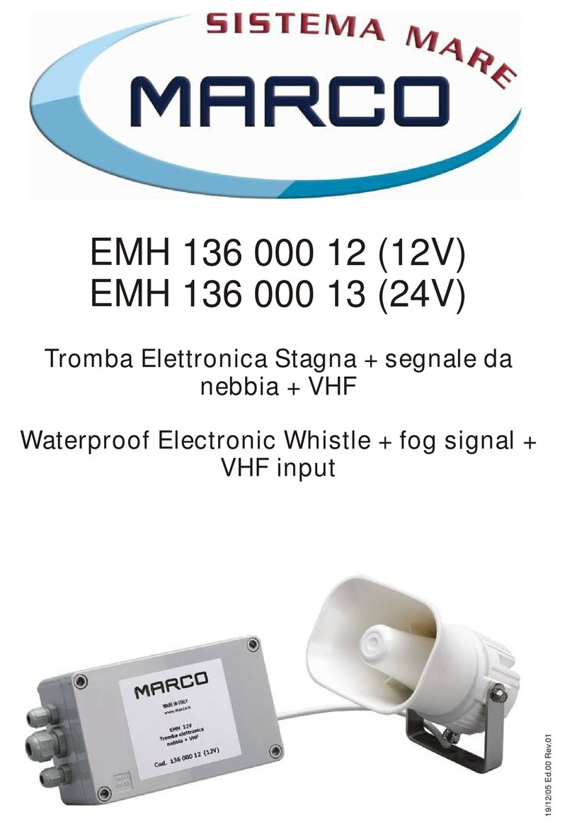
Marco PW2 150 000 12 User manual

PW2 150 000 12 (12V)
PW2 150 000 13 (24V)
Fischio Pneumatico Omologato
(Trombe per imbarcazioni da 12m a 20m)
Approved Pneumatic Whistle
(Marine Horns for vessels between 12m to 20m in length)
20/12/05Ed.00 Rev.01

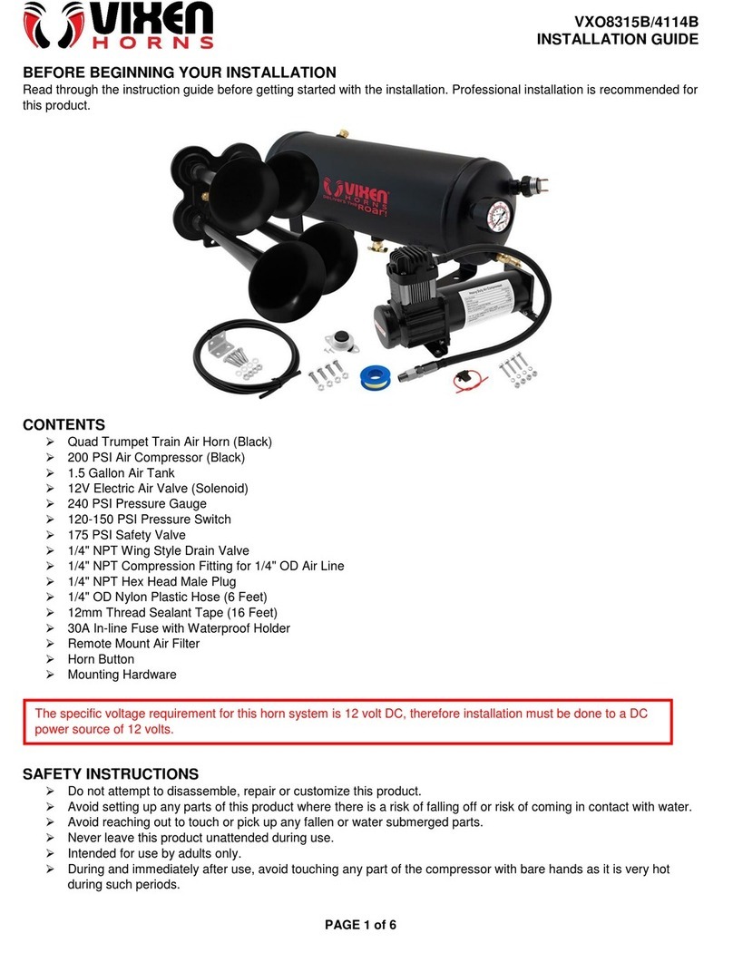
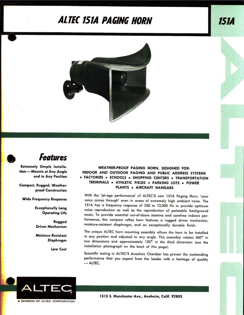
Avvisatore sonoro omologato completo di tromba ø200mm verniciata bianca, compressore
elettrico e accessori di montaggio. Omologazione RINA, LLOYD’S REGISTER MCAe BUREAU
VERITASinaccordoallenormeinternazionaliCOLREG1972IMOclasseIV.
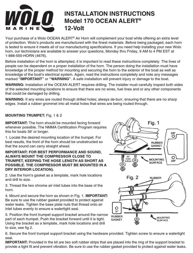
1. Montare la tromba inclinandola leggermente verso il basso (5°) per evitare il ristagno
d'acquaall'internodelcono.
2. Collegare il gruppo altoparlante al compressore attraverso il tubo rilsan ed utilizzando gli
accessoridelkitcomedaschemaallegato.
3.Montareillubrificatorecomedasequenzafotografica.
4.FissareilcompressoreadunpianocondellevitiM5.Utilizzaregliappositiantivibrantiingomma
inmododaevitarelevibrazioniduranteilfunzionamento.
5.Collegareilpulsantediazionamentoinseriealcavorosso.Sulmedesimocavoèstatomontato
unfusibilelamellare.
6.Collegare l’estremodelcavo rossoal polopositivodella betteria(+) el’estremodel cavoneroal
polonegativodellabatteria(-).
Fusibilelamellare(40Aa12Ve30Aa24V)
Pulsantediazionamentofornito
Sezionedeicavi:
Percollegamentiallabatteriafinoa5metri: 2,5mmqper24V
4,0mmqper12V
Percollegamentiallabatteriafinoa10metri: 4,0mmqper24V
6,0mmqper12V
Nelcasodimancatofunzionamentodelsistemaprocederecomesegue:
1.Verificarelacontinuitàdelfusibileedeventualmentesostituirlo.
2. Verificare che il lubrificatore sia regolato correttamente. Una eccessiva lubrificazione può far
arrivarel’olioconlesueimpuritàallamembranabloccandoneilfunzionamento.Intalcasobisogna
smontarelatromba,pulirelemembrane,erimontareiltutto.
3. Piccoli corpi solidi come ad esempio limatura di metallo possono causare lo stesso
inconveniente.Intalcasoprocedereallapuliziacomedettoprecedentemente.
4. Una eccessiva lubrificazione comporta un intasamento del compressore e del tubo di
collegamentocompressore-tromba.Intalecasoscollegareiltubodallatrombaefargirareavuoto
ilcompressoreinmododaeliminarel’olioineccesso.
DATI TECNICI
ISTRUZIONI PER L'INSTALLAZIONE DEL FISCHIO
DATI TECNICI ELETTRICI
DESCRIZIONE DEL PRODOTTO
RISOLUZIONE DI PROBLEMI
Fischio Pneumatico 12V/24V
Tromba Nautica per imbarcazioni da 12m a 20m
Codice
150 000 12 (12V)
150 000 13 (24V)
PW2 150 000 12 12 20 123 630 460x200 1
PW2 150 000 13 24 10 123 630 460x200 1
TIPO CODICE V A dB (1/3 OCT.)(1m) Hz DIMENSIONI (mm) PEZZI PER CARTONE

FUSIBILE
30A 12V
25A 24V
ANTIVIBRANTE
VITE M5
SEQUENZA DI MONTAGGIO MEMBRANE
Membrana
Membrana forata
Coperchio Viti Fondello Guarnizione
Guarnizione Base
All’interno dellatromba sonomontate duemembrane insequenza ordinata.In casodi apertura,e
successivamanutenzione,rimontarelestesserispettandol’ordinecomeseguedaesploso.
Ilcoperchioposterioreèapplicatoapressione.
Peril fissaggiodella trombavengonoforniti duetubi filettatiin duediversemisure. Nellanecessità
di utilizzare un tubo ancora più corto, tagliare l’asta filettata e pulire accuratamente in modo da
eliminarequalsiasiresiduodimetalloprimadiavvitaresulgruppoaltoparlante.
+
-BATTERIA 12/24V
PULSANTE
LUBRIFICATORE
TUBO RILSAN øest 8 mm
øint 6 mm
SCHEMA DI COLLEGAMENTO
ATTENZIONE

1)Ilperiododigaranziaèdi2annidalladatad'acquistocomerisultadallarelativafattura.
2)Nelcasolafatturanonfossedisponibileilperiododigaranziadi2anni,saràcalcolatodalladata
difabbricazione.
3) La garanzia decade e s'intende nulla in caso d'utilizzazione non corretta o nel caso venissero
ignorateleistruzionicontenutenelpresentemanuale.
4)Lagaranziacopresolamenteidifettidifabbricazione.
5)Lagaranzianoncopreicosticonnessidiinstallazioneesmontaggio.
6) I costi di trasporto sono rimborsabili solo nel caso in cui la garanzia è stata debitamente
riconosciuta e accettata da Marco S.p.A. Questi costi saranno limitati ai costi di spedizione tra il
magazzinodiMarcoS.p.A.elasededelcliente.
7) Nessuna nota di credito o reso sarà emessa prima di un test eseguito dal controllo di qualità di
MarcoS.p.A.chedichiaridifettosoilprodotto.
123
4 5
La regolazione della lubrificazione avviene agendo su questa
piccola vite. Svitando la vite in ottone con un cacciavite a taglio,
aumenta il flusso di olio ed aumenta di conseguenza la
lubrificazionedellemembrane.
Avvitando la vite diminuisce il flusso di olio e diminuisce
conseguentementelalubrificazionedellemembrane.
Per il riempimento utilizzare l’olio in dotazione. Gli altri riempimenti
dovranno essere effettuati utilizzando olio specifico per lubrificatori
o, in alternativa, olio tipo ISO VS32, oppure olio automobilistico
SAE30.
SEQUENZA DI MONTAGGIO DEL LUBRIFICATORE
REGOLAZIONE LUBRIFICATORE
GARANZIA

Approved signalling whistle complete with white painted horn ø200 mm, with electric compressor
and mounting accessories. Meets COLREG 1972 IMO class IV regulations. Approvals. RINA,
LLOYD’SREGISTERMCAandBUREAUVERITAS.
1. Install the horn angled slightly downward (5°)in order to avoid the water stagnation
withinthecone.
2.ConnecttheloudspeakertothecompressorthroughtheRilsanpipeutilizingtheaccessorizesof
thekit,seethelayoutattached.
3.Installtheoilcontainerasshowninthephotographicsequence.
4. Fix the compressor to a flat surface using M5 screws. Use the rubber vibration-damping in
ordertoavoidanyvibrationsduringtheexecution.
5. Connect in series the service switch to the red cable. On the same cable a lamellar fuse has
beeninstalled.
6. Connect the extreme part of the red cable to the positive pole of the battery (+) and the extreme
partoftheblackcabletothenegativepoleofthebattery(-).
INSTALLING INSTRUCTION OF THE WHISTLE
ELECTRICAL TECHNICAL DATA
Lamellar fuse (40A at 12V and 30A at 24V)
Service switch supplied
Section of cables:
For connections to the battery up to 5 meters : 2,5 mmq per 24V
4,0 mmq per 12V
For the connections to the battery up to 10 meters: 4,0 mmq per 24V
6,0 mmq per 12V
Inthecaseofasystemmalfunctionproceedasfollows:
1.Checkthecontinuityofthefuseandeventuallychangeit.
2. Check that the oil container is set correctly. If there is an excessive amount of oil, its impurities
can reach the membrane blocking the normal performance of the whistle. In this case dismantle
thehorn,cleanthemembranesandre-assemble.
3. Small solid bodies such as filings of metal can cause the same problem . In this case clean the
membranesassaidabove.
4. Excessive lubrication causes a stoppage of the compressor and of the pipe which connects the
compressor with the horn. In this case disconnect the pipe from the horn and run dry the
compressortodisposeoftheexcesslubrication.
PRODUCT DESCRIPTION
TECHNICAL DATA
PROBLEM RESOLUTIONS
Pneumatic Whistle 12V/24V
Marine Horns for vessels between
12m to 20m in length
Code
150 000 12 (12V)
150 000 13 (24V)
PW2 150 000 12 12 20 123 630 460x200 1
PW2 150 000 13 24 10 123 630 460x200 1
Hz DIMENIONS (mm) PCS. X CARTONdB (1/3 OCT.)(1m)TYPE PART NUMBER V A

FUSE
30A 12V
25A 24V
VIBRATION-DAMPING
SCREW M5
+
-BATTERY 12/24V
SWITCH
OILER
RILSAN PIPE øout 8 mm
øin 6 mm
Withinthehorn,twomembraneshavebeeninstalledinsequence.Wheneverthewhistlehasbeen
openedtocleanthemembranesithastobereassemblefollowingthedrawingquotedunderneath.
Thelid,whichclosesthehorn,ispressured.
Tofixthe horntwo threadedpipes aresuppliedintwodifferentmeasurements.Cutpart ofthepipe
offifshorterpipedisrequired.Makesuretocleanthepipeproperlyafterwardsinordertoeliminate
anymetalremains.Thereaftertightenittothebaseoftheloudspeaker.
CONNECTION LAYOUT
MEMBRANE ASSEMBLING SEQUENCE
membrane
Holed Membrane
Lid Screws
Cover Gasket
Gasket Base
WARNING

123
4 5
OILER ASSEMBLING SEQUENCE
The lubrication is regulated by means of this small screw.
Unscrewing the brass screw, using a screwdriver increases the oil
flowandconsequentlythelubricationofthemembranes.
While screwing the brass screw, decreases the oil flow and
thereforethelubricationofthemembranesisreduced.
For the first time filling use the oil supplied in the kit. For future
refilling use lubricator specific oils or, alternately, ISO VS32 type oil
orSAE30automotiveoil.
OILER REGULATION
1) The Warranty period is 2 years from date of purchase on production of the
appropriate sales invoice.
2) Should the original sales invoice not be available, then the 2 year warranty
period will be valid from date of production.
3) The Warranty becomes null and void in the case of incorrect utilization or
disregard of the instructions contained herein.
4) The Warranty only covers original production defects.
5) The Warranty does not cover any related installation costs involved.
6) Transport costs are refundable only in the case where warranty has been duly
recognized and accepted by Marco Spa. These costs will be limited to the actual
shipment costs between Marco Spa warehouse and the client's delivery address.
7) No credit notes or replacement items will be issued prior to the receipt and
proper testing of any Marco goods that are deemed faulty.
WARRANTY


Per ulteriori informazioni vedere sito internet - www.marco.it
Marco S.p.A via Mameli 10 - 25014 Castenedolo - Brescia - Italy
tel. +39 030 2134.1 / Fax +39 030 2134.300
For further information visit the web site - www.marco.it
Marco S.p.A via Mameli 10 - 25014 Castenedolo - Brescia - Italy
tel. +39 030 2134.1 / Fax +39 030 2134.300
This manual suits for next models
1
Table of contents
Languages:
Other Marco Horn manuals
Popular Horn manuals by other brands

Vixen Horns
Vixen Horns VXC8301 installation guide

Vixen Horns
Vixen Horns VXO8350/1167C installation guide

Vixen Horns
Vixen Horns VXO8580/4114C installation guide

Cooper Notification
Cooper Notification AMT-12/24 installation instructions

Vixen Horns
Vixen Horns VXO8350/4124XC installation guide

Vixen Horns
Vixen Horns VXH2411C installation guide