Marconi 6313 User manual

Operating Manual
H 6313
Vol. 1
10 MHz to 26.5 GHz
PROGRAMMABLE SWEEP GENERATOR
6313
••
©Marconi Instruments Ltd. 1988
No part of this book may be reproduced or transmitted in any form
or
by
any means, electronic or mechanical, including photocopying,
or recorded by any information storage or retrievat system, without
permission in writing
by
Marconi Instruments Ltd.
Printed in the UK
Manual
pari no.
46881-852A
Print code :
8-8/89
Aug. 89

CONTENTS
Page
Preface
iii
Operating precautions iv
Chapter 1 GENERAL INFORMATION
1-1
Chapter 2 INSTALLATION
2-1
Chapter
3
OPERATION
3-1
3.1
Local operation
3.2 Programmable keys
3.3 Private GPIB operation
3.4 Operation with 6500
3.5
Calibration
3-1
3-33
3-51
3-53
3-63
Appendix A Sweeper parameters
Appendix B Sweeper memory facilities
Appendix C Counter Interface
Appendix D Self test
Appendix
E
Error messages
Index v
List of tables ix
List of figures ix
ASSOCIATED PUBLICATIONS
GPIB Operating Manual, H 6313 Vol. lA
Service Manual. H 6313, Vol. 2
Part No.
46881-853Z
46881-852A
Ii
46881-852A
Aug. 89
L
I
I
Ioio

PREFACE
WARNINGS, CAUTIONS AND NOTES
These terms have specific meanings in this manual:-
WARNINGS contain information to prevent personal injury.
CAUTIONS contain information to prevent damage to the equipment.
Notes contain important general information.
HAZARD SYMBOLS
The meaning of hazard symbols appearing on the equipment is as follows:-
Symbol Nature of hazard Reference In manual
&
Dangerous voltages Page iv
~Static sensitive components Page iv
Lh
Precision ·connector Page 3-2
MANUAL AMENDMENT STATUS
Each page in this manual bears the date of its original issue or, if it has been amended,
the date and status number of the latest amendment. Any changes subsequent to the
latest amendment status are included on Manual Change sheets coded Ct , C2 etc. at the
front of the manual. .
46881-852A
Aug. 89
jjj

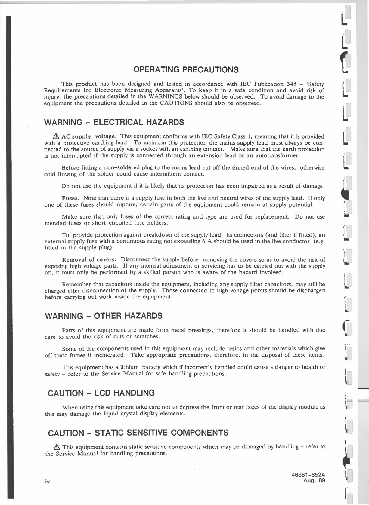
OPERATING PRECAUTIONS
This product has been designed and tested in accordance with IEC Publication 348 - 'Safety
Requirements for Electronic Measuring Apparatus'. To keep it in a safe condition and avoid risk of
injury, the precautions detailed in the WARNINGS below should be observed. To avoid damage to the
equipment the precautions detailed in the CAUTIONS should also be observed.
WARNING - ELECTRICAL HAZARDS
&
AC supply voltage. This equipment conforms with IEC Safety Class
1,
meaning that it is provided
with aprotective earthing lead. To maintain this protection the mains supply lead must always be con-
nected to the source of supply via a socket with an earthing contact. Make sure that the earth protection
is not interrupted if the supply is connected through an extension lead or an autotransformer.
Before fitting a non-soldered plug to the mains lead cut off the tinned end of the wires, otherwise
cold flowing of the solder could cause intermittent contact.
Do not use the equipment if it is likely that its protection has been impaired as a result of damage.
Fuses. Note that there is a supply fuse in both the live and neutral wires of the supply lead.
If
only
one of these fuses should rupture, certain parts of the equipment could remain at supply potential.
Make sure that only fuses of the correct rating and type are used for replacement. Do not use
mended fuses or short-circuited fuse holders.
To provide protection against breakdown of the supply lead, its connectors (and filter if fitted), an
external supply fuse with a continuous rating not exceeding
6 A
should be used in the live conductor (e.g.
fitted in the supply plug).
Removal of covers. Disconnect the supply before removing the covers so as to avoid the risk of
exposing high voltage parts.
If
any internal adjustment or servicing has to be carried out with the supply
on. it must only be performed by a skilled person who is aware of the hazard involved.
Remember that capacitors inside the equipment. including any supply filter capacitors, may still be
charged after disconnection of the supply. Those connected to high voltage points should be discharged
before carrying out work inside the equipment.
WARNING - OTHER HAZARDS
Parts of this equipment are made from metal pressings, therefore it should be handled with due
care to avoid the risk of cuts or scratches.
Some of the components used in this equipment may include resins and other materials which give
off toxic fumes if incinerated. Take appropriate precautions, therefore, in the disposal of these items.
This equipment has a lithium battery which if incorrectly handled could cause
a
danger to health or
safety - refer to the Service Manual for safe handling precautions.
CAUTION - LCD HANDLING
When using this equipment take care not to depress the front or rear faces of the display module as
this may damage the liquid crystal display elements.
CAUTION - STATIC SENSITIVE COMPONENTS
&
This equipment contains static sensitive components which may be damaged by handling - refer to
the Service Manual for handling precautions.
iv
46881-852A
Aug. 89
-
~
{
L
l
L
L
•
I
l-
f,
)
••
L
~-'
IL
I
j
r

I
Chapter 1
GENERAL INFORMATION
FEATURES
Performance
The 6313 is a programmable sweep generator with a range of 10 NIHz to 26.5 GHz.
It provides a combination of frequency and power sweeps with a typical accuracy
of 20 MHz and ±0.4 dB. When used with Marconi Instruments' 6500 Automatic
Amplitude Analyzer it forms a scalar measurement system with a private GPIB to
enhance the performance of the 6500, as well as a system GPIB to allow operation as part
of a complete automatic test system.
Control and display
Logically arranged keypads. with step keys and a rotary control allow rapid manual
operation. A large, backlit LCD display shows operating status, current values of
controlled parameters, and the current functions of four 'soft' keys. The 6313 can also be
fully controlled via the GPIB.
--
----
Fig.
1-1
Programmable Sweep Generator
6313
with Automatic Amplitude Analyzer 6500
46881-852A
Aug. 89 1-1

GENERAL INFO~MAT10N
Soft keys and configuration keys
In normal operation, some or all of the four soft keys have one operating parameter
assigned to each of them. Selection of a soft key allows the value or state of the
parameter associated with it to be changed.
Parameters are assigned to the soft keys according to which 'configuration' (group
of parameters) has been selected.
There are fifteen pre-programmed configurations currently available on the 6313,
for example:
Configuration Associated parameters
[FI - F2] Start frequency eFI), stop frequency (F2)
power level (PI), sweep time (TIME).
Internal/external sweep (sweep), sweep trigger
(swp_tr), single sweep initiation (s_swp),
counter trigger (cntr_tr).
The pre-programmed configurations are accessed by labelled 'configuration keys'.
Additionally, there are six 'user-programmable' keys, which allow you to store and access
your own configurations to match a particular application (see 'User programming').
[SWPfTRG]
Operating mode/sweep configurations
There are four basic operating modes:
1) Frequency sweep at constant power.
2) Frequency sweep with power slope.
3) Constant frequency and power.
4) Constant frequency with power sweep.
The frequency sweep can be defined either between lower and upper limits
(Fl -
F2) or as a frequency span about a centre frequency (CF - ~F). These two alternatives
for the definition of the frequency sweep give a total of six 'sweep configurations', each
accessed by a labelled configuration key.
Markers
Up to five frequency markers may be set within a sweep. These enable you, for
example, to stop the sweep at some nominal frequency and accurately measure that
frequency using a counter. Another application is the setting of secondary limits within
the total sweep, to allow both in-band and out-of-band testing.
Memories
Twenty non-volatile memories can each store complete sweeper settings.
The contents of the memories can be reviewed one after the other using the step
keys or rotary control. While reviewing the memories, the RF output is switched off to
avoid any risk of damage to sensitive test pieces.
1-2 46881-852A
Aug. 89
f .
I
"
\
I
r .
l

GENERAL
INFO~MATION .
Any memory setting can be chosen as the power-up condition, so that repetitive
testing can begin immediately after switch-on.
User programming
The PROG key enables you to create and store (in non-volatile memory) up to six of
your own configurations. These can then be accessed via the six 'user-programmable'
configuration keys.
Applications of this facility include the ability to further simplify operation by
masking non-critical parameters and adding relevant parameters which could otherwise
only be accessed by selecting another configuration key. A real-time clock can also be
added to the display to allow the timing of a test procedure.
If required, all frequency information may be removed from the screen for security.
User calibration
The output power and frequency of 6313 may be simply re-calibrated to match
special measurement conditions. A complete user calibration might be necessary, for
example, where a long cable intervenes between the 6313 and the test piece, or where
there is a high ambient temperature. A limited calibration can also be performed over a
specified part of the sweeper's frequency range.
Using Marconi Instruments RF Power Meter 6960 or
6960A
(with Sensor 6913) and
the 26.5 GHz Microwave Counter 2442 connected to 6313's Private GPIB, full re-
calibration takes approximately 20 minutes.
Two sets of complete user calibration data and two sets of limited calibration data
can be held in non-volatile store while the primary calibration is also retained.
User calibration is only allowed after entry of special authorization codes which are
contained in a document which accompanies each sweeper. The primary calibration is
doubly protected in this way. All re-calibration may be disabled by the setting of an
internal switch.
The display indicates whether primary, user or limited calibration is in use.
Scalar analysis
The 63J 3 with Marconi Instruments' 6500 Automatic Amplitude Analyzer form a
complete scalar network analysis system.
Measurements which can be made include:
Return loss
Voltage Standing Wave Ratio (VSWR)
Gain
Insertion loss
Gain compression
Absolute power
Connection between the 6313 and the 6500 via the Private GPffi allows intelligent
interaction between the instruments which greatly enhances the performance of the 6500.
Details of the operation of the 6313 with the 6500 are given in Chap. 3-4.
46881-852A
Aug. 89
1-3

GENERAL INFORJVlATION
System GPIB operation
Over 170 commands allow full control via the system GPIB. In addition to those
commands which are equivalent to front panel key operations, others allow fast data
transfer, text display and other facilities.
RF generation
The 6313 uses fundamental YIG tuned oscillators operating in the bands 2-8 GHz,
8-12.4 GHz and 12.4-20 GHz and 20-26.5 GHz. These provide the sweeper with a very
pure output having low harmonic and sub-harmonic components. Coverage to 10 MHz
is achieved by employing a frequency down-converter in conjunction with the 2-8 GHz
oscillator. All four YIG oscillators are kept running while the sweeper is switched on to
increase stability and reduce band switching times. Switching between oscillators is by
means of a PIN switch which gives a typical band switch delay of 0.5 IJ.S. The levelling
circuit uses a wide band coupler and detector diode for the 2 GHz to 26.5 GHz band and
an additional coupler/diode for the 10 MHz to 2 GHz band.
Digital correction data for all significant frequency values and power levels are
stored in memory, and applied to the sweep.
The FM input allows direct access to the YIG oscillators so that external frequency
locking devices may be used.
The RF on/off key has an integral LED to indicate whether or not the output is
enabled. The LCD gives an UNLV (unlevelled) display
if
the output power is no longer
levelled; for instance if the output power is greater than the set power level at low power
levels, or less than the set power level at high power levels. UNLV is also displayed when
the output is switched off. Levelled power is guaranteed over the range -5 to +10 dBm
(+7 dBm above 18 GHz).
1-4 46881-852A
Aug. B9
L
l
r
L
l
[
t:
.1
L
,
I
,
[
L
f'
L
L
(
'-
l
L

I
I
I
'I
PERFORMANCE DATA
Frequency
Range:
Resolution:
Display resolution:
Accuracy at caJ. temp
Fl and CW:
CF, F2, sweep modes
at 100 ms sweep or slower:
Stability
With temperature:
With 10% supply
voltage change:
With 10 dB power level
change:
With 3:1 load VSWR
at
+
10 dBm output
(+7
dBm for 18-26.5 GHz)
10 MHz to 2 GHz:
2 GHz to 8 GHz:
8 GHz to 12 GHz:
12 GHz to 20 GHz:
20 GHz to 26.5 GHz:
With time at constant temp.
after 1 hour warm up:
Residual PM
(in 10Hz to 10kHz bandwidth
CW mode with filter on)
1011Hz to 2 GHz:
2 GHz to 8 GHz:
8 GHz to 12 GHz:
12 GHz to 20 GHz:
20 GHz to 26.5 GHz:
46881-852A
Aug. 89
GENERAL INFORMATION
0.01 GHz to 26.5 GHz.
500 kHz in all modes.
10kHz in CW vernier mode, manually
(rotary control) and with GPIB control.
100 kHz in all modes.
±10 MHz max., ±3 :MHz typical at 23°C
±5°C.
±15 MHz otherwise at cat. temp.
±30 MHz, ±20 MHz typical.
±1 MHz per °C typical.
Total shift of no more than 60 MHz over
0-50°C range.
10 kHz.
±300 kHz over calibrated power range.
±10 kHz typical, ±100 kHz max.
±50 kHz typical, ±500 kHz max.
±250 kHz typical, ±500 kHz max.
±50 kHz typical, ±500kHz max.
±500 kHz max.
±100 kHz max.
8 kHz peak typical, 10 kHz peak max.
6 kHz peak typical, 10 kHz peak max.
7.S kHz peak typical, 10 kHz peak max.
10kHz peak max.
10kHz peak typical, 15 kHz peak max.
1-5

Accuracy
10 MHz to <2 GHz:
2 GHz to <26.5 GHz:
Linearity:
Sweep time:
Resolution:
Displayed resolution:
Power slope characteristics
Slope range:
Accuracy
10 MHz to <2 GHz:
2 GHz to <26.5 GHz:
Linearity:
Time:
ModulatIon
Internal square wave AM
Frequency range:
Frequency accuracy:
Frequency resolution:
Depth
10 MHz to <2 GHz:
2GHz to <12.5 GHz:
12.5 GHz to 26.5 GHz:
Rise and fall time
(10% to 90%):
External pulse AM
Frequency response:
Depth:
Rise and
fall
time
(10% to 90%):
1-8
GENERAL INFORMATION
±0.5 dB at 0 dBm and at cal. temp.
±0.4 dB at 0 dBm and at cal. temp.
0.1 dB typical, 0.2 dB max.
Selectable between 10 ms and 33.5 s.
1ms.
3 digits.
o
dB/GHz
to 20
dB/GHz
power over calibrated
range.
±0.5 dB over calibrated power range.
±0.4 dB over calibrated power range.
0.1 dB typical, 0.2 dB max.
As for frequency sweep.
1.0 to 100 kHz.
±0.05%.
0.1 kHz up to 32.5 kHz.
1
kHz from 32.5
to
100 kHz.
-55 dBc.
-60
dBc.
-45
dBc.
0.5 us.
DC
to
100 kHz.
As internal square wave AM.
46881-852A
Aug. 89
r
,
L
r
L
t
~
L
~
L
l
L
L
[
(

GENERAL INFORJVlATION
External AM
Frequency response:
Input impedance:
Dynamic range:
External
FM
DC to 100 kHz.
10 kG nominally.
25 dB.
Deviation: 50 MHz peak to peak.
25 MHz peak to peak at 1 Mlfz rate.
-6 MHz (±l
MHz) per volt.
10 kG nominally.
Sensi tivity:
Input impedance:
General
Display: Contrast of liquid crystal display can be
adjusted for viewing angle convenience.
RF can be blanked or present during sweep
retrace using STATUS 1 functions and can be
blanked or present during parameter aJtera-
tion using a PROG key function.
Provides a TTL drive for counter trigger and
hold on
Fl, F2,
CF and reference marker.
Use connector no. 0631 0-176F for connection
to the 2442 26.5 GHz microwave counter.
RF blanking:
Counter trigger:
Stop sweep: Holds up sweep with TTL drive (e.g. from
counter until valid count obtained).
Up to 20 complete test set-ups may be stored
for up to 10 years including those on 6500
when connected on the private GPIB.
Memories and default settings may be
reviewed with RF power off.
Any memory or preset default or power down
settings may be chosen for power up
conditions.
Non-volatile memories:
Start up mode:
Alternate sweep: Allows operation to toggle between current
setting and any memory with RF on.
Use of optional accessory 06313-006T con-
nected to the rear panel FOOTSWITCH
BNe
connector allows the user to operate the
fourth softkey whilst leaving both hands free.
This can be used in alternate sweep in a
scalar analysis system when making adjust-
ments to the device under test.
Footswitch:
46881-852A
Aug. 89
1-9

GENERAL INFORMATION
Digital sweep interface: Provides a means by which the RF output is
swept over a range of discrete values, with
each individual step being controlled by a
digital signal. The SYSTEM GPIB interface is
the only connection required. Sweep con-
ditions are set up in advance using anumber
of GPIB commands. Thereafter Group
Executive Trigger (GET) is sent over the GPIB
to the sweeper to step to the next position ..
This has advantages in fast ATE applications
where it is required to step the RF output
faster than can ber achieved by sending new,
explicit values of frequency or power over the
GPIB.
Selection of DATE allows the user to set/
display the current date in the format
HH:lv1M:SS DD:MMM:YYYY. If a 6500
and digital plotter are connected to the
private GPIB the date may be plotted in the
bottom right-hand corner of the scalar
analysis plot. User resettable elapsed time
in hours and overall operating hours
.(factory set) can be displayed.
Clocks/calendar:
Programmed display
&
operation: Up to 6 user defined non-volatile display
&
control configurations can be created using
PROG key
&
subsequent instructions. These
can be amended versions of existing settings
to change soft key controls, or to add new
information such as time to a display or to
create new display
&
control configurations.
Calibration
Standard: Calibration stores provide primary and two
user calibrations held in non-volatile memory.
Access is via a unique key sequence supplied
with each instrument. Calibration
(frequency and power) takes approximately
21 minutes with minimal operator interaction.
Power sensor calibration data is held on non-
volatile memory.
In addition to the standard calibration facility
which operates over the full frequency range
of the sweeper, it is also possible to perform
a power calibration over a limited frequency
range. This allows the user to calibrate the
sweeper at the output of frequency selective
devices (e.g. amplifiers or filters). Two
additional calibration stores are provided for
this. Greater flexibility allows the user to
perform a power calibration independently
of a frequency calibration.
Limited:
1-10
46881-852A
Aug. 89
J
L
i~
L
l
r
1
l,

GENERAL INFORMATION
Self test: Stored data in memory is checked at switch
on or by user selection of TEST.
Output connector: Type MPC 3.5*, 50
n
(fern.)
Output VSWR
10 MHz to <2 GHz:
2 GHz to <12 GHz:
12 GHz to <20 GHz:
20 GHz to 26.5 GHz:
2.0:J max.
1.25:1 typical. 1.5:1 max.
1.4:1 typical, 1.7:1 max.
1.7:1 max.
Auxiliary outputs
1VIGHz accuracy: ±0.3 V 10 :MHz to <2 GHz.
±10% 2 GHz to 26.5 GHz.
o
to 10V ±2 mY.
Sweep out:
GPIB interface: System and private buses.
All functions except supply switch are
remotely programmable.
Capabilities
SYSTEM: Complies with sub-sets SHl, AR1, T6. L4,
SRI. RL1, PPO, DCI, DTl, CO and E2 as
defined
by
IEEE 488-1978 and
IEe
625-1.
PRIVATE: Controller function provided for connection
of 6500 Automatic Amplitude Analyzer, 2442
26.5 GHz microwave counter, 6960/6960A
RF power meter and digital plotter. INlT key
provides bus initialisation at any time.
Environmental
Safety:
Rated range of use:
Conditions of storage and
transport
Temperature:
Humidity:
Altitude:
Complies with lEC 348.
o
to 50°C.
-40 to
+
70°C.
Up to 90% RH.
Up to 2500 m (pressurized freight at 27 kPa
differential, i.e. 3.9 lbfl
in2),
0(0
Marconi Precision Connector
3.5
mates non-destructively with SMA and similar
connectors.
46881-852A
Aug. 89
1-11

INSTAl lATION
RACK MOUNTING
The instrument may be mounted in a standard 19 inch rack using the kit
46883-506M available as an optional accessory. Fitting instructions are as follows:
(1) Remove and discard the trim infills on each side of the front panel,
together with their countersunk screws and screw cups.
(2) Fit the rack brackets in the front panel handles or side trim recesses using M4
x 16 pan head screws and washers.
(3) Slide into rack and secure. If the rack system is to be mobile, more support
may be required at the rear of the instrument. Fixing holes are provided for
the purpose. Contact Marconi Instruments if you need further advice.
Note...
It is important that the bottom feet are retained to ensure that a gap is left allowing
air to enter the instrument through the holes in the bottom panel.
SAFETY TESTING
Where safety tests on the AC supply input circuit are required, the following pro-
cedures can be applied. These comply with BS 4743 and IEC Publication 348. Tests
are to be carried out as follows and in the order given, under ambient conditions, to
ensure that AC supply input circuit components and wiring (including earthing) are safe.
(1) Earth lead continuity test from any part of the metal frame to the bared end
of the flexible lead for the earth pin of the user's AC supply plug. Preferably
a heavy current (about 25 A) should be applied for not more than 5 seconds.
Test limit: not greater than 0.5 O.
(2) 500 V DC insulation test from the AC supply circuit to earth.
Test limit : not less than 2 MO.
AC POWER SUPPLY
The instrument requires an AC supply of 105 to 120 V or 210 to 240 V, 50 to 400
Hz, 580 VA. The required supply fuses (time lag) are 4 A for 105 to 120 V or 2.5 A for
210 to 240 V. Before switching on, ensure that the rear panel voltage range switch is in
its correct position as revealed by the cut-out in the locking place, and that the correct
value fuses are fitted. To change the mains voltage setting, reverse the locking plate after
setting the slide switch to its alternative position.
The AC supply cable is fitted at one end with a female plug which mates with the
AC connector at the rear of the instrument. When fitting a supply plug ensure that the
connections are as follows:
Earth (ground) - Green/Yellow
Neutral - Blue
Live (phase) - Brown
2-2 46881-852A
Aug. 89

INSTALLATION
When attaching the mains lead to a non-soldered plug it is recommended that the
tinned ends of the lead are first cut off to avoid the danger of cold flow resulting in
intermittent connection.
GPIB CONNECTOR CONTACT ASSIGNMENTS
The contact assignment of the
GPID
lead assembly and the two device connectors is
as shown in Fig. 2-1 below.
DID 1 13 0105
0102
2
14 0106
0103 3
15
0107
010·4
"
16 0106
EOI
5
17 REN
DAV
6
18
FORMS TWISTED PAIR WITH 6
NRFO
7
19
FORMS TWISTED PAIR WITH 7
NDAC FORMS TWISTED PAIR VIIITl-l B
IFC FORMS TWISTED PAIR VIIITH9
SAO FORMS TWiSTED PAIR WITH 10
ATN FORMS TVIIISTED PAIR WITH 11
EARTH LOGIC EARTH
SHIELD
Fig.
2-1
GPIB connector contact assignments
Connection to other equipment which has a 24-way bus connector to IEEE
Standard 488 can be made with the GPIB lead assembly 43129-189U, available as an
optional accessory. An IEEE-to-lEC adapter 46883-40BK is also available for
interfacing with systems using
a
25-way bus connector to IEC Recommendation 625 - see
Fig. 2-2.
46881-8S2A
Aug. 89
2-3

INSTRUMENT
( IEEE
CONNECTOR)
:r-.
24
IEEE LEAD
r--<
-(-.1--+/--43-12-e--I-B9-U---t-)-
)----, 25 IEC LEAD
r--<
-C---{..J---'if-'
--t-}--
INSTRUMENT
/ IEEE
CONNECTOR) IEEE
to
IEC
ADAPTER
46BB3-408K
Fig.
2-2
GPIB
interconnections
INTERFACE BUS LEAD CONNECTION
EQUIPMENT
WITH IEEE
CONNECTOR
INSTAL.'LATION
The leads for the interface bus use special male-female connectors at both ends.
This allows several connectors to be stacked one on top of another permitting several
leads to be connected to the same source and secured by a lockscrew mechanism. Too
large a stack however, may form a cantilevered structure which might cause damage and
should be avoided. The piggyback arrangement permits star or linear interconnection
between the devices forming a system with the restriction that the total lead length for the
system must be:-
(1) No greater than 20 m (65 ft).
(2) No greater than 2 m (6 It) times the total number of devices (including the
controller) connected to the bus.
2-4
EQUIPMENT
WITH IEC
CONNECTOR
46881-852A
Aug. 89
c
c
,.
~
\

I
I
I
I
I
•
LOCAL OPERATION·
Chapter
3-1
LOCAL OPERATION
FRONT PANEL CONTROLS
MA~ONI
INSTAUrYlENTS
FI
10.0tH. F'2 26.
:50913GHz TIME IOO~.
PI 0.00<&,
l
F'2
PI TUIE
-J:
0~
,t==:
B
g
bl,
f---I---I.~
I~
OJ
[§]
[i]
UJ
Fig.
3-1 "
Front panel
OJ
SUPPLY ON. Clockwise: ON, anti-clockwise: OFF.
W
LCD. The liquid crystal display (LCD) can display four rows of forty alpha-
numeric characters. The display is fitted with an electro-luminescent backlight, and the
contrast between the displayed characters and the background can be varied to suit
viewing angle. Rows 1 to 4 are numbered from top to bottom.
OJ
Soft keys. The soft keys select parameters for modification. Parameters are
assigned to the soft keys according to which 'configuration key' is selected. Row 4 of the
LCD displays the soft key assignments. Selection of a soft key enables the value/state of
the associated parameter to be changed.
[1] Step keys. The step-up and step-down keys are used primarily for changing the
value of a parameter by a preset amount. The step sizes for frequency, power and time
can be set by the operator.
Note...
In operating procedures in this manual the following conventions are used
to identify control functions:
Square brackets e.g. [PROG] indicates a front key title.
Bold face e.g.
TIME
indicates a soft key designation or a functional reference
to an LCD parameter.
ITJ
Rotary control. Fine adjustments may be made to a parameter value using the
rotary control. The sensitivity of the control depends on the speed with which it rotates.
The faster the control is turned, the greater is the change in value.
46881-852A
Aug. 89 3-1

LOCAL OPERATION
[§] SHIFT key. Accesses the shifted functions, which are indicated in blue in the
upper halves of certain keys. The SHIFT key remains active until another key is pressed,
and this is indicated by the illumination of an integral LED.
[1] RF key. Switches RF power on/off. The LED is illuminated when RF is on.
m
MEMORY key. Provides access to 20 non-volatile store/recall memories, each
capable of storing complete sweeper settings. Also used to access default settings and to
define power-on state.
[2] LOCAL key. Returns the sweeper to front panel operation from GPID control.
This key can be disabled by the 'local lockout' message from an external controller.
[1Ql
Sweep configuration keys.
display and modification.
[ ]
User programmable configuration keys.
user-defined configurations.
Select sweep modes and associated parameters for
May be programmed with up to six
[ll]
Auxiliary configuration keys (Shifted functions).
such as step sizes, markers, GPIB addresses etc. Select auxiliary configurations
Notes ...
TEST and CAL are considered separately from the configuration keys. See
Appendix D : SELF TEST and Chap. 3-5, CALIBRATION.
PROG is considered with the user programmable configuration keys (Chap. 3-2).
[UJ
Numeric keys (Unshifted functions). Used for entering values of numeric
parameters, and other number entries.
~ Units keys. Define units of numeric parameters and terminates numeric entry.
U]
RF OUTPUT (Precision type MPC 3.5 connector).
CAUTION •..
~ This connector maybe damaged if mated with a non-precision type MPC 3.5 or
SMA male connectors.
[lli
EXT LEVEL (BNC). Input for external levelling signal.
3-2
46881-852A
Aug. 89

I
I
I
I
LOCAL OPERA,TION
REAR PANEL CONNECTIONS
Fig.
3-2
Rear panel
[JJ
GPIB
connectors.
The sweeper has two GPIB interfaces: The SYSTEM GPIB
allows remote programming using an external controller; the PRIVATE GPID allows the
sweeper to control a counter and power meter during auto-calibration or a
6500
Automatic Analyzer and plotter to form a scalar measurement system.
CAUTION - GPIB INTERFACES
There are two GPIB interfaces located on the rear panel of this equipment. The
SYSTEM GPIB interface is intended for connection to an external controller.
Under no circumstances should a GPm controller be connected to the PRIV ATE
GPIB interface, otherwise damage might result to both controller and sweeper.
[1]
FOOTSWITCH (BNe). Input for optional footswitch control
06313-006T.
When
connected, the footswitch can be used to change the parameter associated with soft key
number 4, thus leaving the hands free for other purposes. A useful application is to
use the footswitch to switch between the current sweep and a stored sweep while
adjusting the device-under-test. See "Alternate sweep selection".
[l]
AM
i/p
(BNe). This can be used for small signal amplitude modulation of
the carrier frequency. The modulation characteristic is non-linear.
[i]
Fl\1 i/p (ENe). This can be used to frequency modulate the sweeper carrier
frequency. The sensitivity is -6
MHzN
so that the sweeper may be used in phase locking
applications, e.g. using an external locking counter to enhance the stability of the
sweeper.
UJ
STOP S\VP i/p (BNe). A TTL compatible logical
'0'
applied to this input causes
the forward sweep to pause'. The sweep resumes when a logical
'1'
(or open-circuit) is
applied.
[§] SWEEP
i/p
(BNe). Accepts 0 to
+10
V tuning voltage when the sweeper is set to
operate with external sweep.
46881-8S2A
Aug. 89
3-3

LOCAL OPERATION
[1]
1 V/GHz o/p
(ENC). Voltage proportional to output frequency.
[§] SYNC
o/p
(BNC). Synchronization signal for use with 6500 Automatic Amplitude
Analyzer.
[2] S'VEEP o/p (ENC). Outputs an 0 to
+
10 V signal proportional to the swept or CW
RF output. 0 V corresponds to the lower (FI) and 10 V to the upper eF2) frequency
limit.
[lQJ
AUXILIARY FUNCTIONS connector. IS-way 'D' type.
Pin
Function
1
STOP SWP i/p
2GND
3+5 V
4FROG 1
5
PROG 3
6FROG
S
7 GND
8
GND
9SYNC alp
10 PULSE Up
11
EXT TRIG ill'
12
PROG 2
13 PROG 4
14 CTR TRIG olp
15 GND
Notes
Stop sweep. Also available on BNC connector
Set high during sweep retrace
Not currently assigned
'Blips' at reference marker frequency
Also available on BNC connector
Pulse modulation input
Firmware produces 'blip' once per second
Not currently assigned
Counter trigger output
The PULSE i/p is TTL compatible. '0' represents RF off and '1' represents RF on.
See "Performance Data" in Chap. 1 for details of pulse modulation.
The EXT TRIG i/p is TTL compatible. When external sweep trigger mode is
selected, the sweep is triggered by a high-to-Iow transition applied to this input.
The CTR TRIG olp provides a trigger pulse to a counter to initiate a frequency
measurement. Appendix C describes interfacing suitable counters, including the
Marconi Instruments type 2442.
[TIJ
FUSES. For protection of live and neutral lines of the supply input. See Chap. 2,
Installation, for details.
I11l
LINE VOLTS INPUT plug. Accepts AC supply voltage input via lead No.
43129-071D.
[U]
LINE VOLTS SELECTOR. Selects AC supply voltage range. See Chap. 2,
Installation, for details.
~ AIR OUTLET. Do not obstruct.
3-4 46881-852A
Aug. 89
ti
L
t
(
Table of contents
Other Marconi Inverter manuals
Popular Inverter manuals by other brands

Flin Energy
Flin Energy 5kVA-48V user manual

Fullwat
Fullwat PDA400 user manual

Progressive Dynamics
Progressive Dynamics PD1200 Series Quick reference guide

Siemens
Siemens SINAMICS G120 operating instructions

Elenco Electronics
Elenco Electronics SM-9600K Assembly manual

AUX
AUX AMW-NFH Series owner's manual

Promate
Promate PH1500 Operator's manual

Xantrex
Xantrex PV225S-480-P Operation and maintenance manual

Linde
Linde RYVAL 160 T PULSE HF operating manual

SMA
SMA SUNNY TRIPOWER 3.0 Quick reference guide

Carrier
Carrier Xpower Series Service manual

Agilent Technologies
Agilent Technologies PSG Series Installation note