Marconi TF 144H Series Manual

TF 144H
(series II)
Standard
Signal Generator
(IE
s
a!
JaS
)7
t7
1.
L
L
MARCONI INSTRUMENTS LIMITED
ST. ALBANS HERTFORDSHIRE ENGLAND

OM 14411 (II)
C3 - 2/67
MANUAL CHANGE
for
TF 144H (Series II)
STANDARD SIGNAL GENERATOR
A modified tag strip has been fitted to the a. 1. c. and modulation amplifier.
This has involved the relocation of some components.
A drawing of the new arrangement is given below, this replaces fig. 4. 5
on page 33 of the handbook.
A. L. C. and modulation amplifier tag strip.

OPERATING AND MAINTENANCE HANDBOOK No. OM 144H (II)
for
Standard Signal Generator
TF I44H
(Ser
►
es
II)
Types TF 144H/4, TF 144H/4R, TF 144H/4S and TF 144H/6S
Copyright 0 1963
MARCONI INSTRUMENTS LTD • ST. ALBANS • HERTFORDSHIRE
ENGLAND
C.P. 3.5c
OM 144H (II)
1/67/H
lg - 1/67

CONTENTS
Section
1
1.1
1.2
GENERAL INFORMATION
...
Page
3
3
3
Features
...
• • •
...
Standard and Services Versions
1.3
Data Summary
...
...
.
..
4
1.4
Accessories
6
2
OPERATION
7
2.1
Installation
7
2.2
Connections
7
2.3
Warming Up
• • •
•
•
•
7
2.4
Controls : Supply and Tuning
8
2. 5
Controls : Modulation and Output
9
2.6
Quick Operational Check
• •
10
2. 7
C. W.
Operation
...
... ...
11
2.8
Use of Crystal Calibrator
. • •
...
...
12
2. 9
Tuning Control Logging Scale
...
13
2.10
A. M.
Operation
...
• • •
•
•
•
14
2.11
R. F. Output Arrangements
.
... ...
15
2.12
Use of 20-dB Attenuator Pad ...
.
17
2.13
Use of Dummy Aerial and D. C. Isolator
17
2.14
Direct Output
...
• • •
.
17
3
TECHNICAL DESCRIPTION
19
3.1
Circuit Summary
•
•
•
19
3. 2
R. F. Oscillator
...
19
3. 3
Range Switching
• • •
...
20
3.4
Main Tuning
...
• • •
.
•
•
21
3. 5
Incremental Tuning
• • •
...
• . •
21
3. 6
Modulation Oscillator and Cathode Follower
21
3. 7
A. L. C. and Modulation Amplifier
•
•
•
22
3.8
Crystal Calibrator
...
...
...
22
3. 9
Crystal Calibrator Amplifier
...
•
•
•
23
3.10
Output A ttenuator s
...
•
•
•
24
3.11
Direct Output
• • •
. ..
24
3. 12
Meter Monitoring
...
24
3.13
Power Supplies
24
4
MAINTENANCE
...
...
...
27
4.1
General
. . .
...
...
27
4. 2
Mains Input Arrangement
...
..
...
27
4. 3
Removal of Case - Access to Components
30
4.4
Static Voltages and Currents ...
..
•
•
•
30
4. 5
Valve Failure and Replacement
• • •
•
•
•
34
4. 6
Adjustment of Presets
• • •
• • •
35
4.7
Performance Checks
...
... ...
35
SPARES ORDERING SCHEDULE
42
CIRCUIT DIAGRAMS
59
DECIBEL CONVERSION TABLE
63
2
144H/II (1)

Section 1
I GENERAL INFORMATION
1.1 FEATURES
The TF 144H series of signal gener-
ators give c.w, and a. m. outputs suitable
for the standard measurements and tests on
equipment operating in the m. f. , h. f. , and
lower v. h. f. bands. Their good frequency
stability and high-discrimination tuning are
of particular advantage in testing narrow-
band communication receivers.
Each generator covers 10 kc/s to 72
Mc/ s in twelve ranges. Eight of these ran-
ges follow a straight-line frequency law and
have a frequency cover of 2:1; the remain-
ing four have a slightly greater range and
one of them covers the medium-wave broad-
cast band.
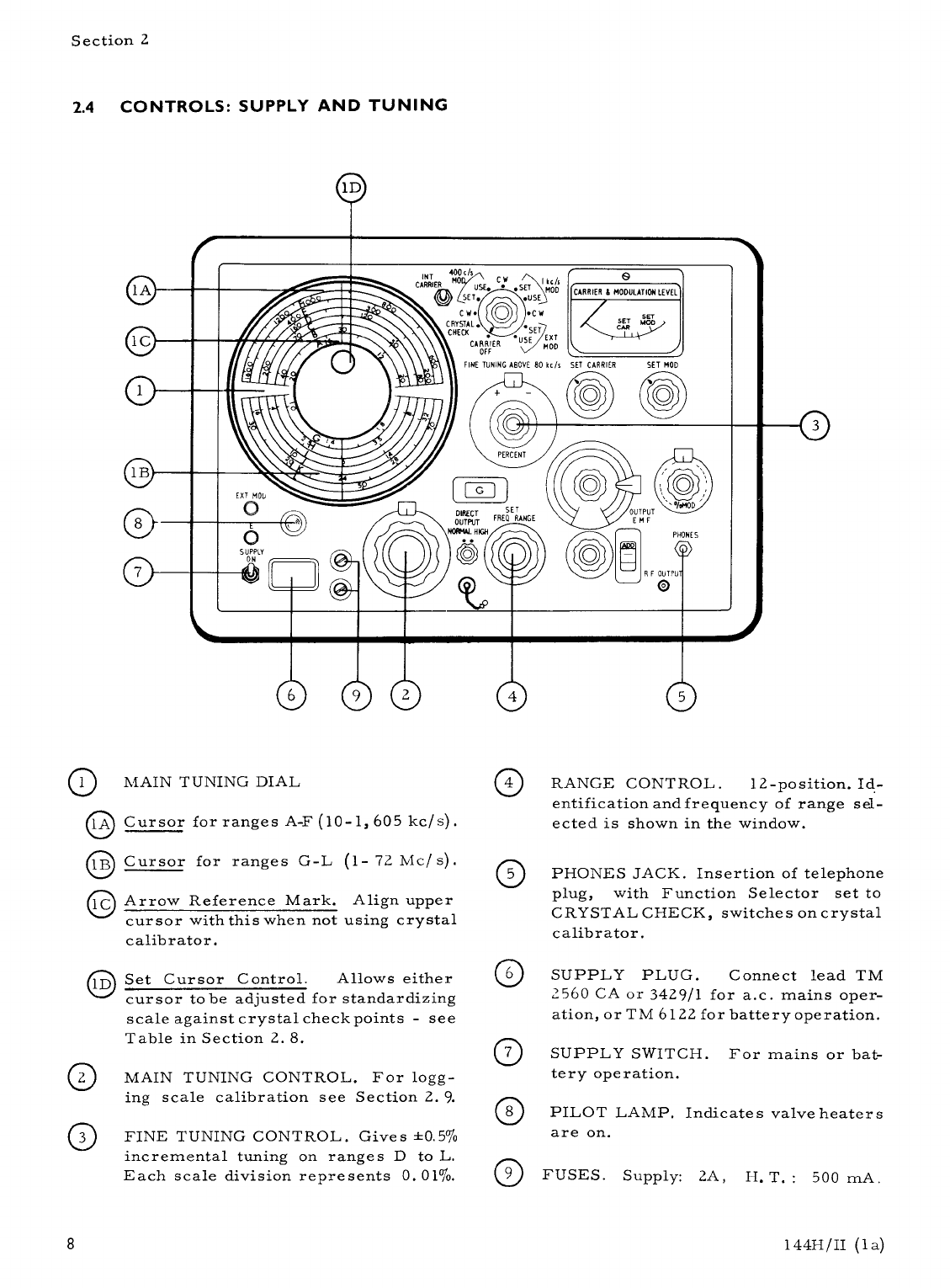
A large effective scale length
is provided on the main tuning dial whichhas
separate hand-calibrated scales for each
range. Its discrimination is such that a 2%
frequency change on any band occupies more
than a quarter of an inch of scale length.
Frequency accuracy is ±1%, but for greater
accuracy there is a built-in crystal calibrator
which gives at least 90 crystal check points
throughout the twelve ranges.
An 8:1 reduction drive from the main
tuning control enables easy and precise adj-
ustment to be made, and a linear logging
scale with 100 divisions attached to the main
tuning control facilitates interpolation be-
tween any of the main-scale divisions.
In
addition to the logging scale, a fine tuning
control is provided which is operative above
80 kc/ s and enables incremental frequency
adjustments to be made, with complete
freedom from backlash, up to ±0. 5% of the
frequency in use.
Modulation can be applied from an inter -
nal 400-c/ s to 1000-c/ s oscillator or from
an external source. In both cases, depth is
variable up to 80% over most of the frequency
range.
There are two r.f. signal outlets. One
supplies an output e.m.f. switchable between
2 and
2.
75 volts (monitored by the meter) at
very low impedance while the other supplies
a variable e.m.f. between 2 µV and 2 volts via
coarse and fine 50-ohm attenuators; the out-
put range may be extended down to 0.2 µV by
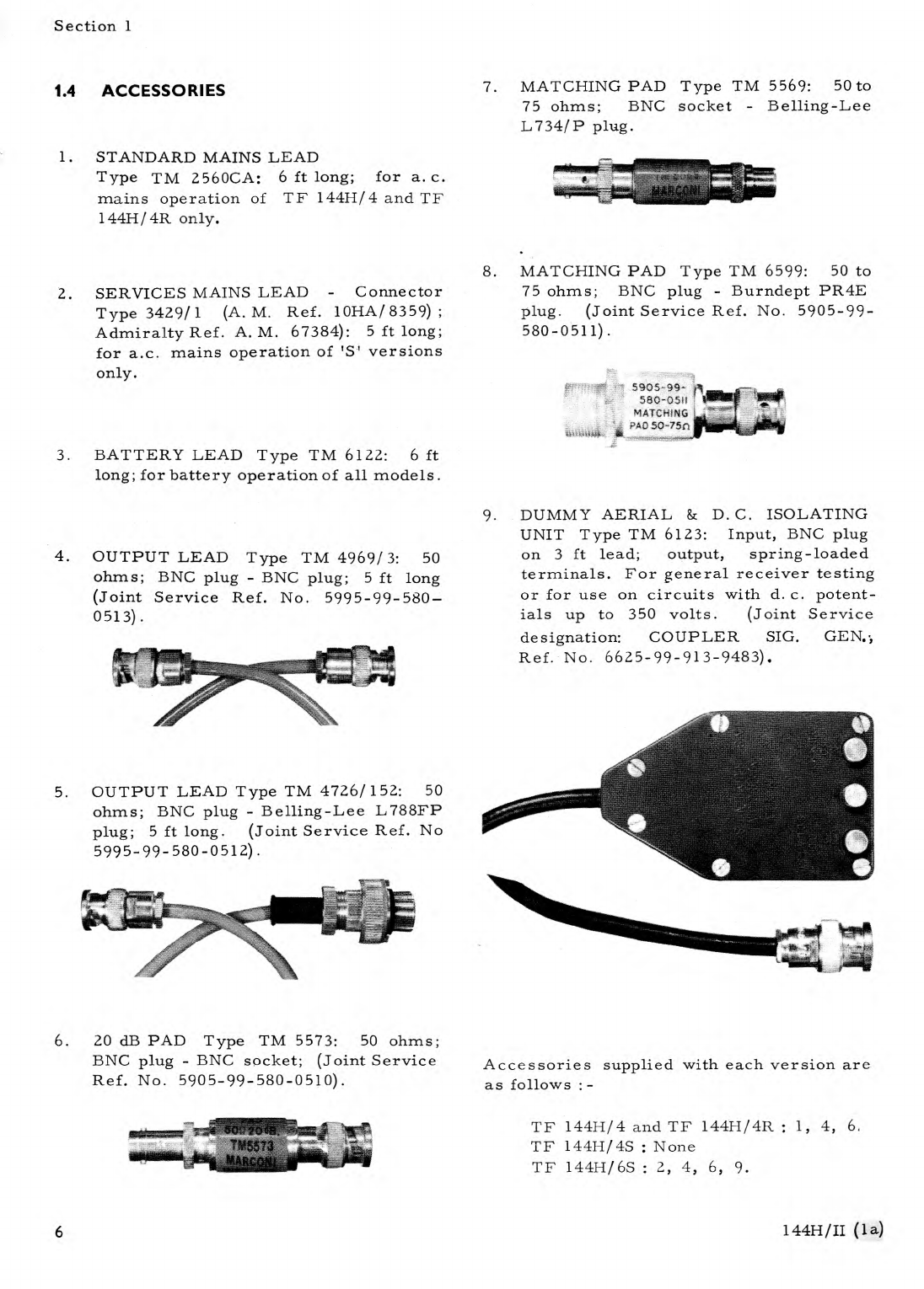
using the 20-dB Attenuator Pad accessory.
A system of automatic level control keeps
the carrier level constant throughout wide
frequency changes.
Designed for operation from either a. c.
mains or battery supplies the instrument is
available in forms suitable for bench or
rack mounting, as detailed below.
1.2 STANDARD AND SERVICES VERSIONS
TF 144H/4 and TF 144H/4R are the
standard bench- and rack-mounting models.
The versions with suffix 'S' are Services
types which are distinguished from the stan-
dard models by a sealed round meter, a
Plessey Mk. IV mains supply plug, and acc-
essories supplied.
Standard Models
TF 144H/4 : Bench mounting
TF 144H/4R : Rack mounting
Services Models
TF 144H/4S : Bench mounting.
No acces-
sories. Joint-Service Ref. No.
CT 452A.
TF 144H/6S : Bench mounting. With acces-
sories. Ref. No. CT 452A Set.
The accessories supplied and available
are described in Section 1.4.
144H/II (1)
3

Section 1
1.3 DATA SUMMARY
FREQUENCY
Range:
10 kc/ s to 72 Mc/ s, in 12 bands.
Main Tuning:
Straight-line frequency law on 8 bands.
Linear logging
scale on slow-motion drive divides the main scale into
nearly 400 divisions per band.
Calibration Accuracy:
±1%.
Fine Tuning:
Calibrated directly in % frequency change. Discrimin-
ation: 1 division = 0. 01%. Total cover: 1%. Accuracy:
±10% of scale reading for carrier frequencies below 16
Mc/ s; 15% of scale reading for higher frequencies. For
use at carrier frequencies above 80 kc/ s only.
Crystal Check:
400-kc/s and 2-Mc/ s crystals selected automatically by
band switch. Accuracy: ±0. 005%.
Stability:
±0. 002% in a ten-minute interval after warm-up.
OUTPUT
Impedance:
Calibrated Output:
Direct Output:
50 0 at calibrated output; v. s. w. r. better than 1.25:1.
2 p.V to 2 V e. m. f.
Low outputs down to 0.2
µV
using
20 dB Pad TM 5573.
Normal: approximately 2V.
High: 2. 75V into 750, directly monitored to an accuracy
of ±0. 5dB on ranges A to K or ±1. 0dB on range L.
Coarse Attenuator:
Eleven 10-dB steps.
Fine Attenuator:
Ten 1-dB steps; interpolation by carrier-level control
and meter.
Attenuator Accuracy:
Level Monitor:
Stray Radiation:
MODULATION
Internal A. M. :
Depth:
Within ±0.7 dB to
30 Mc/
s; within ±1 dB to 72 Mc/ s.
Protected-thermocouple voltmeter. Accuracy: ±0. 5 dB
absolute.
Negligible; permits full use of lowest output.
400 c/ s and 1 kc/ s, switch selected.
0 to 80% (dependent upon modulating frequency at low
carrier frequencies - see table under External A. M.);
monitored by carrier-level meter and calibrated control.
4
144H/II (la)

Section 1
1.3 DATA SUMMARY (continued)
External A. M. :
Spurious A. M. on C. W. :
Spurious F. M. on C. W. ;
Spurious F. M. on A. M. :
Accuracy of r. m. s. modulation: ±5% modulation (i. e.
6. 25% of full scale) at carrier frequencies where 80%
modulation is obtainable with low distortion - see table
under External A. M.
Minimum modulation frequency: 20 c/ s. The maximum
modulating frequency and depth which can be obtained at
low distortion, when the ratio of modulating frequency to
carrier frequency is small is, typically, as shown in the
following table : -
Carrier
Frequency
Max. Mod. Frequency
0-30%
30-50%
50-80%
10 kc/s
100 kc/ s
1 Mc/s
10 Mc/s
72 Mc/s
1 kc/ s
5 kc/ s
20 kc/ s
20 kc/ s
20 kc/s
400 c/ s
2 kc/ s
14 kc/s
17 kc/s
20 kc/s
200 c/ s
1 kc/ s
8 kc/ s
15 kc/s
20 kc/ s
Input requirements: approximately 6 volts into 25 1:2 for
80% modulation.
Less than 0.1% depth.
Deviation less than ±0.0001% of the carrier frequency.
At frequencies below 30 Mc/ s, deviation with 30% a.m.
is less than ±0.01% of the carrier frequency or ±100 c/ s,
whichever is the higher.
POWER SUPPLY
(A. C. Mains or external batteries)
A. C. Mains:
200 to 250 volts or 100 to 130 volts, adjustable at plug-
type supply-mains tapping panel. Frequency range, 40 to
100 c/ s; consumption, 80 watts.
Batteries:
L. T.: 6 volts, 2 amps.
H. T. : 240 volts, up to 50mA
depending on setting of controls.
DIMENSIONS & WEIGHT
Height
Width
Depth
Weight
(in bench case):
131 in
201 in
11 in
65 lb
(34 cm)
(52 cm)
(27.9 cm)
(29. 5 kg)
144H/II (la)
5

Section 2
2 OPERATION
2.1 INSTALLATION
Take off the transparent plastic cover, if
one is supplied with the instrument.
If the
cover is not completely removed when the
instrument is operated overheating may occur.
Position the instrument so that the ventilating
louvres at the rear and underneath are not
obstructed.
Unless otherwise specified, the instru-
ment is despatched with its mains input circuit
adjusted for immediate use on 240 volts within
the frequency range 40 to 100 c/ s.
It may
also be adjusted for operation from other a. c.
supply mains in the range 100 to 130 and 200
to 250 volts, or from 6-volt 1. t. and 240-volt
h. t. external batteries.
2.2 CONNECTIONS
For a. c. mains operation, first check or
alter the mains transformer tappings as shown
in Section 4.2
Connect the instrument to
the power socket by means of the mains lead
and plug in the r.f. lead to the R.F. OUTPUT
socket. These leads are normally stowed in
the two case handle recesses. A 20-dB
A.ttenuator Pad for use with the r. f. lead
when required, is clipped inside the right-
hand recess.
When the instrument is supplied for
Services use, an adaptor Type TM 6263 is
fitted into the front panel supply plug. This
provides the necessary circuit linkages, and
also an entry for the standard Plessey MkIV
Services power lead.
For battery operation, connect up the
special battery lead Type TM 6122 available
as an optional accessory
If the instrument
is to be used in a vehicle, use a separate 1. t.
battery, or alternatively, check that the
vehicle wiring employs a negative earth return
system. Since there is no Services equivalent
for the lead Type TM 6122 the Adaptor men-
tioned above should be removed to make way
for the McMurdo Type socket on the endof
the battery lead.
DO NOT CONNECT TO
+VE EARTHED LT SYSTEMS
Fig. 2.1 Battery Supply Lead
2.3 WARMING UP
The specified stability of 0.002% in a
10-minute period is not attained until a warm-
up period of about 3 hours has elapsed.
After switching on, and with the function
switch set to any position other than CAR-
RIER OFF, the initial drift will be of the
order of 0.01% of any selected frequency
per 10-minute period.
This higher order
of drift will of course diminish with time.
and you should therefore leave the instrument
switched on during periods of intermittent
use - preferably switched to the frequency
range required. When changing from one
frequency range to another, a period of 15
minutes or more should be allowed for max-
imum stability.
During the warm-up period however, you
can still be assured of a high order of accu-
racy provided that frequency checks are
made using the crystal calibrator. This
particularly applies in the case of battery
operation when it is undesirable to leave
the instrument switched on for long periods.
CAUTION
144H/II (la)
7

5905-99- tl
580-05Il
MATCHING
PAD
50-75n
Section 1
1.4 ACCESSORIES
1.
STANDARD MAINS LEAD
Type TM 2560CA: 6 ft long; for a. c.
mains operation of TF 14411/4 and TF
144H/4R only.
2.
SERVICES MAINS LEAD - Connector
Type 3429/1 (A.M. Ref. 10HA/ 8359) ;
Admiralty Ref. A. M. 67384): 5 ft long;
for a.c. mains operation of 'S' versions
only.
3.
BATTERY LEAD Type TM 6122: 6 ft
long; for battery operation of all models.
4.
OUTPUT LEAD Type TM 4969/ 3: 50
ohms; BNC plug - BNC plug; 5 ft long
(Joint Service Ref. No. 5995-99-580-
0513).
5.
OUTPUT LEAD Type TM 4726/152: 50
ohms; BNC plug - Belling-Lee L788FP
plug; 5 ft long. (Joint Service Ref. No
5995-99-580-0512).
6.
20 dB PAD Type TM 5573: 50 ohms;
BNC plug - BNC socket; (Joint Service
Ref. No. 5905-99-580-0510).
7.
MATCHING PAD Type TM 5569: 50 to
75 ohms; BNC socket - Belling-Lee
L734/P plug.
r
8.
MATCHING PAD Type TM 6599: 50 to
75 ohms; BNC plug - Burndept PR4E
plug. (Joint Service Ref. No. 5905-99-
580-0511).
9.
DUMMY AERIAL & D. C. ISOLATING
UNIT Type TM 6123: Input, BNC plug
on 3 ft lead; output, spring-loaded
terminals. For general receiver testing
or for use on circuits with d. c. potent-
ials up to 350 volts.
(Joint Service
designation: COUPLER SIG. GEN..,
Ref. No. 6625-99-913-9483).
Accessories supplied with each version are
as follows :-
TF 144H/4 and TF 144H/4R : 1, 4, 6,
TF 144H/4S : None
TF 144H/6S : 2, 4, 6,
9.
6
144H/II (la)

400
0
0s
I kas
MOD
•
USE
INT
CARRIER
CARRIER 8 MODULATION LEVEL
C
USE* • SET
SET.
C
CRYSTAL
CHECK
lA
0
I
•C
W
•
SET
EXT
MOD
CARRIER
USE
OFF
FINE TUNING ABOVE 80 kc/s SET CARRIER
SET MOD
PERCENT
G )
DIRECT
SET
OUTPUT FRES RANGE
NORMAL HIGH
•
•
0
R F OUTPU
0
OUTPUT
F
PHONES
O
Section 2
2.4 CONTROLS: SUPPLY AND TUNING
0
MAIN TUNING DIAL
Cursor for ranges A-F (10-1, 605 kc/s).
Cursor for ranges G-L (1- 72 Mc/ s).
Arrow Reference Mark. Align upper
cursor with this when not using crystal
calibrator.
RANGE CONTROL. 12 -po s ition. Id-
entification and frequency of range sel-
ected is shown in the window.
PHONES JACK. Insertion of telephone
plug, with Function Selector set to
CRYSTAL CHECK, switches on crystal
calibrator.
0
lA
O
0
0
Set Cursor Control.
Allows either
cursor to be adjusted for standardizing
scale against crystal check points - see
Table in Section 2. 8.
MAIN TUNING CONTROL. For logg-
ing scale calibration see Section 2. 9.
FINE TUNING CONTROL. Gives ±0.5%
incremental tuning on ranges D to L.
Each scale division represents 0.01%.
SUPPLY PLUG. Connect lead TM
2560 CA or 3429/1 for a.c. mains oper-
ation, or TM 6122 for battery operation.
SUPPLY SWITCH. For mains or bat-
tery operation.
PILOT LAMP. Indicates valve heaters
are on.
FUSES. Supply: 2A, H. T.: 500 mA.
8
144H/II (la)

PHONES
O
R.F OUTPUT
400 ch
USE.
.SET
SET.
C.W.
CRYSTAL.
CHECK
SET
USE EXT
CARRIER
OFF
MOD. \
s
_
FINE TUNING ABOVE 80 kc/s SET
I Itc/s
MOD.
•
USE
CARRIER
SET MOD
0
0
CARRIER 8 MODULATION LEVEL
0
0
0
0
0
10
EXT. MOD.
Section 2
2.5 CONTROLS: MODULATION AND OUTPUT
0
0
0
0
0
0
0
C.
W.
MONITORING. Adjust to SET
CARRIER mark, or to 0.5 dB marks
for attenuator interpolation.
MOD. MONITORING. Adjust to SET
MOD. mark with MODULATION SEL-
ECTOR at a SET position.
MODULATION SELECTOR. Carrier
Off position removes h. t. from r. f.
oscillator.
% MOD. Controls internal and ext—
ernal modulation.
EXT. MOD. TERMINALS.
25k0
impedance. About 6 volts input gives
80% modulation.
INTERRUPT CARRIER. For tempor-
arily switching off carrier without
affecting output impedance or stability.
COARSE ATTENUATOR. 11 steps of
10 dB.
Figures in window show : -
Black : dB relative to 1µV, to be
added to figure on dial.
Red or Green: Voltage range covered
by same-coloured scale on dial.
FINE ATTENUATOR. 10 steps of 1 dB.
Scales read :-
Black : dB relative to 1 p.V, to be
added to figure shown by Coarse
Attenuator.
Red or Green : Output voltage.
Multiply by factor depending on
range shown by C oar se Attenuator .
R. F. OUTPUT. Open-circuit e. m. f.
shown by attenuator controls. 50 ohms
source impedance. Connector: BNC
type UG291/U.
10
DIRECT OUTPUT.
2 volts output
variable only by SET CARRIER control
Connector: BNC type UG290/U.
11
DIRECT OUTPUT SWITCH.
Selects
direct output level; in the NORMAL pos-
ition 2 V, in the HIGH position 2. 75 V
With the switch at HIGH there is no out-
put from the R. F. OUTPUT socket.
144H/II (1)
9

INT.
CARRIER
400 c/s
USE.
SET.
CARRIER 8 MODULATION LEVEL
C WA
CRYSTAL.
CHECK
CARRIER
OFF
FINE TUNING ABOVE 80 kc/s SET CARRIER
SET MOD
*
SET
EXT
MOD
EXT MOD
0
0
SUPPLY
ON
1
11
)
OUTPUT
E.M F.
R.F OUTPUT
0
PHONES
Section 2
2.6 QUICK OPERATIONAL CHECK
O
The following sequence of operations
will enable you to get the feel of the controls
and to check that the r.f. oscillator, modul-
ation circuits, monitor and crystal calibrator
are working.
Switch to SUPPLY ON.
Turn the SET FREQ. RANGE switch
to F - 535 to 1605 kc/ s.
Adjust the main tuning control for an
indication of 1000 kc/ s against the
upper cursor.
Set the function selector to one of the
C. W. positions.
Bring the meter pointer to the SET
CARRIER mark by adjusting the SET
CARRIER control, and note that the
control is within, say, the middle
third of its travel.
Turn the function selector to 400 c/ s
MOD - SET.
Bring the meter pointer to the SET
MOD mark by adjusting the SET MOD
control.
Turn the function selector to 400 c/ s
MOD - USE.
Rotate the % MOD control and check
that the modulation depth readings on
the control scale and the meter agree.
Turn the function selector to CRYSTAL
CHECK.
Plug headphones into the PHONES jack
and check that a beat note can be heard
as the main tuning dial is rocked through
one or two divisions about the 1000 kc/s
mark.
O
O
O
O
O
O
O
O
O
O
10
144H / II (1)

DIRECT
SET
OUTPUT FREQ. RANGE
NORMAL HIGH
PHONES
O
R F OUTPUT
O
Ni
400 cis
I
CARRIER
fh
SET.
C M.
CRYSTAL •
CHECK
CARRIER
OFF
FINE TUNING ABOVE 80 kc/s
CARRIER i MODULATION LEVEL
SET CARRIER
SET MOD
ET
.USE
.0 w.
*
SET
USE /EXT
MOD
PERCENT
O
3
11
Section 2
2.7 C.W. OPERATION
Check the mechanical zero setting of
the meter and adjust if necessary.
Switch to SUPPLY ON and allow time
to warm up.
Turn the SET FREQ RANGE control to
the required range.
Bring the upper cursor line to the ar-
row mark by means of the SET CURSOR
control. Adjust the main tuning cont-
rol to bring the main dial reading to
the approximate frequency required.
Turn the FINE TUNING control to 0.
For maximum accuracy switch to
CRYSTAL CHECK and plug headphones
into the PHONES jack.
Readjust the
main tuning control for zero beat at the
nearest crystal check point (see Section
2. 8 for check point frequencies) and
reset the cursor to correct the dial
reading.
Tune to the exact required output fre-
quency by adjusting the main dial to
the nearest calibrated mark and inter-
polating by means of the logging scale
on the main tuning control (see Section
2.
9
for logging scale calibration).
Switch to C. W. and adjust the SET
CARRIER control to bring the meter
pointer to the SET CARRIER mark.
Adjust the OUTPUT E. M. F. controls
for the required output voltage.
NOTE: Watch the meter when making
large frequency changes - it may be
necessary to readjust the SET CARRIER
control.
O
O
O
O
O
O
O
O
O
O
10
11
14411/11 (1)

Section 2
2.8 USE OF CRYSTAL CALIBRATOR
To use the crystal calibrator, plug head-
phones into the PHONES jack and switch to
CRYSTAL CHECK. Adjust the main tuning
dial to obtain zero beat at the nearest check
point to the wanted frequency. Then use the
SET CURSOR control to align the cursor with
the check point frequency indication on the
dial.
Crystal check point frequencies occur as
follows : -
Ranges A to D at submultiples of 400 kc/ s,
Ranges E and F at submultiples of 2 Mc/ s,
Ranges G and H at multiples of 400 kc/ s,
Ranges I to L at multiples of 2 Mc/ s.
The actual frequencies are tabulated below.
TABLE 2.1
CRYSTAL CHECK POINT FREQUENCIES
Range A
Range B
Range C
Range D
Range E
Range F
10-20
20-40
40-80
80-200
200-535
535-1605
kc/ s
kc/ s
kc/ s kc/ s
kc/ s kc/ s
10
20.00
40.00
80.00
200.00
666.66
10.26
21.05
44.44
100.00
222.22
1000.00
10.53
22.22
50.00
133.33
250.00
1333.00
10.81
23.53
57.14
200.00
285.71
1500.00
11.11
25.00
66.66
333.33
11.43
26.66
80.00
400.00
11.76
28.57
500.00
12.12
30.77
12.5
33.33
12.9
36.36
13.33
40.00
13.79
14.29
14.81
15.38
16.00
16.66
17.39
18.18
19.05
20.00
Range G
Range H
Range I
Range J
Range K
Range L
1-2
2-4
4-8
8-16
16-32
30-72
Mc/ s
Mc/ s Mc/ s
Mc/ s
Mc/ s
Mc/ s
Check points every
400 kc/ s
Check points every 2 Mc/ s
12
144H/II
(la)

0
70
4
5
"1
4
04
2
•
"
2
RANGE F
I
I
I
•
ffirr
1
•
I.
1 ,
-.nit- •
: 17
—
r
•
r-
Section 2
2.9 TUNING CONTROL LOGGING SCALE
RANGE A : 30 c/s per division
RANGE B : 60 c/ s per division
RANGE C : 120 c/s per division
4Emmm
gam mg
ME
EM
ME
====
MESHES
=
= =
SOMINEMMEMMINEM
M-6
c
/s
p
er
div
is
io
n
RANGE D
500
400
300
80
100
120
140
160
180
200
Frequency kc/ s
0
T4 1.3
'5
"
1
1.
to
•
0.9
-%
•
0.7
RANGE E
220
260
300
340
380
420
460
500
Frequency kc/ s
600
800
1000
1200
1400
Frequency kc/ s
RANGE G : 3 kc/s per division
RANGE H : 6 kc/s per division
RANGE I : 12 kc/ s per division
RANGE J 24 kc/ s per division
RANGE K : 48 kc/ a per division
kc
/s
p
e
r
div
is
io
n
150
140
130
120
110
II 1
14
:::!
!!111111t
m
lr
RANGE
ME M
MENMME:== r
1:
.
6:12
30
40
50
60
Frequency Mc/ s
144H/II (1)
13

DIRECT
SET
OUTPUT FREQ. RANGE
NORMAL
HIGH
•
•
PHONES
O
R.F OUTPUT
0
CARRIER 8
ADULATION LEVEL
INTERNAL
EXTERNAL
2.10 A.M. OPERATION
400c/
INT
inn
CARRIER
CM.
CRYSTAL
•
CHECK
CARRIER
OFF
SET
•
USE
EXT
MOD
FINE TUNING ABOVE 80 kc/s SET CARRIER
SET MOD
PERCENT
EXT MOD
SUPPLY
014
Section 2
Switch on, tune, and set output as for
C. W. (see Section 2. 7).
Switch to 400 c/ s MOD-SET or 1 kc/s
MOD-SET and adjust the SET MOD
control to bring the meter pointer from
the SET CARRIER mark to the SET
MOD* mark.
Switch to the adjacent USE position and
set the % MOD control to indicate the
required percentage modulation on
its dial.
Switch on, tune, and set output as for
C. W. (see Section 2. 7).
Connect the external modulating source
to the EXT MOD and E terminals
(about 6 volts for 80% modulation).
Switch to EXT MOD -SET and adjust the
SET MOD control to bring the meter
pointer from the SET CARRIER mark
to the SET MOD* mark.
Switch to EXT MOD-USE and set the
% MOD control to indicate the required
percentage modulation on its dial.
O
O
O
O
O
O
O
O
14
Except at low carrier and high modulation frequencies. The maximum depth for'low-
distortion modulation is limited when the modulation frequency exceeds a certain percent-
age of the carrier frequency (about 2% at 10 kc/ s carrier to about 0.1% at 10 Mc/ s). The
maximum modulation frequencies for different carrier frequencies and modulation depths
are shown in the table in Data Summary - Modulation, Section 1.3. When using a combin-
ation of carrier and modulation frequency that puts a limitation on the modulation depth,
the 50% or 30% mark on the meter is used instead of the SET MOD mark.
For example : at 10 kc/ s carrier, 400 c/ s modulation, set to the 50% mark;
at 10 kc/ s carrier, 1000 c/ s modulation, set to the 30% mark;
at 1 Mc/ s carrier, 14 kc/s modulation, set to the 50I0 mark.
144H/II (1)

Section 2
2.11 R.F. OUTPUT ARRANGEMENTS
The R. F. OUTPUT circuit of the Signal
Generator should be regarded as a zero-
impedance voltage source in series with a
re si stance of 50 ohms.
This is shown in
Fig. 2.8 where :
E is the indicated source e. m. f. ,
Ro is the source resistance,
Rt. is the external load resistance
VL, the voltage developed across the load, is
given by
Ri
V
L
-= E. Ro + RE
Note: if the load is not predominantly resist-
ive the reactive component must betaken into
account and ±jX added to RL
Table 2.2 shows the conversion factors for
obtaining the load voltage from the indicated
e.m.f. at different load impedances.
When using a correctly matched, i. e.
50-ohm, output lead its output end can be
regarded as an extension to the output socket
on the Generator and wide variations in load
impedance do not seriously affect the calcul-
ated load voltage obtained from Table 2.2.
Standing waves produced by the mismatched
load can, for most purposes, be ignored.
TABLE 2.2
LOAD
ohms
To find load voltage:
Multiply
or
Subtract
E. M. F. by
dB
10
0.167
15.5
20
0.286
10.9
30
0.375
8.5
40
0.445
7.0
50
0.50
6.0
60
0.55
5.2
70
0.58
4.7
75
0.60
4.4
80
0.62
4.2
90
0.64
3.8
100
0.67
3.5
120
0.71
3.0
150
0.75
2.5
200
0.80
1.9
300
0.86
1.3
500
0.91
0.8
600
0.92
0.7
800
0.94
0.5
1000
0.95
0.4
2000
0.98
0.2
4000
0.99
0.1
OUTPUTS INTO 50-OHM LOADS
The voltage developed across a 50-ohm
load is equal to half the e. m. f. indicated on
the voltage scales of the Generator output
controls, or 6 dB less than d13µV indication
Fig. 2.8
Equivalent
output circuit
For greatest accuracy - if the additional
attenuation can be tolerated - use the 20-dB
Attenuator Pad Type TM 5573 between serious-
ly mismatched loads and the output lead.
This ensures that the lead is correctly term-
inated, and also attenuates any extraneous
noise induced in the lead.
Fig. 2.9
' 7
50-ohm load
E- 6d8
144H/II (1)
15

Series resistor
Equivalent
in circuit
circuit
Fig. 2.10 High-impedance matching
and the voltage across the load, VI , is given
by
El
Vi.
=
7
Section 2
MATCHING TO HIGH IMPEDANCE LOADS
To present a load that is greater than
50 ohms with a signal derived from a matched
source, a resistor Rs is added in series with
the Generator output.
The value of Rs is
given by the difference between the load and
Generator impedances, that is,
Rs = Ri - Ro
Parallel resistor
in circuit
Equivalent
circuit
Fig. 2.11 Low-impedance matching
Rs
The effective source e. m. f. , El, is
now different and is given by
Rp
El
=
E
Rp+Ro
L
The voltage across the load, Vi, is given
by
E
Vi =
2
For the special case of a 75-ohm load a
Matching Pad, Type TM 5569 or TM 6599, is
available as an accessory and consists basic-
ally of a 25-ohm resistor with coaxial con -
nectors for insertion in series with the output
lead.
MATCHING TO BALANCED LOADS
Equipment whose input circuit is in the
form of a balanced winding can be fed from
the Generator by using two series resistors
as shown in Fig. 2.13. This method makes
use of the auto-transformer effect of the
centre-tapped windings and is not suitable
for resistive balanced loads.
RI
Fig, 2.12 Balanced load matching
MATCHING TO LOW-IMPEDANCE LOADS
To present a load that is less than 50
ohms with a signal derived from a matched
source, a resistor Rp is added in parallel
with the Generator output. The value of Rp
is given by
R oR
Rp =
Ro - R
The values of R1 (for use in the live
lead) and R2 (for the earth lead) are given
by
R
Zi
2 - ---2
ZL
=
and RI
2
- 50
16
144H/II (1)

0 I
I-.
EMF
Ro
4On
DC ISOLATOR
SOn
100p
Er
o
F
DUMMY
AERIAL
EARTH --I
Section 2
2.12 USE OF 20-dB ATTENUATOR PAD
It is recommended - provided that the
reduced output e.m.f. can be tolerated - that
the 20-dB Attenuator Pad TM 5573 should be
permanently connected to the output end of
the r. f. lead. Terminated in this way, the
extraneous noise pick-up in the lead is atten-
uated by a factor of ten before being applied
- together with the signal - across the load.
This arrangement is particularly advantage-
ous when making signal-to-noise tests on
receivers at low voltage level.
With the Pad in circuit, the possibility
of errors inapparent e.m.f. or output imped-
ance, due to the presence of standing waves
at the higher frequencies, is avoided since it
is now impossible to seriously mismatch the
r.f. lead. In fact, variations in load imped-
ance between zero and infinity cause the
effective value to depart from the correct
value by as little as 1 ohm.
Ro
20dB
SOO
PAD
Pad in
Equivalent
circuit
circuit
Fig. 2.13 Effect of 20-dB Pad
The Pad reduces the effective source
e.m.f. by a factor of 10: therefore, the
figures for load voltage obtained from Table
2.2 must be divided by 10 or reduced by
20 dB.
The load voltage, VI, is given by
VI = E
RL
10
Ro+ RL
When matching to loads other than 50
ohms, the matching resistor must be inserted
on the output side of the Pad; the expressions
given in Section 2.11 then become : -
E
For series matching, VI =
20
For parallel matching,
Rp
Rp +Ro
2.13 USE OF DUMMY AERIAL
AND D.C. ISOLATOR
Fig. 2.14 Generator output using TM 6123
To use this dual-purpose unit as a dummy
aerial, connect the EMF/ 10 and E terminals
to the receiver under test. The unit then
simulates the impedance of a typical aerial
for broadcast receivers in the 1.f., m.f. and
h. f. bands, and provides an open-circuit
e.m.f. of one-tenth of that indicated by the
Generator.
To use it as a 350-volt d. c. isolator
connect the EMF/2 and E terminals to the
equipment under test.
This allows the
Generator output to be applied to circuits
having a standing d. c. potential up to 350
volts.
The open-circuit e. m. f. is half of
that indicated by the Generator.
2.14 DIRECT OUTPUT
Two r. f. levels are available at the
DIRECT OUTPUT socket; with the DIRECT
OUTPUT switch at NORMAL an e.m.f. of
2 V is provided and with the switch at HIGH
an output, which is pre set during manufacture
at 2.75 V (100 mW into a 75 C2 load), is avail-
able. The source impedance with the switch
in either position is virtually zero.
As with the R. F. OUTPUT the stated
level depends on the SET CARRIER control
having been adjusted to bring the pointer of
the CARRIER AND MODULATION LEVEL
;
:)
VI
E
1
=
E
20
20
144H/II (1)
17

Section 2
meter to the SET CARRIER mark, but you
will notice that adjustment to the SET CAR-
RIER control is not usually necessary when
switching from NORMAL to HIGH.
The minim .= load impedance which may
be presented to the DIRECT OUTPUT when
switched to NORMAL is 200 0 and when swit-
ched to HIGH is 501
-
2. If, for any reason, the
impedance of the load is lower than these fig-
ures add a series resistor between the DIR-
ECT OUTPUT and the cable to bring the ef-
fective impedance seen by the generator up
to the minimum value.
NOTE: At high frequencies the connecting
cable may amount to a quarter wave-
length and then, if terminated with a
high impedance this will appear as a
very low impedance to the Signal Gen-
erator.
The R.F. OUTPUT is disconnected when
the DIRECT OUTPUT is switched to HIGH.
18
144H/II (1)
This manual suits for next models
2
Table of contents
Other Marconi Inverter manuals