-3-
ASSE BLY INSTRUCTIONS
INTRODUCTION
Assembly of your SM-9600K Function Generator Kit
will prove to be an exciting project and give much
satisfaction and personal achievement. If you have
experience in soldering and wiring technique, you
should have no problem with the assembly of this kit.
Care must be given to identifying the proper
components and in good soldering habits. Above all,
take your time and follow the easy step-by-step
instructions. Remember, “an ounce of prevention is
worth a pound of cure”. Avoid making mistakes and
no problems will occur.
PARTS VERIFICATION
Before beginning the assembly process, familiarize
yourself with the components and this instruction
book. Verify that all parts are present. This is best
done by checking off each item against the parts list.
Care must be taken when handling the chip resistors
and capacitors. They are very small and are easily
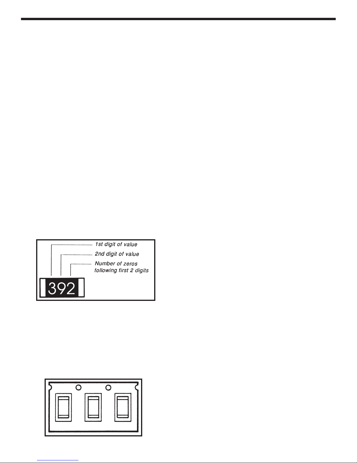
lost. Chip resistors are marked with their component
value. The first two digits are the first two digits of the
resistance in ohms. The last digit gives the number
of zeros following the first two digits. The resistor
shown below is therefore 3,900Ω.
The values of the chip capacitors are not marked
on the component. To avoid mixing these parts
up, they should not be taken out of their
packages until just before they are soldered to
the PC board. The 0.01µF capacitors are packaged
three to a pack, as shown below. The 0.1µF
capacitors are in similar packaging with two to a
pack. The 820pF capacitor is the unmarked
component packaged one to a pack.
SAFETY PROCEDURES
• Wear eye protection when soldering.
•
Locate soldering iron in an area where you do not
have to go around it or reach over it.
•Do not hold solder in your mouth. Solder
contains lead and is a toxic substance. Wash your
hands thoroughly after handling solder.
• Be sure that there is adequate ventilation present.
SOLDERING TIPS
The most important factor in assembling your new
SM-9600K Function Generator Kit is good soldering
techniques. Using the proper soldering iron is of
prime importance. A small pencil type iron of 10-15
watts is recommended. A sharply pointed tip is
essential when soldering surface mount
components. The tip of the iron should be kept clean
and well-tinned at all times. Many areas on the
printed circuit board are close together and care
must be given not to form solder shorts. Solder
shorts may occur if you accidentally touch an
adjacent foil, particularly a previously soldered
connection, using too much solder, or dragging the
iron across adjacent foils. If a solder short occurs,
remove it with your hot iron. Use only rosin core
solder of 63/37 or 60/40 alloy.
Before soldering, the SM-9600K board should be
taped to the workbench to keep it from moving when
touched with the soldering iron. For a good soldering
job, the areas being soldered must be heated
sufficiently so that the solder flows freely. When
soldering surface mount resistors and capacitors, the
following procedure may be used:
1. Using tweezers, place the surface mount
component on the PC board pads and secure in
place with tape.
2. Apply a small amount of solder to the soldering
iron tip. This allows the heat to leave the iron and
flow onto the foil.
3. Place the iron in contact with the PC board foil.
Apply a small amount of solder simultaneously to
the foil and the component and allow them to
melt the solder.
4. Remove the iron and allow the solder to cool.
The solder should have flowed freely and not
lump up around the component.