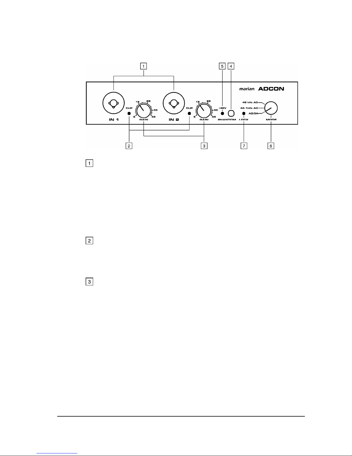
“Phantom” Switch
Using this switch you can power on/off the phantom power
supply for the inputs on the front side. The activity of the
phantom power supply is indicated by the “+48V” LED
described in [5].
“+48V” LED
The “+48V” indicates that the phantom power supply for the
inputs on the front side is powered on.
“Mode” Switch
The “Mode” switch changes the operation mode of your
ADCON:
In the “48 kHz AD” position the ADCON works as clock
master. The internal clock operates using 48 kHz. In this
switch position the device exclusively converts the analog
input signals into an ADAT output signal.
In “44.1 kHz AD” position the ADCON also works as clock
master using only 44.1 kHz. In this case the analog input
signals are also converted into an ADAT output signal.
In “AD/DA” position, the ADCON synchronizes to the sampling
rate of the existing ADAT signal and works as clock slave.
Here it converts the incoming ADAT signal into analog output
signals and the analog input signals into ADAT output signal.
“Lock” LED
This LED illuminates if a valid signal exists in switch position
“AD/DA” at the ADAT input and the ADCON synchronizes to it.
2.1.1. Using Microphones for Ports on the Front Side
If you would like to use microphones for the ports on the front
side, please connect them only when the ADCON is switched off.
Otherwise this may lead to interfering impulses, which could
cause damage to the electronics of the ADCON, loud speakers or
other devices!
Please note that the phantom power supply is only powered on, if
microphones are connected which require a phantom power
supply of +48 V!
4