AXIOMATIC UMAX030440 User manual

USER MANUAL UMAX030440
Version 2B
4 Universal Signal Inputs, 5V/8V Voltage Reference,
CAN Controller with SAE J1939
USER MANUAL
P/N: AX030440

UMAX030440 Version 2B 2-51
ACRONYMS
ACK Positive Acknowledgement
CSR CAN Status Report
DM Diagnostic Message (from SAE J1939 standard)
DTC Diagnostic Trouble Code
FMI Failure Mode Identifier
OC Occurrence Count
EA Axiomatic Electronic Assistant (Service Tool for Axiomatic ECUs)
ECU Electronic Control Unit (from SAE J1939 standard)
MAP Memory Access Protocol
NAK Negative Acknowledgement
PDU1 A format for messages that are to be sent to a destination address,
either specific or global
PDU2 A format used to send information that has been labeled using the Group Extension
technique and does not contain a destination address.
PGN Parameter Group Number (from SAE J1939 standard)
PropB Message that uses a Proprietary B PGN
SPN Suspect Parameter Number (from SAE J1939 standard)

UMAX030440 Version 2B 3-51
TABLE OF CONTENTS
1.1. INTRODUCTION TO AX030440 FEATURES.................................................................................................................. 4
1.2. J1939 NETWORK –DIAGNOSTIC BROADCAST ........................................................................................................... 4
1.3. UNIVERSAL INPUT..................................................................................................................................................... 5
1.3.1. Control Sources............................................................................................................................................................5
1.3.2. Universal Input Type ....................................................................................................................................................5
1.3.3. Universal Input Range.................................................................................................................................................. 5
1.3.4. Universal Input Analog Filter........................................................................................................................................6
1.3.5. Universal Input Error and Range..................................................................................................................................6
1.3.6. Universal Input Digital Input Parameters.....................................................................................................................6
1.3.7. Universal Input Frequency/PWM Parameters .............................................................................................................7
1.3.8. Universal Input Data Filter ...........................................................................................................................................8
1.3.9. Universal Input Diagnostic Parameters........................................................................................................................8
1.4. MISCELLANEOUS...................................................................................................................................................... 8
1.5. DIAGNOSTICS........................................................................................................................................................... 9
1.6. CONSTANT DATA.................................................................................................................................................... 11
1.7. MATH FUNCTION BLOCK......................................................................................................................................... 11
1.8. PROGRAMMABLE LOGIC FUNCTION BLOCK ............................................................................................................. 12
1.9. LOOKUP TABLE FUNCTION BLOCK.......................................................................................................................... 13
1.10. CONDITIONAL BLOCK ........................................................................................................................................... 14
1.11. SET /RESET LATCH FUNCTION BLOCK.................................................................................................................. 15
1.12. CAN TRANSMIT FUNCTION BLOCK........................................................................................................................ 15
1.13. CAN RECEIVE FUNCTION BLOCK.......................................................................................................................... 16
2. OVERVIEW OF J1939 FEATURES....................................................................................................................... 18
2.1. INTRODUCTION TO SUPPORTED MESSAGES............................................................................................................. 18
2.2. J1939 NAME,ADDRESS AND SOFTWARE ID............................................................................................................ 19
2.2.1. J1939 Name................................................................................................................................................................19
2.2.2. ECU Address ...............................................................................................................................................................19
2.2.3. Software Identifier .....................................................................................................................................................20
3. ECU SETPOINTS ACCESSED WITH ELECTRONIC ASSISTANT...................................................................... 21
3.1. J1939 NETWORK SETPOINTS.................................................................................................................................. 21
3.2. UNIVERSAL INPUT SETPOINTS................................................................................................................................. 21
3.3. MISCELLANEOUS SETPOINTS .................................................................................................................................. 22
3.4. DIAGNOSTIC SETPOINTS ......................................................................................................................................... 23
3.5. CONSTANT DATA LIST SETPOINTS .......................................................................................................................... 24
3.6. MATH FUNCTIONAL BLOCK SETPOINTS ................................................................................................................... 24
3.7. PROGRAMMABLE LOGIC BLOCK SETPOINTS............................................................................................................ 26
3.8. LOOKUP TABLE SETPOINTS .................................................................................................................................... 28
3.9. CONDITIONAL BLOCK SETPOINTS............................................................................................................................ 29
3.10. SET-RESET LATCH BLOCK ................................................................................................................................... 30
3.11. CAN TRANSMIT SETPOINTS.................................................................................................................................. 31
3.12. CAN RECEIVE SETPOINTS.................................................................................................................................... 33
3.13. 5V TO 8V REFERENCE SWITCH ............................................................................................................................. 34
4. REFLASHING OVER CAN WITH ELECTRONIC ASSISTANT BOOTLOADER ................................................. 35
4.1. PREREQUISITES...................................................................................................................................................... 35
4.2. RE-FLASHING PROCEDURE ..................................................................................................................................... 35
5. INSTALLATION INSTRUCTIONS ......................................................................................................................... 40
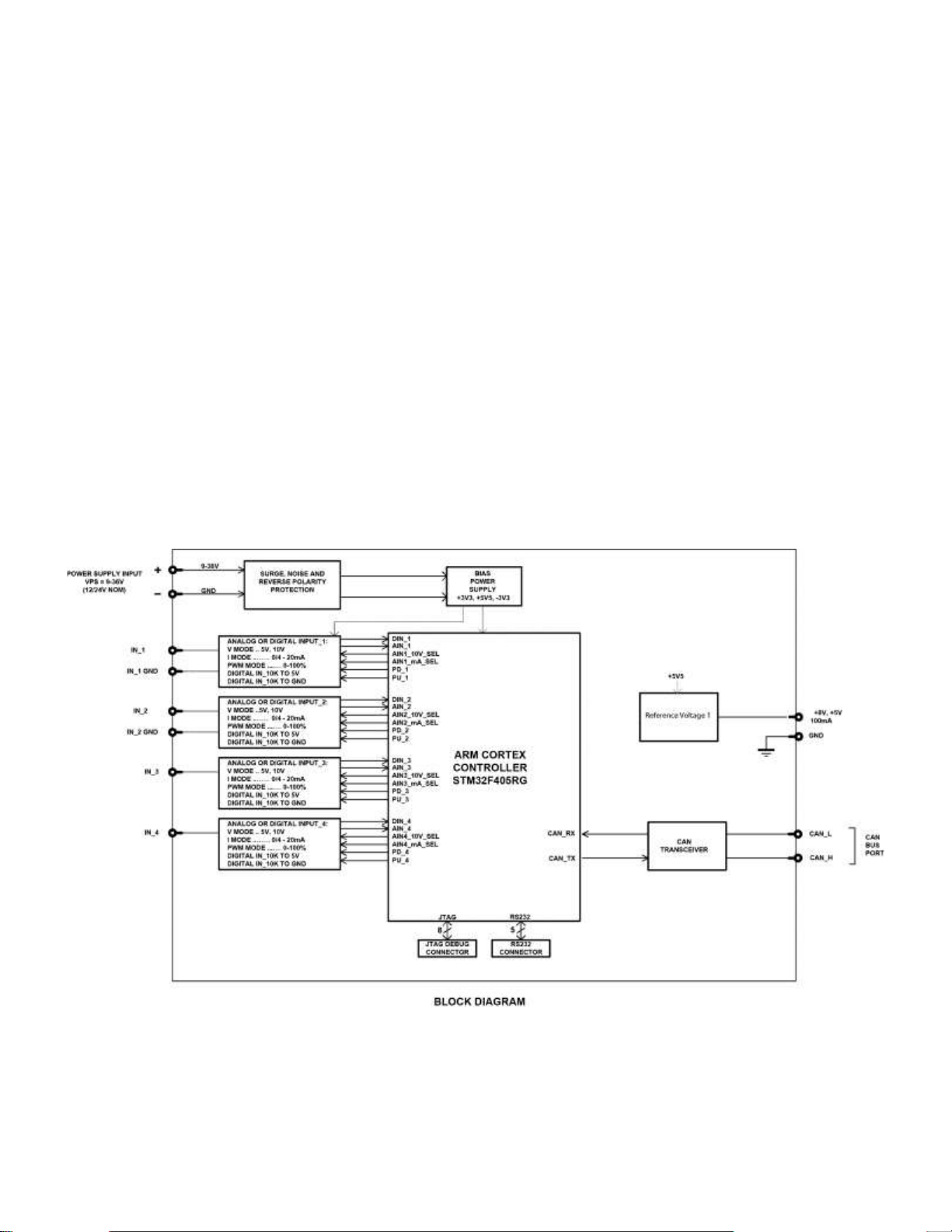
6. TECHNICAL SPECIFICATIONS............................................................................................................................ 41
Reverse polarity protection up to -100V..................................................................................................................................41
User selectable .........................................................................................................................................................................41
+5V/+8V, 100 mA, 2% reference voltage output......................................................................................................................41
7. VERSION HISTORY............................................................................................................................................... 43

UMAX030440 Version 2B 4-51
GENERAL INFORMATION
1.1. Introduction to AX030440 Features
The 4UIN-8VREF-2CAN electronic control unit (ECU) is designed to provide a simple interface for
Universal Inputs over a J1939 CAN Network, to be used in a power generator set or industrial
environment. The hardware supports 4 Universal Inputs. The universal inputs accept voltage,
current, resistance, frequency, PWM duty cycle, and discrete voltage levels. A +8V or +5V
reference voltage output can be used to power external sensors/equipment. The voltage reference
level can be configured using EA.
The ECU has been designed to allow the maximum amount of versatility to optimize the
performance of the machine. Numerous configurable variables, called setpoints, have been
provided which are accessible using Axiomatic Technologies’ Electronic Assistant. Information
about the setpoint defaults and ranges is outlined in Section 3. The EA communicates with the
controller over J1939 CAN bus and uses Memory Access Protocol (MAP) to read/write each
setpoint. Once the ECU has been setup as desired, the setpoints can be saved to a file, and
flashed into other controllers using EA.
The ECU is an arbitrary address capable ECU, which can perform dynamic address allocation at
the run time. It also provides all necessary network support required by the J1939 standard.
1.2. J1939 Network –Diagnostic Broadcast
Diagnostic messages are triggered by the internal function blocks and then broadcasted on the
CAN bus network. However, in some applications this broadcast may not be required and so the

UMAX030440 Version 2B 5-51
user has the option to disable or enable this feature. Section 1.4 and 3.3 shows the configuration
of this feature by using the Electronic Assistant tool.
1.3. Universal Input
1.3.1. Control Sources
The different function blocks in the ECU are commanded by a set of Control Sources. This section
lists the different available control sources for these functions and their respective ranges.
Value
Meaning
Source Range
0
Control Not Used
[0]
1
Universal Input
[1…4]
2
CAN Receive
[1…10]
3
Constant Data
[1…15]
4
Math Block
[1…5]
5
Programmable Logic Block
[1…3]
6
Lookup Table
[1…10]
7
Conditional Logic Block
[1…10]
8
Set-Reset Latch
[1…5]
Table 1: Control Sources
While these sources are available for all functional blocks, it is not recommended to use Constant
Data as a source in the Set-Reset Latch block.
1.3.2. Universal Input Type
The Input Type parameter allows the user to select how the controller responds to the behaviour
of the input. Table 2 shows the different options for each input.
Value
Meaning
0
Input Disabled
1
Voltage Input
2
Current Input
3
Digital Input
4
Frequency Input
5
PWM Input
6
Resistive Input
Table 2: Universal Input Types
1.3.3. Universal Input Range
The Input Range parameter is used to specify the expected range of Voltage or Current inputs. It
is disabled for other input types. Table 3 shows the options available for this parameter when a
Voltage Input is selected, and Table 4 show the options for a Current Input.
Value
Meaning
0
0 - 5V Analog Input

UMAX030440 Version 2B 6-51
1
0 - 10V Analog Input
Table 3: Voltage Input Ranges
Value
Meaning
0
0 - 20mA Analog Input
1
4 - 20mA Analog Input
Table 4: Current Input Ranges
Also, the Pull Up/Down parameter can be set when the Input Type is set to Voltage Input and
Input Range is set to 0-5V Analog Input. It allows the ECU to work in two modes for this input
range: 5V in High Impedance and 5V with 10kOhm Impedance.
Note: It is only possible to set the pull-down resistor either high or low if the Input Type is set to
Input Voltage. If 10kOhm pull-down is disabled, the ECU will run in 5V in High Impedance mode.
Setting the pull-up resistor option is not available for this input type.
1.3.4. Universal Input Analog Filter
The Analog Filter parameter is only applicable when a voltage or a current type is being measured.
In these cases, the ADC will automatically filter as per Table 5, and is set for 50Hz noise rejection
by default.
Value
Meaning
0
Input Filter Off
1
Filter 50Hz
2
Filter 60Hz
3
Filter 50Hz and 60Hz
Table 5: Analog Filter
1.3.5. Universal Input Error and Range
Each Input can have different Input Ranges which can be configured. The Range Min and Range
Max parameters are used to set the range for the input. The Error Min and Error Max parameters
are used to set when the accompanying diagnostic message will be triggered.
1.3.6. Universal Input Digital Input Parameters
If the Input is configured as a Digital Input, the following setpoints become available to help
configure the input.
The Pull Up/Down parameter is used to change the configuration of internal resistors with the
following options.
Value
Meaning
0
No Pull
1
Pull Up Network
2
Pull Down Network
Table 6: Digital Input Pull Up/Down
The Logic Type parameter is used to determine how the input is received when configured as a
Digital Input.
Value
Meaning

UMAX030440 Version 2B 7-51
0
Input Not Implemented
1
Normal Logic
2
Inverse Logic
3
Latched Logic
4
Inverse Latched Logic
Table 7: Digital Input Logic Type
By default, the Normal Logic type is used for the digital input.
In Normal Logic mode, the input state is 1 in case the input signal is interpreted as an ON-signal.
The input state turns 0 if the input signal is interpreted as an OFF-signal.
For the Inverse Logic type, the opposite behavior applies. If the input signal is ON, the state turns 0
and if the input signal is OFF, the state turns 1.
Setting the Input to Latched Logic, the input state is toggled between 1 and 0 every time the input
signal of the respective digital input changes from OFF to ON.
In Inverse Latched Logic mode, the opposite behaviour applies. The input state toggles between 1
and 0 every time the input signal changes from ON to OFF.
The Digital Input Debounce Time parameter is a useful parameter in cases where the digital input
signal coming into the controller is noisy. Figure 1 shows how the Debounce Time helps detect a
correct input signal.
Debounce Time
Input Remains OFF
Input = OFF
Input = ON
Change of state detected,
Debounce time started
Figure 1: Digital Input Debounce Time
1.3.7. Universal Input Frequency/PWM Parameters
If the Input is configured as either a Frequency Input or a PWM Input, then the following
parameters become available.
The PWM Debounce Filter is applied to the input before the state is read by the processor. The
options for this setpoint are shown in Table 8.
Value
Meaning
0
Filter Disabled
1
Filter 111ns

UMAX030440 Version 2B 8-51
2
Filter 1.78 us
3
Filter 14.22 us
Table 8: PWM Debounce Filter
The Number of Pulses per Revolution parameter, if greater than 0, will convert a frequency input
into RPM instead of Hertz, based on the value entered.
1.3.8. Universal Input Data Filter
All analog inputs (Voltage or Current) can be further filtered once the raw data has been measured.
The Data Filter Type parameter determines what kind of filter is used per Table 9. By default,
additional software filtering is disabled.
Value
Meaning
0
No Filter
1
Moving Average
2
Repeating Average
Table 9: Data Filter Type
The Data Filter Constant is used with all types of filters as per the formulas below:
Calculation with no filter:
Value = Input
The data is simply a ‘snapshot’ of the latest value measured by the ADC or timer.
Calculation with the moving average filter:
ValueN= ValueN-1 +
This filter is called every 1ms
Calculation with the repeating average filter:
Value =
At every reading of the input value, it is added to the sum. At every Nth read, the sum is divided by
N, and the result is the new input value. The value and counter will be set to zero for the next read.
This filter is called every 1ms.
1.3.9. Universal Input Diagnostic Parameters
The Error Clear Hysteresis is used to set the hysteresis value at which an input error can be
cleared.
1.4. Miscellaneous
The Miscellaneous function block contains various parameters that affect the general diagnostic
performance of the ECU.
(Input –ValueN-1)
FilterConstant
InputN
N

UMAX030440 Version 2B 9-51
The Undervoltage Threshold, Overvoltage Threshold, and Shutdown Temperature setpoints
are used to set the limits for when their respective diagnostic messages are triggered.
Lastly, the CAN Diagnostic Setting parameter is used to control all diagnostics with one general
setting for CAN Interface. This can be used to disable diagnostics entirely, only transmit messages
without a blank SPN, or transmit diagnostic messages normally.
1.5. Diagnostics
The Diagnostic function block includes twelve faults, each representing a diagnostic message that
the ECU is able to produce. Each Universal Input has a Voltage Out of Range Low and Voltage
Out of Range High Faut. The remaining faults cover VPS Overvoltage and Undervoltage,
Overtemperature, and other faults.
If and only if the Event Generates a DTC in DM1 parameter is set to true will the other setpoints in
the function block be enabled. They are all related to the data that is sent to the J1939 network as
part of the DM1 message, Active Diagnostic Trouble Codes.
A Diagnostic Trouble Code (DTC) is defined by the J1939 standard as a 4-byte value which is a
combination of:
SPN Suspect Parameter Number (first 19 bits of the DTC, LSB first)
FMI Failure Mode Identifier (next 5 bits of the DTC)
CM Conversion Method (1 bit, always set to 0)
OC Occurrence Count (7 bits, number of times the fault has happened)
In addition to supporting the DM1 message, the Controller also supports
DM2 Previously Active Diagnostic Trouble Codes Sent only on request
DM3 Diagnostic Data Clear/Reset of Previously Active DTCs Done only on request
DM11 Diagnostic Data Clear/Reset for Active DTCs Done only on request
So long as even one Diagnostic function block has Event Generates a DTC in DM1 set to true,
the Controller will send the DM1 message every one second, regardless of whether there are any
active faults, as recommended by the standard. While there are no active DTCs, the Controller will
send the “No Active Faults” message. If a previously active DTC becomes inactive, a DM1 will be
sent immediately to reflect this. As soon as the last active DTC goes inactive, it will send a DM1
indicating that there are no more active DTCs.
If there is more than on active DTC at any given time, the regular DM1 message will be sent using
a multipacket Broadcast Announce Message (BAM). If the controller receives a request for a DM1
while this is true, it will send the multipacket message to the Requester Address using the
Transport Protocol (TP).
At power up, the DM1 message will not be broadcast until after a 5 second delay.
This is done to prevent any power up or initialization conditions from being flagged
as an active error on the network.

UMAX030440 Version 2B 10-51
The Diagnostic function block has a setpoint Event Cleared Only by DM11. By default, this is set
to false, which means that as soon as the condition that caused an error flag to be set goes away,
the DTC is automatically made Previously Active, and is no longer included in the DM1 message.
However, when this setpoint is set to true, even if the flag is cleared, the DTC will not be made
inactive, so it will continue to be sent on the DM1 message. Only when a DM11 has been
requested will the DTC go inactive. This feature may be useful in a system where a critical fault
needs to be clearly identified as having happened, even if the conditions that caused it went away.
In addition to all the active DTCs, another part of the DM1 message is the first byte, which reflects
the Lamp Status. Each Diagnostic function block has the setpoint Lamp Set by Event in DM1
which determines which lamp will be set in this byte while the DTC is active. The J1939 standard
defines the lamps as ‘Malfunction’, ‘Red Stop’, ‘Amber, Warning’ or ‘Protect’. By default, the
‘Amber, Warning’ lamp is typically the one set by any active fault.
By default, every Diagnostic function block has associated with it a proprietary SPN. However, this
setpoint SPN for Event used in DTC is fully configurable by the user should they wish it to reflect
a standard SPN define in J1939-71 instead. If the SPN is change, the OC of the associate error log
is automatically reset to zero.
Every Diagnostic function block also has associated with it a default FMI. The only setpoint for the
user to change the FMI is FMI for Event used in DTC, even though some Diagnostic function
blocks can have both high and low errors. In those cases, the FMI in the setpoint reflects that of
the low-end condition, and the FMI used by the high fault will be determined per Table 10. If the
FMI is changed, the OC of the associate error log is automatically reset to zero.
FMI for Event used in DTC –Low Fault
Corresponding FMI used in DTC –High Fault
FMI=1, Data Valid But Below Normal
Operational Range –Most Severe Level
FMI=0, Data Valid But Above Normal
Operational Range –Most Severe Level
FMI=4, Voltage Below Normal, Or
Shorted To Low Source
FMI=3, Voltage Above Normal, Or Shorted To
High Source
FMI=5, Current Below Normal Or Open
Circuit
FMI=6, Current Above Normal Or Grounded
Circuit
FMI=17, Data Valid But Below Normal
Operating Range –Least Severe Level
FMI=15, Data Valid But Above Normal
Operating Range –Least Severe Level
FMI=18, Data Valid But Below Normal
Operating Range –Moderately Severe
Level
FMI=16, Data Valid But Above Normal
Operating Range –Moderately Severe Level
FMI=21, Data Drifted Low
FMI=20, Data Drifted High
Table 10: Low Fault FMI versus High Fault FMI
If the FMI used is anything other than one of those in Table 10, then both the low and
the high faults will be assigned the same FMI. This condition should be avoided, as the

UMAX030440 Version 2B 11-51
log will still use different OC for the two types of faults, even though they will be
reported the same in the DTC.
When the fault is linked to a DTC, a non-volatile log of the occurrence count (OC) is kept. As soon
as the controller detects a new (previously inactive) fault, it will start decrementing the Delay
Before Sending DM1 timer for the Diagnostic function block. If the fault has remained present
during the delay time, then the controller will set the DTC to active, and it will increment the OC in
the log. A DM1 will immediately be generated that includes the new DTC. The timer is provided so
that intermittent faults do not overwhelm the network as the fault comes and goes, since a DM1
message would be sent every time the fault shows up or goes away.
1.6. Constant Data
The Constant Data Block contains four configurable constant data setpoints which can be used as
a control source for other functions. While they are available as a control source to all functions, it
is recommended not to use constant data as a control source for the Set-Reset Latch Block.
1.7. Math Function Block
There are four mathematical function blocks that allow the user to define basic algorithms. A math
function block can take up to six input signals. Each input is then scaled according to the
associated limit and scaling setpoints.
Inputs are converted into percentage value based on the “Input X Minimum” and “Input X
Maximum” values selected. For additional control the user can also adjust the “Input X Decimal
Digits” setpoint to increase the resolution of the input data and the min and max values.
A mathematical function block includes three selectable functions, in which each implements
equation A operator B, where A and B are function inputs and operator is function selected with a
setpoint “Math Function X”. Setpoint options are presented in Table 11. The functions
are connected together, so that result of the preceding function goes into Input A of the next
function. Thus Function 1 has both Input A and Input B selectable with setpoints, where Functions
2 to 4 have only Input B selectable. Input is selected by setting “Function X Input Y Source” and
“Function X Input Y Number”. If “Function X Input B Source” is set to 0 ‘Control not used’ signal
goes through function unchanged.
0
=, True when InA equals InB
1
!=, True when InA not equal InB
2
>, True when InA greater than InB
3
>=, True when InA greater than or equal InB
4
<, True when InA less than InB
5
<=, True when InA less than or equal InB
6
OR, True when InA or InB is True
7
AND, True when InA and InB are True
8
XOR, True when either InA or InB is True, but not both
9
+, Result = InA plus InB
10
-, Result = InA minus InB
11
x, Result = InA times InB

UMAX030440 Version 2B 12-51
12
/, Result = InA divided by InB
13
MIN, Result = Smallest of InA and InB
14
MAX, Result = Largest of InA and InB
Table 11: Math function X Operator Options
For logic operations (6, 7, and 8) scaled input greater than or equal to 1 is treated as TRUE. For
logic operations (0 to 8), the result of the function will always be 0 (FALSE) of 1 (TRUE). For the
arithmetic functions (9 to 14), it is recommended to scale the data such that the resulting operation
will not exceed full scale (0 to 100%) and saturate the output result.
When dividing, a zero divider will always result in a 100% output value for the associated function.
Lastly the resulting mathematical calculation, presented as a percentage value, can be scaled into
the appropriate physical units using the “Math Output Minimum Range” and “Math Output
Maximum Range” setpoints. These values are also used as the limits when the Math Function is
selected as the input source for another function block.
1.8. Programmable Logic Function Block
The Programmable Logic Function Block is a powerful tool. Programmable Logic can be linked to
up to three Lookup Tables, any of which would be selected only under given conditions. Thus, the
output of a Programmable Logic at any given time will be the output of the Lookup Table selected
by the defined logic. Therefore, up to three different responses to the same input, or three different
responses to different inputs, can become the input to another function block.
In order to enable any one of the Programmable Logic blocks, the “Logic Enabled” setpoint must
be set to ‘True’. By default, all Logic blocks are disabled.
The three associated tables are selected by setting “Table Number X” setpoint to desired Lookup
Table number, for example selecting 1would set Lookup Table 1 as TableX.
For each TableX there are three conditions that define the logic to select the associated Lookup
Table as Logic output. Each condition implements function
where Operator is logical operator defined by setpoint “Table X –Condition Y Operator”. Setpoint
options are listed in Table 12. Condition arguments are selected with “Table X –Condition Y
Argument Z Source” and “Table X –Condition Y Argument Z Number” setpoints. If ‘0 –Control
not Used’ option is selected as “Table x –Condition Y Argument Z Source” the argument is
interpreted as 0.
0
=, Equal
1
!=, Not Equal
2
>, Greater Than
3
>=, Greater Than or Equal
4
<, Less Than
5
<=, Less Than or Equal
Table 12: Table X –Condition Y Operator Options
The three conditions are evaluated and if the result satisfies logical operation defined with “Logical
Operator X”setpoint, given in Table 13, the associated Lookup Table is selected as output of the
Logical block. Option ‘0 –Default Table’ selects associated Lookup Table in all conditions.
0
Default Table (Table1)
1
Cnd1 And Cnd2 And Cnd3
2
Cnd1 Or Cnd2 Or Cnd3
3
(Cnd1 And Cnd2) Or Cnd3
4
(Cnd1 Or Cnd2) And Cnd3

UMAX030440 Version 2B 13-51
Table 13: Table X –Conditions Logical Operator Options
The three logical operations are evaluated in order and the first to satisfy gets selected, thus if
Table1 logical operation is satisfied, the Lookup Table associated with Table1 gets selected
regardless of two other logical operations. In addition, if none of the logical operations is satisfied
the Lookup Table associated with Table1 gets selected.
1.9. Lookup Table Function Block
Lookup Tables are used to give output response up to 10 slopes per input. If more than 10 slopes
are required, A Programmable Logic Block can be used to combine up to three tables to get 30
slopes as described in Section 1.8.
Lookup tables have two differing modes defined by “X-Axis Type” setpoint, given in Table 14.
Option ‘0 – Data Response’ is the normal mode where block input signal is selected with the “X-
Axis Source” and “X-Axis Number” setpoints and X values present directly input signal values.
With option ‘1 – Time Response’ the input signal is time and X values present time in milliseconds.
And selected input signal is used as digital enable.
0
Data Response
1
Time Response
Table 14: X-Axis Type Options
The slopes are defined with (x, y) points and associated point response. X value presents input
signal value and Y value corresponding Lookup Table output value. “PointN – Response” setpoint
defines type of the slope from preceding point to the point in question. Response options are given
in Table 15. ‘Ramp To’ gives a linearized slope between points, whereas ‘Jump to’ gives a point to
point response, where any input value between XN-1 and XNwill result Lookup Table output being
YN. “Point0 –Response” is always ‘Jump To’ and cannot be edited. Choosing ‘Ignored’ response
causes associated point and all the following points to be ignored.
0
Ignore
1
Ramp To
2
Jump To
Table 15: PointN –Response Options
The X values are limited by minimum and maximum range of the selected input source if the
source is a Math Function Block. For the fore mentioned sources X-Axis data will be redefined
when ranges are changed, therefore inputs should be adjusted before changing X-Axis values. For
other sources Xmin and Xmax are -100000 and 1000000. The X-Axis is constraint to be in rising
order, thus value of the next index is greater than or equal to preceding one. Therefore, when
adjusting the X-Axis data, it is recommended that X10 is changed first, then lower indexes in
descending order.
The Y-Axis has no constraints on the data it presents, thus inverse, decreasing, increasing or other
response can be easily established. The Smallest of the Y-Axis values is used as Lookup Table
output min and the largest of the Y-Axis values is used as Lookup Table output max (i.e. used as
Xmin and Xmax values in linear calculation.). Ignored points are not considered for min and max
values.

UMAX030440 Version 2B 14-51
1.10. Conditional Block
The Conditional Block compares up to four different input sources with different logical or relational
operators. The result of each block can therefore only be true (1) or false (0). Figure 2
demonstrates the connections between all parameters.
Figure 2: Conditional Block Diagram
Each Conditional Block offers two conditions. Both compare two inputs, which can hold a logical
value or an integer value. The output of the conditions can only be true or false and will be
compared by Operator 3 with a logical operator. This comparison is the result of the Conditional
Block and can control any output source.
value of each source will then be compared to each other with an operator of Table 16. If no
source is selected, the output value of an Input will be zero.
Value
Meaning
0
==, True when Argument 1 is equal to Argument 2
1
!=, True when Argument 1 is not equal to Argument 2
2
>, True when Argument 1 is greater than Argument 2
3
>=, True when Argument 1 is greater than Argument 2
4
<, True when Argument 1 is less than Argument 2
5
<=, True when Argument 1 is less than or equal Argument 2
6
OR, True when Argument 1 or Argument 2 is True
7
AND, True when Argument 1 and Argument 2 are True
Table 16: Input Operator Options
Operator 1 and Operator 2 are configured to OR by default. The table above cannot be used for
comparing the conditions because they can only be compared with logical operators, which are
listed in Table 17.

UMAX030440 Version 2B 15-51
Value
Meaning
0
OR, True when Argument 1 or Argument 2 is True
1
AND, True when Argument 1 and Argument 2 are True
2
XOR, True when Argument 1 is not equal to Argument 2
Table 17: Condition Operator Options
If only one condition is used, it is to make sure that Operator 3 is set to OR so that the result is based
solely on the condition which has been chosen.
1.11. Set / Reset Latch Function Block
Set-Reset Block consists of only 2 control sources: Reset Source and Set Source. The purpose
of these blocks is to simulate a modified latching function in which the ‘Reset Signal’ has more
precedence. The ‘latching’ function works as per the Table 18 below.
‘Set Signal’
‘Reset Signal’
‘Set-Reset Block Output’
(Initial State: OFF)
OFF
OFF
Latched State
OFF
ON
OFF
ON
OFF
ON
ON
ON
OFF
Table 18 –Set-Reset Function block operation
The Reset and Set sources have associated with them a minimum and maximum threshold values
which determine the ON and OFF state. For the Reset Source are Reset Minimum Threshold
and Reset Maximum Threshold. Similarly, for the Set Source are Set Minimum Threshold and
Set Maximum Threshold. These setpoints also allow to have a dead band in between ON/OFF
states and they are in terms of percentage of input selected.
As seen in Table 18 above, the ‘Reset Signal’ has more precedence over the ‘Set Signal’ - if the
state of ‘Reset Signal’ is ON, the state of ‘Set-Reset Block Output’ will be OFF. To create an ON
state in ‘Set-Reset Block Output’ the state of ‘Reset Signal’ must be OFF while the state of ‘Set
Signal’ is ON. In this case, the state of ‘Set-Reset Block Output’ will remain ON even if ‘Set Signal’
turns OFF as long as ‘Reset Signal’ remains OFF. As soon as the ‘Reset Signal’ turns ON the ‘Set-
Reset Block Output’ will turn OFF regardless of the state of ‘Set Signal’.
1.12. CAN Transmit Function Block
The ECU provides up to 10 fully configurable CAN Transmit messages. Each block can have its own
PGN. Different transmit messages that share a PGN will be broadcast together as one message.
The CAN transmit message is always enabled and the Repetition Rate defines which time in
milliseconds the CAN transmit message is repeated. The CAN message will not transmit on the
J1939 network in case all CAN transmits have the same PGN and the Repetition Rate of the first
CAN transmit is set to zero. In the case of shared PGNs the rate of the lowest number CAN
Transmit is used, i.e. if CAN Transmit 1 and CAN Transmit 4 share a PGN, the Repetition Rate of
CAN Transmit 1 is used.

UMAX030440 Version 2B 16-51
The CAN Transmit messages can be sent on any Proprietary A or B PGN as broadcast messages.
By default, the Message Priority is set to 6 (low priority).
The Destination Address of the J1939 Identifier can be changed to any value between 0…255.
The Data Size,Data Index in Array (LSB), Bit Index in Byte (LSB), Resolution,and Offset can
all be used to map any SPN supported message by the J1939 standard from any Data
Source/Number of the Transmit Function Block.
Note: In this case, when the Data Size is set to 32 bits for all 4 control sources, each next value
will erase the previous data in a CAN Transmit message at the place where they are overlapping.
1.13. CAN Receive Function Block
The ECU supports up to 10 unique fully configurable CAN Receive Messages. The CAN Receive
function block is designed to take any SPN from the J1939 network and use it as a Control
Source for any relay outputs or CAN transmits.
The Receive Message Enabled is the most important setpoint associated with this function block
and it should be selected first. Changing it will result in other setpoints being enabled/disabled as
appropriate. By default, all receive messages are disabled.
Once a message has been enabled, a Lost Communication fault will be flagged if that message is
not received within the Receive Message Timeout period if this has been set to 10ms or higher.
This will trigger a Lost Communication event and the output data of the CAN Receive message will
be set to 0. To avoid timeouts (if set to 10ms or higher) on a heavily saturated network, it is
recommended to set the period at least three times longer than the expected update rate. To
disable the timeout feature, simply set this value to zero, in which case the received message will
never timeout and will never trigger a Lost Communication event.
By default, all control messages are expected to be sent to the ECU on Proprietary B PGNs.
However, should a PDU1 message be selected, the ECU can be configured to receive it from any
ECU by setting the Specific Address that sends the PGN to the Global Address (0xFF). If a
specific address is selected instead, then any other ECU data on the PGN will be ignored.
The Data Size, Data Index in Array (LSB), Bit Index in Byte (LSB), Resolution and Offset can
all be used to map any SPN supported by the J1939 standard to the output data of the Received
function block.
The Data Min (Off Threshold) and Data Max (On Threshold) setpoints determine the minimum and
maximum values of the control signal. As the names imply, they are also used as the ON/OFF
thresholds for digital level types. These values are in whatever units the incoming data is after the
resolution and offset are applied to the CAN Receive signal.
To have a CAN Receive message trigger, a relay output ON or OFF is to make sure the Data Min
(OFF Threshold) and Data Max (ON Threshold) parameters are adjusted to the user’s
application. When the CAN Receive message (after having the resolution and offset applied to it),
anything at Data Max (ON Threshold) parameter or higher, will trigger an ON command. Similarly,
anything at Data Min (OFF Threshold) parameter or lower will trigger an OFF command. Any data
in between will not change the state, thus providing a hysteresis. Figure 3 illustrates this behaviour.

UMAX030440 Version 2B 17-51
Figure 3: CAN Receive Message to Digital Output State

UMAX030440 Version 2B 18-51
2. OVERVIEW OF J1939 FEATURES
The software was designed to provide flexibility to the user with respect to messages sent to and
from the ECU by providing:
•Configurable ECU Instance in the NAME (to allow multiple ECUs on the same network)
•Configurable Transmit PGN and SPN Parameters
•Configurable Receive PGN and SPN Parameters
•Sending DM1 Diagnostic Message Parameters
•Reading and reacting to DM1 messages sent by other ECUs
•Diagnostic Log, maintained in non-volatile memory, for sending DM2 messages
2.1. Introduction To Supported Messages
The ECU is compliant with the standard SAE J1939, and supports the following PGNs
From J1939-21 - Data Link Layer
•Request 59904 ($00EA00)
•Acknowledgment 59392 ($00E800)
•Transport Protocol –Connection Management 60416 ($00EC00)
•Transport Protocol –Data Transfer Message 60160 ($00EB00)
•PropB Transmit, Default Digital I/O State Feedback 65280 ($00FF00)
•PropB Receive, Default Control Source Data Message 65408 ($00FF80)
•PropB Receive, Default Control Source Data Message 65409 ($00FF81)
•PropB Receive, Default Control Source Data Message 65410 ($00FF82)
•PropB Receive, Default Control Source Data Message 65411 ($00FF83)
•PropB Receive, Default Control Source Data Message 65412 ($00FF84)
•PropB Receive, Default Control Source Data Message 65413 ($00FF85)
•PropB Receive, Default Control Source Data Message 65414 ($00FF86)
•PropB Receive, Default Control Source Data Message 65415 ($00FF87)
Note: Any Proprietary B PGN in the range 65280 to 65535 ($00FF00 to $00FFFF) can be selected
Note: The Proprietary A PGN 61184 ($00EF00) can also be selected for any CAN Receive or CAN
Transmit messages.
From J1939-73 - Diagnostics
•DM1 –Active Diagnostic Trouble Codes 65226 ($00FECA)
•DM2 –Previously Active Diagnostic Trouble Codes 65227 ($00FECB)
•DM3 –Diagnostic Data Clear/Reset for Previously Active DTCs 65228 ($00FECC)
•DM11 - Diagnostic Data Clear/Reset for Active DTCs 65235 ($00FED3)
•DM14 –Memory Access Request 55552 ($00D900)
•DM15 –Memory Access Response 55296 ($00D800)
•DM16 –Binary Data Transfer 55040 ($00D700)
From J1939-81 - Network Management
•Address Claimed/Cannot Claim 60928 ($00EE00)
•Commanded Address 65240 ($00FED8)
From J1939-71 –Vehicle Application Layer
•Software Identification 65242 ($00FEDA)

UMAX030440 Version 2B 19-51
None of the application layer PGNs are supported as part of the default configurations, but they can
be selected as desired for either transmit or received function blocks.
Setpoints are accessed using standard Memory Access Protocol (MAP) with proprietary addresses.
The Electronic Assistant (EA) allows for quick and easy configuration of the unit over the CAN
network.
2.2. J1939 Name, Address and Software ID
The controller has a J1939 name which is broadcasted at power up and/or when its ECU Address
has been changed. The Software ID PGN gives useful information regarding the controller.
2.2.1. J1939 Name
The ECU has the following defaults for the J1939 Name. The user should refer to the SAE J1939/81
standard for more information on these parameters and their ranges.
Arbitrary Address Capable
Yes
Industry Group
0, Global
Vehicle System Instance
0
Vehicle System
0, Non-specific system
Function
128, Axiomatic I/O Controller
Function Instance
31, AX030440 6UIN-8VREF-CAN
ECU Instance
0, First Instance
Manufacture Code
162, Axiomatic Technologies Corporation
Identity Number
Variable, uniquely assigned during factory programming for each ECU
The ECU Instance is a configurable setpoint associated with the NAME. Changing this value will
allow multiple ECUs of this type to be distinguishable by other ECUs (including the Electronic
Assistant) when they are all connected on the same network.
2.2.2. ECU Address
The default value of this setpoint is 128 (0x80), which is the preferred starting address for self-
configurable ECUs as set by the SAE in J1939 tables B3 to B7. The EA will allow the selection of
any address between 0 to 253, and it is the user's responsibility to select an address that
complies with the standard. The user must also be aware that since the unit is arbitrary address
capable, if another ECU with a higher priority NAME contends for the selected address, the controller
will continue select the next highest address until it finds one that it can claim. See J1939/81 for
more details about address claiming.

UMAX030440 Version 2B 20-51
2.2.3. Software Identifier
For the ECU, Byte 1 is set to 1, and the identification fields are as follows
EA shows all this information in “General ECU Information”, as shown below
Note: The information provided in the Software ID is available for any J1939 service tool which
supports the PGN -SOFT.
(Version)*
PGN 65242 Software Identification - SOFT
Transmission Repetition Rate: On request
Data Length: Variable
Extended Data Page: 0
Data Page: 0
PDU Format: 254
PDU Specific: 218 PGN Supporting Information:
Default Priority: 6
Parameter Group Number: 65242 (0xFEDA)
Start Position Length Parameter Name SPN
1 1 Byte Number of software identification fields 965
2-n Variable Software identification(s), Delimiter (ASCII “*”) 234
Table of contents
Other AXIOMATIC Media Converter manuals
Popular Media Converter manuals by other brands

M-system
M-system 18MS instruction manual

Honeywell
Honeywell SmartVFD HVAC2 Applications manual

Netway spectrum
Netway spectrum NetWaySP8A installation manual

BHV
BHV Proteus-R Operation manual

Hiltron security
Hiltron security DX4000 quick start guide

Comtest Networks
Comtest Networks 2870 installation guide