Mark IV Electro-Voice RE20 User manual

SPECIFICATIONS DESCRIPTION AND APPLICATIONS
Element: The Electro-Voice Model AE20 is a
Dynamic professional quality dynamic cardioid
Frequency Response:
45-18,000
Hz
Polar Pattern:
Cardioid
Impedance:
50, 150 and 250 ohms
changed by solder connections
Sensitivity,
Open Circuit Voltage:
1.5
mV/Pascal
at 1,000 Hz
Power Level:
-
57
dB
at 1,000 Hz
(0 dB= 1
mW/Pascal)
Case Material:
Steel
Dimensions:
216.7 mm (8.53 in.) long,
54.4 mm (2.14 in.) widest diameter,
49.2 mm (1.94 in.) body diameter
Finish:
Fawn beige micomatte
Net Weight:
737 g (1 lb, 10 oz) without cable
Cable:
4.6 m (15 ft),
2-conductor
shielded,
rubber-jacketed, brown broadcast-type
cable, supplied with Switchcraft
A3F
connector on microphone end
Accessories Furnished:
81715 stand adapter
Optional Accessories:
Model 309 shock mounted stand adapter
for use with floor stand or
recording boom
microphone created specially for recording,
broadcast, and sound reinforcement applica-
tions requiring essentially flat response over
a very wide frequency range. The wide
frequency response, coupled with excellent
transient response, makes the RE20 easily
comparable to the finest condenser cardioid
microphones, however, the RE20 is virtually
free of bass-boosting “proximity effect” when
used close, because in design it is a
Continuously Variable-D microphone. An
easily operated “bass tilt down” switch
corrects spectrum balance for use in
long-
reach situations, or other applications where
bass attenuation is needed.
A true cardioid microphone, the RE20 offers
greatest rejection at
180°
off axis
-
directly
to
the rear of the microphone. Directional
control is so effective that the frequency
response is nearly independent of angular
location of sound source, creating virtually
no off-axis coloration yet providing greatest
possiblerejection of unwanted sounds.
An integral blast and wind filter covers each
acoustic opening on the RE20. At recording
sessions and on stage, singers can “close
talk” the
microphone,
singing with their lips
almost
touching
the grille screen with no
worry of “p-pops” or excessive sibilance.
Part of the filter also shock mounts the
internal microphone element, reducing the
transfer of vibrations from external sources.
Using
the
mechanicall
nesting concept of
design
-
the internal transducer parts are
nested one within another
-
the
RE20
is
able to withstand all rigors of professional
use.
The RE20 is
supplled
wired for 150 ohms
impedance. Fifty- and
250-ohm
impedances
are available through a simple wiring change
(see “Changing Impedance Connections”
section).
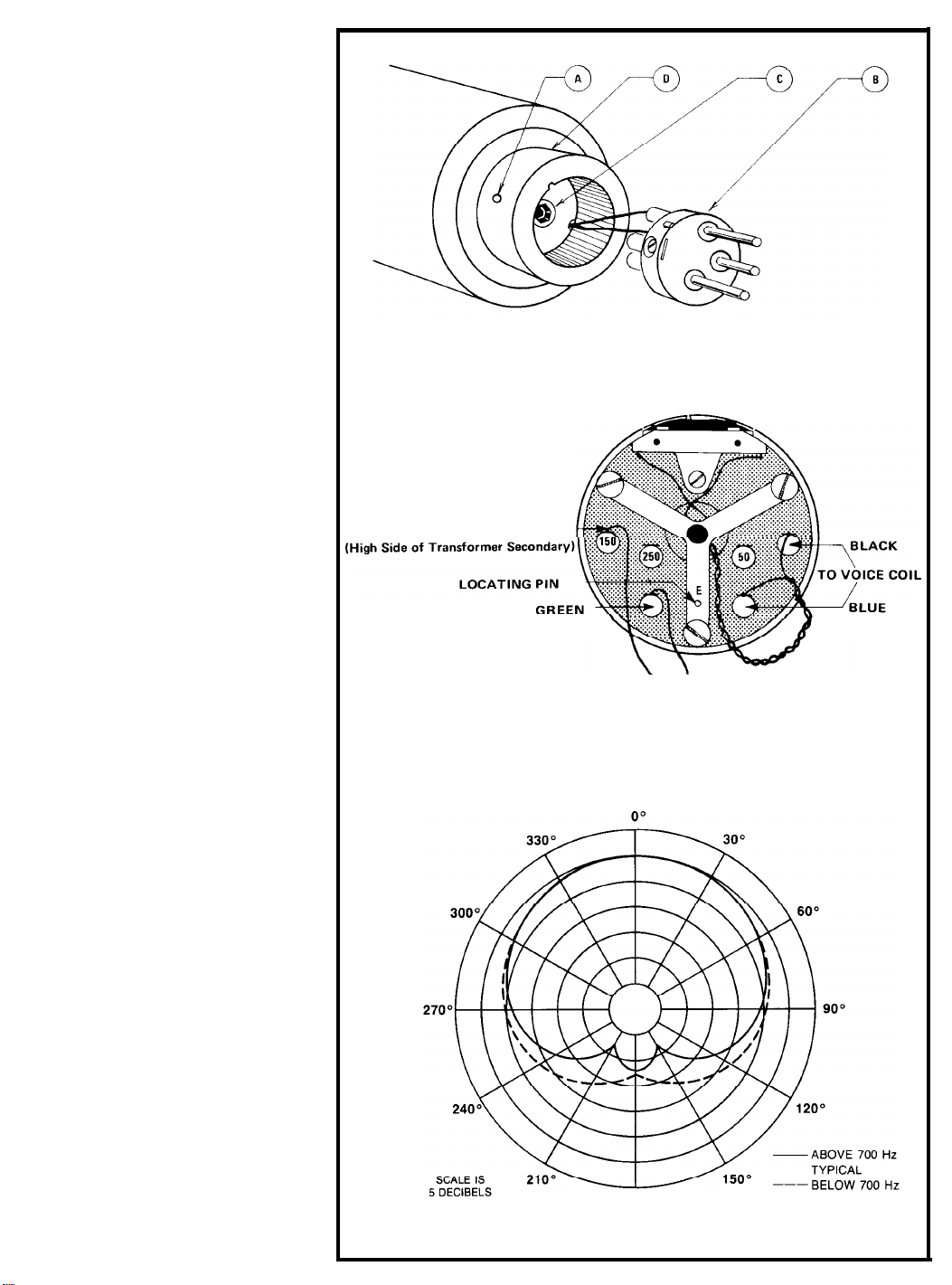
CHANGING IMPEDANCE CONNECTIONS
The RE20 is shippedwired for 150 ohms.
Fifty or 250 ohms may be obtained,
however, through the following procedure:
1.
2.
3.
4.
5.
6.
Refer to Figure 4. Insert a screwdriver in
small hole “A” at the rear of the
microphone. Turn counterclockwlseuntil
the captive screw “bottoms”.
Gently remove insert
“B”
exposing rear
cover
holddown
screw
“C”
(Allen head).
Disengage screw
“C”
from
main
microphone body with an Allen wrench.
Carefully remove rear cover
“D”
to
expose several solder terminals as
shown in Figure 5.
Impedance may now be changed by
moving the red wire to one of the open
solder terminals (marked 250 and 50).
Replace the rear cover by reversing
Steps 1 through 4.
Be
sure that locating

20
30 50
100 200 500 1000
2000 5000 10000 20000
FREQUENCY IN HERTZ
FIGURE
1
-
Frequency
Response
_ YELLOW
FIGURE 2 -Wiring Diagram
49mm
(1.
in.)
FIGURE 3 -Dimensions
pin
“E”
engages the rear cover
“D”
as
the cover is
re-installed.
Be sure that no
wires
are
pinched
in
the re-assembly
process.
The RE20
IS
now ready for operation at the
newly selected impedance.
ARCHITECTS’ AND ENGINEERS’
SPECIFICATIONS
The microphone shall be a cardioid type with
integral blast filter protecting all
acoustic
openings. The blast filter shall also serve as
a shock mount for the internal microphone
element. The microphone shall have a
wide-
range uniform frequency response from 45
to 18,000 Hz.
An integral
passive
network shall be
provid-
ed so that when the
filter
switch
is in the
“on” position, low frequency response shall
tilt down 4.5
dB
from 400 to 100 Hz.
With
switch in “off”
position,
microphone
shall be
essentially “flat” from
80
to 6,000 Hz, with a
broad 2.5
dB
rise
in
response from 6,000 to
14,000 Hz, and
nominally
down 3
dB
at
18,000 Hz. Response below 80 Hz shall be
nominally down 3
dB
at 45 Hz. Output level
shall be
-
57
dB
(0
dB
=
1
mW/Pascal).
Nominal
impedances of 50, 150, and 250
ohms shall be selectable by changing an
internal solder connection
Response at any angular position away from
the major axis shall be essentially similar to
the response on the major axis, but
attenuated uniformly at all frequencies by an
amount appropriate to that angular position.
Attenuation at frequencies from 45 to 10,000
Hz (refer to major axis signal value) shall
exceed 15
dB
at
180°
from major axis in
any plane. Attenuation above 10,000 Hz
shall exceed 13
dB.
Polar characteristics
shall be sufficiently uniform in all planes so
that it is, effectively, a cardioid of revolution.
There shall be a shield to prevent dust and
iron particles from
reaching
the diaphragm.
The case shall be made of steel. The
microphone
shall have a maximum diameter
of 54.4 mm (2.14 in.), a body diameter of
49.2 mm (1.94 in.), and a length of 216.7
mm (8.53
in.).
Finish shall be
non-reflecting
fawn beige
micomatte.
A 15 ft.,
two-
conductor shielded, broadcast-type, synthetic
rubber-jacketed cable
with
Switchcraft
A3F
connector installed, shall be provided. The

microphone shall have a
bult-in
connector
similar or equivalent to the
Switchcraft
A3M.
A No. 81715 stand adapter shall be
supplied. The
Electro-Voice
Model RE20 is
specified.
WARRANTY (Limited)
Electro-Voice Professional, PL
&
BK Series
Microphones are guaranteed against
malfunction
from any cause for a period of
two years from date of original purchase.
Also, these microphones are guaranteed
without
time
limit against malfunction in the
acoustic system due to defects in workman-
ship and material. Any active electronics
Incorporated in the microphone are
guaranteed for three years from date of
original purchase for parts and labor against
such malfunction. If such malfunction occurs,
microphone will be repaired or replaced (at
our option) without charge for materials or
labor if delivered prepaid to the proper
Electro-Voice service facility. Unit will be
returned prepaid. Warranty does not extend
to finish, appearance items, cables, cable
connectors, switches, or malfunction due to
abuse or operation under other than
specified conditions, nor does it extend to
incidental or consequential damages. Some
states do not allow the
exclusion
or
Iimitation
of incidental or consequential damages, so
the above exclusion may not apply to you.
Repair by other than Electro-Voice or its
authorized warranty
service
agencies will
void this guarantee. A list of authorized
warranty service centers is available from
Electro-Voice,
Inc., 600 Cecil Street,
Buchanan, Ml 49107
(AC/616-695-6831);
or
Electro-Voice West, 8234 Doe Avenue,
Visalia, CA 93291
(AC/209-651-7777).
This
warranty gives you specific legal rights, and
you may also have other rights which vary
from state to state.
Service and repair address for this product:
Electro-Voice, Inc., 600 Cecil Street,
Buchanan, Michigan 49107.
Specifications subject to change
without notice.
FIGURE 4
-
Disassembly
(Low Side of Transformer Secondary)
\
RED
FIGURE 5
-
Changing Impedance Connections
PER DIVISION
180°
TYPICAL
FIGURE 6
-
Polar Response
Other Mark IV Microphone manuals