JULY 19, 2017 8 STM-E, STM-EL, STM-EX & STM-ELX STERILIZERS
MISCELLANEOUS COMPONENTS
CAST-IN HEATING ELEMENTS
Located under the sterilizing cylinder is a bank of (3) U-
shaped heating elements. These elements are welded in
place in a protective aluminum shield. The elements can-
not be removed, and in the unlikely event that one or all
fail, the complete cylinder must be replaced.
THE LOW WATER CUT-OFF (MANUAL RESET)
Fastened to a special mounting brace behind the front
panel, the Low Water Cut-Off acts to shut off the complete
unit, should the water run dry. The Low Water Cut Off is
factory set, to shut the unit off when the cylinder tempera-
ture rises between 380oand 440° Fahrenheit.
When the Sterilmatic is turned on without water or the
water has been evaporated away, the temperature of
the aluminum sterilizing cylinder will rise and by heat in-
duction effect the Low Water Cut-Off. Its inner electrical
contacts will be forced open from heat expansion, thus
cutting off the ow of electric current to the heating ele-
ments. With the replacement of water into the cylinder
the cylinder temperature will drop and the contacts of the
Low Water Cut-Off can be again closed. The unit will only
restart after the manual button has been re-set.
THE ELECTRIC CONTACTORS
The Electric Contactors are located on the top of the unit,
underneath the top ue cover. These important compo-
nents receive an electrical impulse when the Timer is
turned on. When the unit reaches a pre-set pressure of
13-13.5 PSI the #1 switch will cut out causing the front
contactor to become de-energized. This, in turn, will dis-
connect the left and right bank of heaters and the timer
motor will start.
THE TIMER
The Sterilmatic is put into operation with the manual set-
ting of the timer. With the setting of the timer, an electrical
current is directed to the pressure control. The current en-
ergizes the pressure control, which activates the contac-
tor coils to cause a current ow to the heating elements.
When the cylinder pressure reaches 13 to 13.5 PSI, the
timer motor and pilot light are energized. At the end of
the cycle the timer will cut off the ow of electricity to all
the components except the exhaust, the exhaust solenoid
and the timer motor. They will revert back to their original
deactivated state. The timer motor and pilot light will con-
tinue to be energized after the timed sterilizer cycle has
been completed and for two additional minutes. Only after
this will the timer and white pilot light be de-energized. If
the timer fails to operate the Sterilmatic, replace it. The
timer is replaceable only as a complete unit as factory
repairs to it would not be practical in the economical inter-
ests of the customer.
THE STEAM PRESSURE GAUGE
The Steam Pressure Gauge registers the pressure of
steam, which is within the sterilmatic sterilizing chamber.
To replace this unit, it is necessary to disconnect the cop-
per tubing and to remove the two nuts holding the gauge
framework in place.
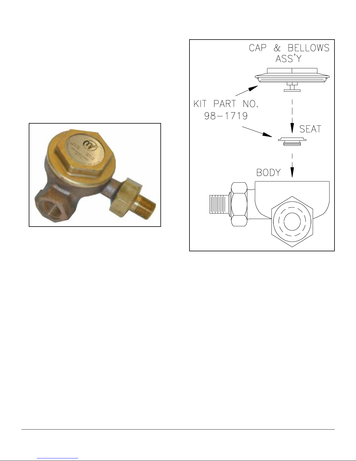
THE SAFETY VALVE
The Safety Valve is factory set to automatically open and
exhaust excess steam from within the sterilizing cylinder,
thereby assuring that operating pressures remain within
safe limits. The lever action of the safety valve must be
free to operate unrestricted at all times. If the Safety Valve
should leak continually with a pressure build-up or should
it cause an interruption on a sterilizing cycle premature-
ly (below 124° Centigrade on the temperature gauge),
it must be replaced. However, the temperature gauge
should rst be checked for accuracy.
THE FLUE
The Flue serves as a protective shield for the steam trap
safety valve, exhaust valve, and electrical components as
well as a mounting base for the control panel. The pres-
sure gauge, dial thermometer, exhaust valve switch and
timer, protrude through the control panel. The Flue cover
may be removed to allow more room for servicing the
control components. The control panel face may then be
removed by unscrewing the sheet metal screws, which
mount it to the Flue.
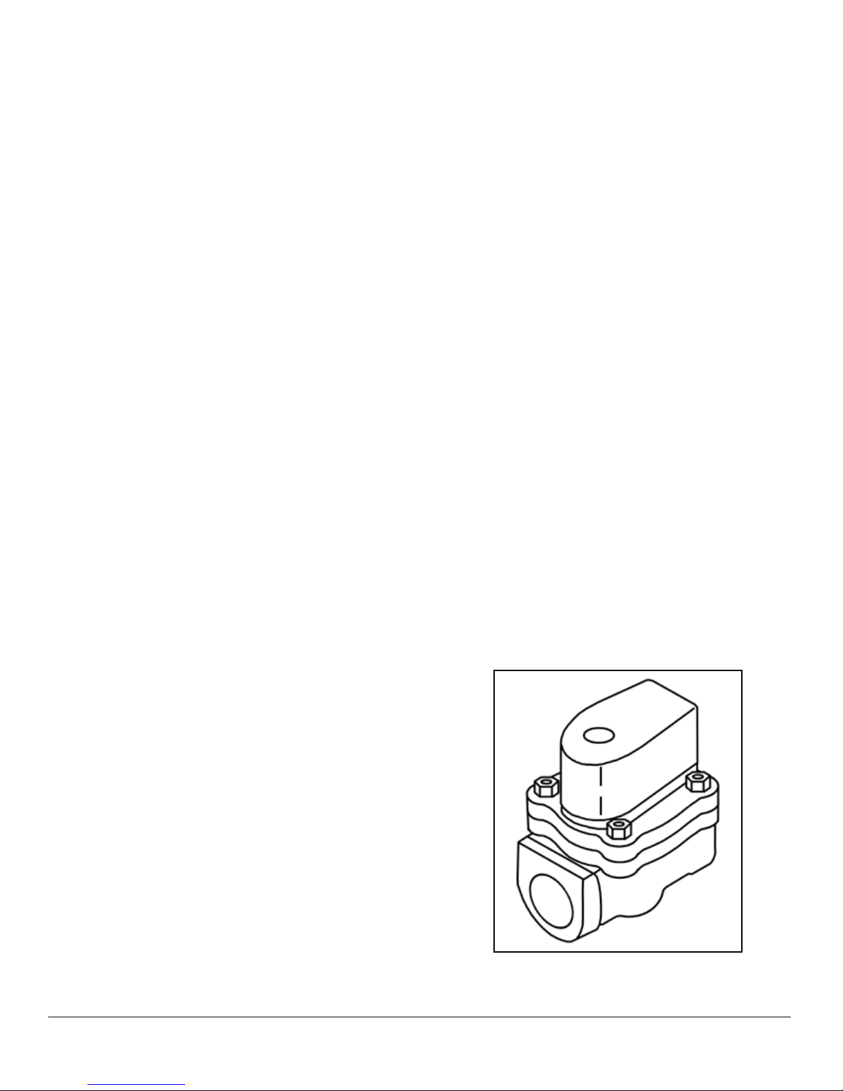
THE EXHAUST SOLENOID VALVE
The exhaust solenoid is normally closed and only opens
at the end of the cycle when it is energized.
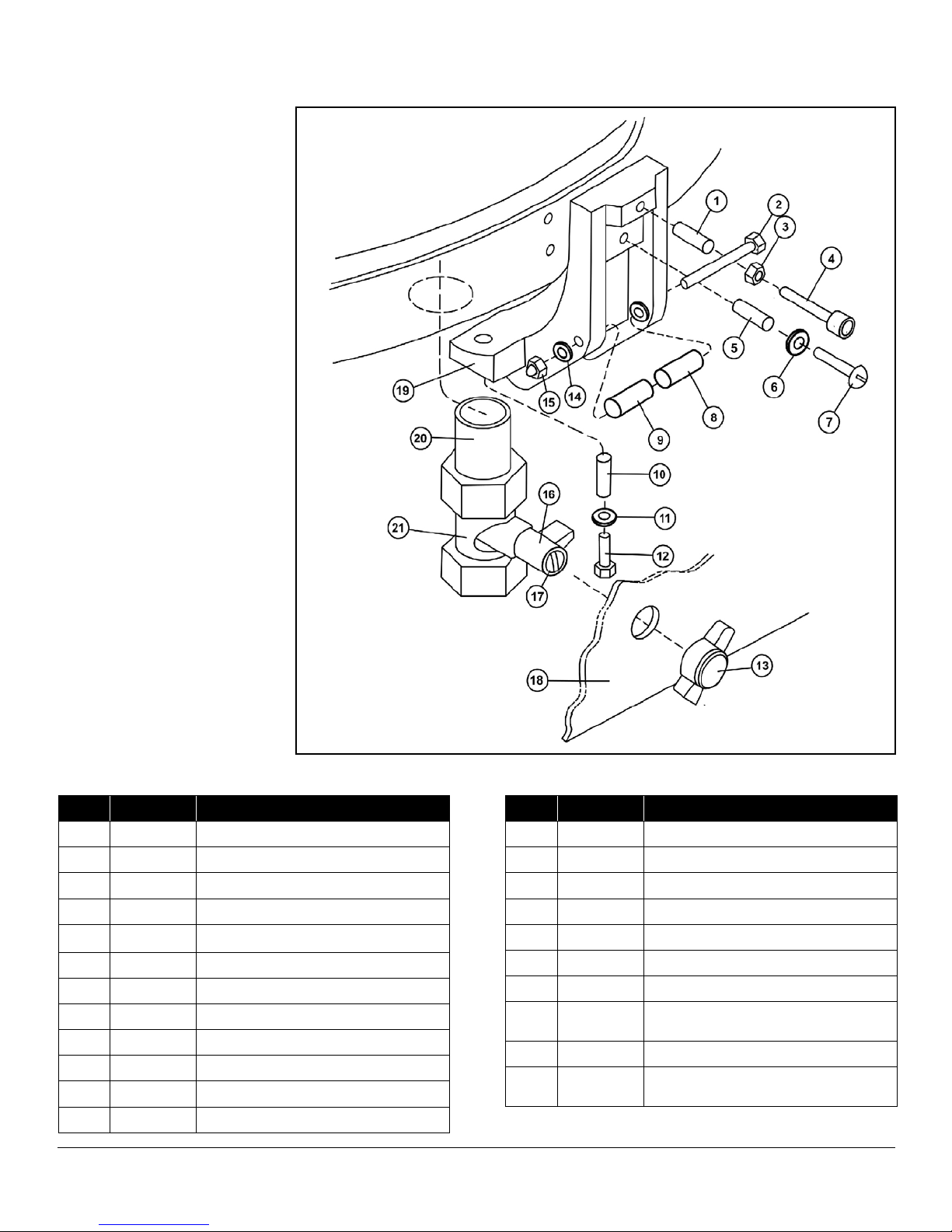
Figure 7