Market Forge Industries 2600PHE User manual

PURR-FECT HEIGHT SERIES ELECTRIC
CONVECTION OVEN
OWNER’S MANUAL
MODELS:
2600PHE
2692PHE
Printed in U.S.A. 35 Garvey Street lEverett lMA l02149
Tel: (617) 387-4100 lFax: (617) 387-4456 lOutside MA Fax: (800) 227-2659
E-Mail: CUSTSERV@mi.com lWebsite: www.mi.com
Form Number: S-6032 01/06 An Employee Owned Company
COVERING:
INSTALLATION
OPERATION
SERVICE & PARTS

i
TABLE OF CONTENTS
Your Energy Efficient Convection Oven ...........................................................................................
How the Oven Operates ....................................................................................................................
Operating Controls and Indicators ....................................................................................................
Operating Instructions .......................................................................................................................
Cleaning/Preventive Maintenance .....................................................................................................
Trouble-Shooting Guide ....................................................................................................................
Illustrated Parts List ...........................................................................................................................
Appendix ..........................................................................................................................................
i
i
i
1
2
2-3
4-8
9-11
YOUR ENERGY EFFICIENT CONVECTION OVEN
HOW THE OVEN OPERATES
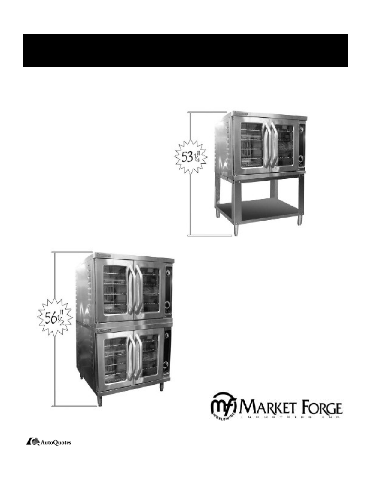
The Purr-fect Height Convection Oven is electrically
powered, high capacity ovens featuring high energy
efficiency. These ovens are designed to radically cut
power consumption, delivering the cooking power
of a 16 KW oven from only 11 KW’s of energy in-
put. Improvement of energy use is made possible by
a carefully designed insulating system which keeps
heat inside the oven longer.
A convector fan distributes heat uniformly through-
out the oven interior, for fast even roasting and
baking.
Like all Market Forge products, our ovens are built
to the highest standards of workmanship, employ-
ing only the finest materials and components Of
course, Power Saver II ovens are fully approved by
UL, UL Sanitation, and other official testing au-
thorities.
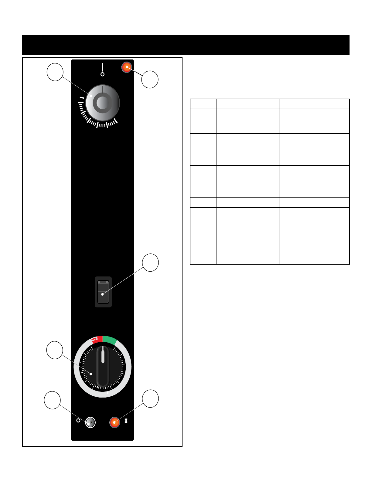
The Purr-fect Height Convection Oven operates by
use of two simple controls-a power switch for turn-
ing on the fan motor and control circuit, and a ther-
mostat for setting the oven temperature. The oven
is otherwise automatic. A thermostat maintains oven
temperature by cycling heating elements on and
off, with temperature fluctuating no more than 20°F
from the setting. Uniform distribution of heat within
the oven is assured by continuous operation of a con-
vector fan.
A 60-minute and Constant Heat timer serves as an
aid in using the oven, when the timer expires the
heating elements shut off. To prevent unnecessary
loss of heat when the doors are opened, a interlock
switch stops fan operation whenever the right-
side door is opened. Should the operator wish to
cool the oven, opening just the left- side door will
quickly ventilate the oven interior.

1
OPERATING CONTROLS & INDICATORS
The controls required to operate the oven are listed in the
following table. together with a short functional description
of each. The physical location of each control is shown in
FIG.1.
Check that power is available to the oven
Arrange shelf positions according to the item to be
cooked.
Close doors. Move fan switch to HIGH or LOW. Fan
should come on.
Set thermostat dial to desired cooking temperature. Ele-
ment indicator light should come on
Allow oven to preheat for about 5-10 minutes. Preheat-
ing is complete when indicator light goes out and the
buzzer sounds. Do not waste energy by turning the oven
on too early.
Load oven. The load should be adjacent to the oven, so
the doors will be open as short a time as possible.
Close doors. Set timer for desired cooking time.
Buzzer will sound at end of preset interval. Oven is
ready to unload.
If oven temperature is to be lowered, set the thermostat
to the desired temperature to cool interior. Fan will con-
tinue to run with left door open and right door closed.
Where indicator light comes on, oven is at lower tem-
perature. Close left door. When light goes off, oven is
ready for use.
For daily shutdown, place oven thermostat and power
switch in OFF position. For extended shut- down, leave
doors ajar as well.
1.
2.
3.
4.
5.
6.
7.
8.
9.
10.
FIG. 1 Operating Controls & Indicators
ITEM DESCRIPTION FUCTION
1 Thermostat Control Regulates oven temper-
ature. controls heating
element operation.
2 Thermostat Light Indicates when the
thermostat is calling for
heat and the elements
are ON.
3 Timer/Constant Heat Electrical timer to aid
in time ccoking cycles.
Controls oven and con-
stant heat mode.
4 Power Light Indicates power is ON.
5 Fan Switch Three position fan
switch. Controls fan
speed either HIGH/
LOW or in the middle
position the oven is
OFF.
6 Light Momentary Switch
0
C
O
O
K
5
10
15
20
25
30
35
40
45
50
55
60
C
O
N
S
T
A
N
T
O
F
F
246˚C
475˚F
246
450
204
400
177
350
149
300
121
250
93˚C
200˚F
OFF
OFF
HIGH FAN
LOW FAN POWER
ON
ON
LIGHT
6
4
5
3
1
2

2
CLEANING/PREVENTIVE MAINTENANCE
TROUBLE-SHOOTING GUIDE
A good preventive maintenance program in the form of
daily cleaning procedures is outlined in the following
steps:
Remove oven shelves and wash in mild detergent
and water. Rinse and dry.
Remove left and right hand shelf supports by lift-
ing up and out toward center of oven. Wash, rinse
and dry.
Remove fan baffle by lifting up and out. Wash,
1.
2.
3.
rinse and dry.
Wash interior sides, bottom, and top with mild
detergent and water. A stainless steel cleaner (not
polish) should be used for the interior. Rinse and
dry.
Replace fan baffle, shelf supports and shelves.
Wash both sides of doors, top & bottom trim using
a stainless steel cleaner. Rinse and dry.
4.
5.
6.
PROBLEM Probable Cause REMEDY
CONVECTOR FAN FAILS TO OPERATE.
a. Power to oven is off. Locates external circuit breaker for power and place in
ON position.
b. Power switch off. Place in ON position.
c. Right oven door open. Close Door.
d. Control circuit breaker off. Place in ON position.
e. Faulty circuit breaker, door interlock switch, fan
motor, or wiring.
Refer to wiring diagram or obtain outside service.
INDICATOR LIGHT FAILS TO LIGHT WITH FAN OPERATING, THERMOSTAT SET.
a. Indicator light burned out. Replace light. See service and parts manual for proce-
dure.
b. Electrical failure. Refer to wiring diagram or obtain outside service.
FAN OPERATION - NO HEAT.
a. Thermostat not set. Set thermostat.
b. Faulty contactor, wiring, electrical failure. Refer to wiring diagram or obtain outside service.
LIGHT INSIDE COOKING COMPARTMENT
a. Light fails to turn on. Replace bulb.

3
FIG. 2 Wiring Diagram
TROUBLE-SHOOTING GUIDE

4
RECOMMENDED SPARE PARTS LIST (P/N 98-3623)
PART NO. DESCRIPTION QTY.
10-7371 Power Switch 1
10-5052 Light, Fan Power 1
10-5052 Light, Heating Element 1
08-6308 Reed Switch 1
08-6472 Relay, 120V 1
08-6475 Relay, Socket 1
10-4714 Thermostat, 475oF1
09-5259 Thermostat, Knob 1
08-6464 Timer 1
08-3826 Timer, Knob 1
10-5944 Contactor 1
09-7248 Motor, 2 Speed 1
08-6351 Hi-Limit, Thermostat 1
08-6468 Fuse, 5Amp 2
09-6475 Transformer, 500VA 1
10-7395 Buzzer, 120 Volt 1
08-7978 Fan, Cooling 1
98-1717 Element, Heating 1
08-6469 Fuse, Holder 1
ILLUSTRATED PARTS LIST

5
ILLUSTRATED PARTS LIST
ITEM NO. PART NO. DESCRIPTION
1 08-7978 Fan, Cooling
2 08-6472 Relay, 120 Volts
3 08-6469 Fuse, Holder
4 08-6552 Terminal Strip
5 09-6575 Plug, Hole
6 10-5944 Contactor
7 98-1720 Terminal Block
8 08-6475 Base, Relay
9 98-3562 Panel, Electric Controls
10 08-6468 Fuse, 5 Amps
11 10-1720 Screw, #6-32 Thread x 1/2” Long, Stainless Steel
12 08-7993 Screw, #6-32 Thread x 1 1/2” Long, Stainless Steel
13 10-1761 Screw, #8-32 Thread x 3/8” Long, Stainless Steel
FIG. 3 Electric Control Panel with Probe Option

6
ILLUSTRATED PARTS LIST
FIG. 4 Glass Door Assembly
FIG. 5 Solid Door Assembly

7
ILLUSTRATED PARTS LIST
FIG. 6 Control Panel
ITEM
NO.
PART
NO. FIG. 5 DESCRIPTION
1 98-1717 Control Panel, Embossed
2 10-7395 Buzzer
3 10-5052 Light, Power & Fan
4 09-5259 Knob, Thermostat
5 10-4717 Thermostat
7 08-6597 Switch, Mode
8 08-3826 Knob, Timer
9 08-6464 Timer
10 10-7371 Switch, Power

8
ILLUSTRATED PARTS LIST
ITEM PART NO. DESCRIPTION QTY.
1 10-0631 6” Adjustable Leg 4
2 10-2564 Hex Hd. Cap Screw 3/4-10 x 1-1/2 Lg. 4
FIG. 8 2692PHE Mounting Assembly
NOTE:
Oven is shown with
side panel removed.
NOTE: Bottom oven
is shown with side panel
removed.
FIG. 7 2600PHE Mounting Assembly
ITEM PART NO. DESCRIPTION QTY.
1 99-4480 Open Stand with Shelf REF.
2 10-2002 Hex Hd. Cap Screw 3/8-16 x 1-1/4 Lg. 4
3 10-2401 Plain Washer 3/8” 8
4 10-2503 Lock Washer 3/8” 4
5 10-2302 Hex Nut 3/8-16 4
2600PHE Mounting Instructions:
1. Assemble stand (#1) per instructions
provided with stand.
2. Remove the side panels from oven.
3. Set the oven in place on top of the stand.
Align the holes in the bottom of the oven
with the sloted holes in the stand.
4. Fasten the oven to the stand with four
(#2) screws, eight (#3) washers, four
(#4) lock washers and four (#5) nuts, as
shown in figure 7.
5. Replace the side panels to the oven.
2692PHE Mounting Instructions:
1. Attach four (#1) feet to bottom of the
oven. Remove both side panels and
remove knock-outs in the top panels from
the bottom oven.
2. Set top oven in place on the bottom oven.
Align the holes in the top of the bottom
oven with the weld nhuts in the bottom of
the top oven.
3. Fasten the two ovens together with the
four (#2) screwa as shown.
4. Replace the side panels to bottom oven.

9
APPENDIX
SERVICE CONNECTIONS - Electrically Operated
EC Electrical Connection - Connection for incoming
power supply wire on terminal block.
EP Power supply - 1 3/8 (44mm) E access holes for
power supply wires. Use wire suitable for at least
90°C. Nominal amp per line wire per oven: 11 kW
VOLTS 1pH 3pH
208V 53 31
240V 46 27
480V --- 15
D Interior Drain Connection - 3/4” E (19mm) NPT to
open floor drain.
CW Cold Water Connection for optional spray hose 1/2”
NPT.
NOTE: Details of other electrical systems available upon request.
MODEL 2600PHE MODEL 2692PHE

10
A. OVEN PERFORMANCE
A.1 Verification Check List
1. Verify that the doors are properly aligned and that there is no interference occuring at room temperature and 400oF.
2. Verify that all screws and bolts are tight.
3. Verify that the blower fan can operate at high and low speeds.
4. Clean oven with a rag and run oven for 2 hours to burn off oil, clean interior prior to use.
5. Verify that the racks do not bind at 400oF.
Verify the accuracy of the oven’s thermostat at 350oF by comparing the temperature control setting to the temperature
at the center of the over (one thermocouple). The maximum difference is to be no more than +/- 5oF.
APPENDIX
PART
NO.
SPARE PARTS LIST
DESCRIPTION QTY.
10-7371 Power Switch 1
10-5052 Light, Fan Power 1
10-5052 Light Heating Element 1
08-6308 Reed, Switch 1
08-6472 Relay, 120 Volt 1
10-4714 Thermostat, 475oF 1
09-5259 Thermostat, Knob 1
08-6464 Timer 1
08-3826 Timer, knob 1
10-5944 Contactor 1
09-7248 Motor, 2 Speed 1
08-6351 Hi-Limit, Thermostat 1
08-6468 Fuse, 5 Amp 2
09-6475 Transformer, 500 VA 1
10-7395 Buzzer, 120 Volt 1
08-7978 Fan, Cooling 1
98-4066 Element, Heating, 208 Volt (Nest of three) 1
98-4067 Element, Heating, 240 Volt (Nest of three) 1
98-4065 Element, Heating, 480 Volt (Nest of three) 1
08-8004 Loctite 268 1
08-8003 RTV 106 Silicone Sealant 1
08-7999 * Hardware Kit (Fasteners) 1
98-3623 Complete Spare Parts Kit 1
08-8032 Replacement Bulb 1
08-8033 Replacement Lens 1
08-8034 Replacement Lens Gasket 1
* NOTE: For individual fasteners refer below for specific part numbers.

11
APPENDIX
PART
NO.
PARTS LIST OF FASTENERS
DESCRIPTION
LENGTH
(inches)
THREAD
SIZE QTY.
10-1864 SCREW CAP HEX HEAD 0.5 1/4”-20 77
10-1814 SCREW CAP HEX HEAD 0.75 1/4”-20 7
08-7840 NUT, SERRATED FLANGE 1/4”-20 73
08-7995 BOLT, HEX HEAD 3 5/16”-18 4
08-7956 NUT, SERRATED FLANGE 5/16”-18 8
10-2045 SCREW CAP HEX HEAD 0.5 #10-32 2
08-7996 TEK SCREW PHILLIPS PAN HEAD #2 0.5 #10-16 10
10-2146 SCREW, SLOTTED PAN HEAD 0.25 #6-32 26
10-1728 SCREW, PHILLIPS FLAT HEAD C-SUNK #8-32 8
08-7994 SCREW, PHILLIPS FLAT HEAD C-SUNK 1 #10-32 8
10-1749 SCREW, MACHINE ROUND HEAD 0.25 #8-32 6
10-1761 SCREW, MACHINE TRUSS HEAD #8-32 41
10-2571 NUT, KEPS #8-32 20
08-8005 NUT, SERRATED FLANGE #10-32 8
08-7992 SOCKET SET SCREW 1 #8-32 4
10-1790 SCREW, CAP HEX HEAD 1/4”-20 8
10-1939 BOLT, SHOULDER 0.5 1/4”-20 4
08-7991 SCREW, SLOTTED FLAT HEAD C-SUNK 0.5 #8-32 2
08-7990 SCRW, SLOTTED TRUSS HEAD 0.5 1/4”-20 3
08-3822 WASHER, STAINLESS STEEL TYPE B 1/4” 4
This manual suits for next models
1
Table of contents
Other Market Forge Industries Oven manuals

Market Forge Industries
Market Forge Industries 8000 Owner's manual

Market Forge Industries
Market Forge Industries 4200 User manual

Market Forge Industries
Market Forge Industries Premier PS-3E User manual

Market Forge Industries
Market Forge Industries Standard Depth 8000 User manual

Market Forge Industries
Market Forge Industries Standard Depth 8100 User manual

Market Forge Industries
Market Forge Industries 2500 HE Guide

Market Forge Industries
Market Forge Industries MSA-SB-2600 User manual

Market Forge Industries
Market Forge Industries 2624 User manual