manuals.online logo
Brands
  1. Home
  2. •
  3. Brands
  4. •
  5. marklin
  6. •
  7. Lighting Equipment
  8. •
  9. marklin H0 76371 User manual

marklin H0 76371 User manual

This manual suits for next models

1

Popular Lighting Equipment manuals by other brands

Life 39.9F70020C quick start guide

Life

Life 39.9F70020C quick start guide

EuroLite LED ML-20 user manual

EuroLite

EuroLite LED ML-20 user manual

LIGMAN OD-50141 installation manual

LIGMAN

LIGMAN OD-50141 installation manual

Home Accents Holiday 1002461144 instructions

Home Accents Holiday

Home Accents Holiday 1002461144 instructions

Experia IRiS Ripple Light instruction manual

Experia

Experia IRiS Ripple Light instruction manual

Erco Gecko Mounting instructions

Erco

Erco Gecko Mounting instructions

Inter-lux ZTA.100.Surface Installation and maintenance instructions

Inter-lux

Inter-lux ZTA.100.Surface Installation and maintenance instructions

Whelen Engineering Company TN Series installation guide

Whelen Engineering Company

Whelen Engineering Company TN Series installation guide

IKEA BJÖRKSPIREA manual

IKEA

IKEA BJÖRKSPIREA manual

Toolland PM 6640 instruction manual

Toolland

Toolland PM 6640 instruction manual

GTD GTD-LP200 user manual

GTD

GTD GTD-LP200 user manual

LIVARNO home 1105-W-UK manual

LIVARNO home

LIVARNO home 1105-W-UK manual

ProLights EclPar IPMFC user manual

ProLights

ProLights EclPar IPMFC user manual

Velvet EVO Series user manual

Velvet

Velvet EVO Series user manual

IDTOLIGHT GENT installation instructions

IDTOLIGHT

IDTOLIGHT GENT installation instructions

MAYTONI S35 installation manual

MAYTONI

MAYTONI S35 installation manual

MaxLite MLFP14DP4535 user manual

MaxLite

MaxLite MLFP14DP4535 user manual

SLV Elektronik 550621 instruction manual

SLV Elektronik

SLV Elektronik 550621 instruction manual

manuals.online logo
manuals.online logoBrands
  • About & Mission
  • Contact us
  • Privacy Policy
  • Terms and Conditions

Copyright 2025 Manuals.Online. All Rights Reserved.

76371/76372
Gleissperrsignal nieder/hoch
2
Die H0-Lichtsignale aus dieser Elektronik-
Serie bieten folgende Eigenschaften:
• Alle Hauptsignale und Gleissperrsignale beste-
hen aus einem Signal-Steuermodul und dem
zugehörigen Signalmast
• Die Signale können konventionell (Trafo 6647,
Stellpult 72720) oder Digital (z. B. mit Key-
board 6040, Central Station 60212) geschaltet
werden. Beim Schalten über Digital ist kein
weiterer Decoder notwendig.
• Vorbildgerecht geschieht das Umstellen der
Signalbilder durch weiches Überblenden.
• Bei Stellung „Langsamfahrt“ ist der Bediener für
eine Anpassung der Geschwindigkeit zuständig.
• Das Signal-Steuermodul kann nur zum
Ansteuern der Signale aus der zugehörigen
Märklin-Serie verwendet werden.
The H0 color light signals from this electronic
series offer the following features:
• All main and platform blocking signals consist
of one control module and the associated
signal mast.
• These signals can be operated conventionally
(6646/6647 transformer, 72720 control box) or
digitally (example: with 6040 Keyboard, Cen-
tral Station 60212). No additional decoder is
required when operating the signals digitally.
• The change in the signal aspects happens
prototypically with a gentle changeover.
• When the signal is set at „slow“, the operator is
responsible for adjusting the speed of the train.
• The signal control module can only be used
to control signals from the Märklin series that
belong to it.
3
Les signaux lumineux principaux H0 de cette
série électronique ont les caractéristiques
suivantes :
• Tous les signaux principaux avec signaux de
manoeuvre et les signaux de barrage consis-
tent en un module de commande et un mât de
signal correspondant.
• Les signaux peuvent être commutés en mode
conventionnel (transfo 6647, pupitre de com-
mande 72720) ou en mode Digital (p. e. avec
Keyboard 6040, Central Station 60212). En
cas de commande digitale, aucun décodeur
complémentaire n‘est nécessaire.
• Le changement de position du signal se fait
en douceur de façon réaliste (fondu enchaîné).
• En cas de position „ralentissement“, l‘opéra-
teur est tenu d‘adapter la vitesse.
• Le module de commande ne peut être utilisé
que pour la commande des signaux de la
série Märklin correspondante.
De H0-lichtseinen uit deze elektronische
serie hebben de volgende eigenschappen:
• Alle hoofd- en sperseinen bestaan uit een stuur-
moduul met bijbehorende seinmast.
•
de seinen kunnen conventioneel (trafo 6647, scha-
kelkast 72720) of digitaal (bijv. met een keyboard
6040, Central Station 60212) geschakeld worden. Bij
het digitale schakelen is geen extra decoder nodig.
• bij het omschakelen van het seinbeeld wordt,
overeenkomstig het voorbeeld, het vorige beeld
langzaam door het nieuwe beeld overstuurt.
• bij het seinbeeld „langzaam rijden“ moet de be-
dienaar zelf de snelheid van de trein aanpassen.
• de sein-besturingsmodule kan alleen gebruikt
worden voor het aansturen van de seinen uit
de bijbehorende Märklin-serie.
4
I segnali luminosi in H0 provenienti da questa serie
elettronica presentano le seguenti caratteristiche:
• Tutti i segnali principali e bassi di manovra
sono composti da un modulo di comando e
dal relativo palo portasegnali.
• Tali segnali possono venire commutati in modo
tradizionale (trasformatore 6647, quadro di co-
mando 72720) oppure in modo Digital (c). Nel
caso della commutazione tramite Digital non è
necessario alcun ulteriore Decoder.
• La modificazione degli aspetti di segnala-
mento avviene in modo fedele al prototipo
attraverso una leggera dissolvenza.
• In caso di disposizione su „marcia con rallen-
tamento“, è responsabile il manovratore per
un adeguamento della velocità.
• Il modulo di comando del segnale può venire
utilizzato soltanto per il controllo dei segnali
appartenenti alla corrispettiva serie Märklin.
La señales luminosas de la serie electrónica
tienen las siguientes características:
• Todas las señales principales y de bloqueo
de la vía están compuestas por un módulo de
control y su correspondiente poste.
• Las señales se pueden gobernar de forma
convencional (transformador 6647, pupitre
72720) o también Digital (p.e. con el Keyboard
6040, Central Station 60212). Para un gobier-
no Digital no hace falta ningún decoder.
• Transición suave del cambio de luces, al igual
que la realidad.
• El usuario debe adaptar la velocidad de su
locomotora si la señal marca „marcha lenta
prevista“.
• El módulo de gobierno de señales solamente
sirve para las señales de la serie de Märklin.
5
De nye H0-lyssignaler i denne elektronikserie
har følgende egenskaber:
• Alle hoved- og sporspærresignaler består af et
styremodul og den tilhørende signalmast.
• Signalerne kan tilsluttes konventionelt (Trafo
6647, Styrepult 72720) eller digitalt (f.eks. med
Keyboard 6040, Central Station 60212). Ved
digital tilslutning er der ikke brug for ydeligere
dekoder.
• Ligesom på forbilledet sker omstillingen af
signalbillederne ved hjælp af blød ind- og
udblænding.
• Ved stillingen „Langsom kørsel“ skal brugeren
sørge for tilpasning af hastigheden.
• Signal-styremodulet kan kun anvendes til sty-
ring af signaler i den tilhørende Märklinserie.
H0 ljussignaler från denna elektronikserie
erbjuder följande egenskaper:
• Alla huvud- och spårspärrsignaler består av
en styrmodul och tillhörande signalmast.
•
Signalerna kan ställas konventionellt (Trafo 6647,
Ställpult 72720) eller digitalt (t ex med Keyboard
6040, Central Station 60212). Vid koppling via
Digital behövs ingen ytterligare dekoder
.
• Omställning av signalbilderna sker före-
bildstroget genom mjuk övergång.
• Vid inställning „krypfart“ är användaren skyl-
dig att anpassa hastigheten själv.
• Signalstyrmodulen kan endast användas för att
styra signalerna från tillhörande Märklinserie.
6
Signalbilder beim Vorbild
Signal Aspects in the Prototyp
Positions signalétiques réelles
Seinbeelden bij het voorbeeld
Signalbild Gleissperrsignal:
Signal indication of the platform blocking signal:
Aspect du signal de barrage:
Seinbeeld hoofdsein:
Imagen de la señal de bloqueo de la vía:
Aspetto del segnale basso di manovra:
Signalschema spårspärrsignal:
Signalbillede sporspærresignal:
Bedeutung:
Meaning:
Signification:
Betekend:
Significado:
Significato:
Innebörd:
Betydning:
Rangierfahrt erlaubt
Switching Maneuver Allowed
Circulation autorisée
rangeren toegestaan
Aniobras permitidas
Manovra consentita
rangerfart tillåtet
Rangering tilladt
Halt
Stop
Arrêt
Stop
Paro
Arresto
Stopp
Stop
Posiciones de las señales en la realidad
Aspetti del segnalamento nel caso del prototipo
Signalbilder hos förebilden
Signalbilleder på forbilledet
7
Fahrstrom:
Track Current:
Courant traction :
Rijstroom:
Corriente de tracción:
Corrente di trazione:
Körström:
Kørestrøm:
ein
on
branché
aan
encendida
inserita
till
til
aus
off
débranché
uit
apagada
esclusa
från
fra
8
Einstellen der Digital-Adresse
Hinweis: Bei konventionellem Anschluss ist
keine Adresseinstellung notwendig.
Allgemeine Hinweise:
• Einstellen der Adresse ist nur möglich, wenn
sich das Signal-Steuermodul mit angeschlos-
senem Signalmast in der Verpackung befindet
(mit eingerasteten Adressierstifte in der Verpa-
ckung am Signal-Steuermodul).
• Benötigte Digitalkomponenten zum Einstellen
der Adresse: 1x Control Unit, 1x Transformer,
1 - 2 Keyboard(s) oder 1x Central Station
•
Die Adresse wird nur im Gleisperrsignal gespei-
chert
.
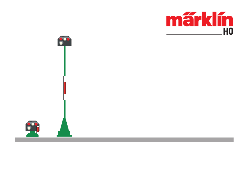
Tastaturbelegung am Keyboard:
Gleissperrsignal: 1 Tastenpaar am Keyboard
Tastaturbelegung an der Central Station:
Diese entnehmen Sie bitte der Anleitung zur
Central Station
Beispiel:
Signaltyp: Niedriges oder hohes Gleissperrsignal
Schalter: Tastenpaar 3 am Keyboard Nr. 1
Vorgehensweise zur Adresseingabe
1. Control Unit, Keyboard und Transformer an-
schließen. Control Unit noch nicht einschalten.
2. Signal-Steuermodul mit angeschlossenem
Hauptsignalmast in der Blister-Verpackung
mit der integrierten Kontaktfeder belassen (!)
Nur das braune und gelbe Anschlusskabel
vom Signal-Steuermodul an die braune und
rote (!) Ausgangsklemme an der Control Unit
anschließen.
3. Keyboard- Adresse auf die gewünschte Adres-
se stellen. In unserem Beispiel (Keyboard Nr. 1)
alle 4 Codierschalter in Stellung „off“.
4. Control Unit 6021 einschalten. Taste „stop“
drücken.
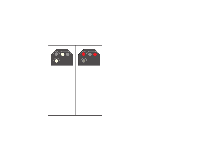
5. Taste „go“ drücken. Das Hauptsignal beginnt
abwechselnd zwischen 2 Signalbildern umzu-
schalten. Sollten die nachfolgenden Schritte
nicht innerhalb einiger Sekunden begonnen
werden, so beendet die Elektronik automa-
tisch den Adressiervorgang.
6. Grüne Taste am 3. Tastenpaar des Keyboards
solange drücken, bis alle LED am Signal
leuchten. Erst jetzt die Taste loslassen.
7. Control Unit ausschalten, Signal und Sig-
nal- Steuermodul können jetzt in die Anlage
eingebaut werden.
9
Hinweis:
• Bei langen Pausen während der Programmie-
rung beendet das Signal den Programmiermo-
dus ohne Änderung. In diesem Fall mit dem
kompletten Adressiervorgang wieder vorne
beginnen. Während der Adressierung darauf
achten, dass die Pausen zwischen den einzel-
nen Tastaturbefehlen nicht zu lange sind.
• Nach Beendigung oder Abbruch der Pro-
grammierung schaltet das Signal nach einigen
Sekunden in den Demonstrationsmodus. In
diesem Modus werden verschiedene Signal-
bilder des jeweiligen Signaltyps dargestellt.
• Vor dem Austesten des Signals muss die
Steuerelektronik aus der Verpackung entfernt
werden.
Setting the Digital Address
Important: No address needs to be set for con-
ventional wiring connections
General Information:
• The address can be set only when the signal
control module with the signal mast connect-
ed to it is in its packaging. (with the address
pin snapped into the packaging on the signal
control module).
• The necessary digital components for setting
the address: 1 each Control Unit, 1 each trans-
former, 1 - 2 Keyboard(s), or 1 x Central Station
• The address is only stored in the track block
signal.
Button Assignment on the Keyboard:
Track block signal: 1 key pair on keyboard
Control button assignment on the Central Station:
Please see the instructions for the Central Sta-
tion about this topic.
Example:
Signal type: low or high track block signal.
Switch: key pair 3 on keyboard no. 1
10
Procedure for Entering the Address
1. Connect the Control Unit, Keyboard, and
transformer. Do not turn the Control Unit on
yet.
2. Leave the signal control module with con-
nected main signal mast in the blister package
with the integrated contact spring. Connect
only the brown and the yellow wires from the
signal control module to the brown and red (!)
terminal clips on the Control Unit.
3. Set the Keyboard address to the desired
address. In our example (Keyboard No. 1) all
four coding switches at the „off“ position.
4. Turn on the 6021 Control Unit. Press the
„stop“ button.
5. Press the „go“ button. The home signal will
begin to switch between 2 signal aspects.
If the following step does not begin within
several seconds, the electronic circuit will end
the address setting process automatically.
6. Press the green button on button pair 3 of the
Keyboard until all of the LED‘s on the signal
light up. Only release the button at this point.
7. Turn the Control Unit off. The signal and the
signal control module can now be installed on
the layout.
Note:
• For long breaks during programming, the
signal terminates the programming mode
without a change. In this case, start from the
beginning again with the complete addressing
procedure. While addressing is taking place,
ensure that the breaks between the individual
keyboard commands are not too long.
• Once the programming has ended or has
been cancelled, the signal switches to dem-
onstration mode after a few seconds. In this
mode, various signal aspects of the respective
signal type are displayed.
• The control electronic circuit must be removed
from the packaging before testing the signal.