MARLO NXT2 Series User manual

MGT 240M–1200M
SYSTEM 7 – TWIN ALTERNATING
3” NXT2 SERIES
MODEL NO:
SERIAL NO:
DATE INSTALLED:
DEALER:
COMPLETE FOR FUTURE REFERENCE:
COMMERCIAL WATER CONDITIONER
INSTALLATION, OPERATION, AND MAINTENANCE MANUAL
Standard Image
Equipment appearance may differ.
Twin system shown with skid mount option.
8-634

MGT 240M–1200M NXT2 3” TWIN ALTERNATING
Inspection Requirement
Prior to Loading Media
1. Inspect condition of upper distributor piping. Verify
fittings are tight and positioned as shown.
2. Inspect condition of strainers, laterals and hub through
top or side access ports. Verify fittings are secured
to hub.
3. DO NOT load media if damaged components are
observed. Contact factory.
4. Installer is responsible for media loss into treated water
resulting from failure to report and repair damaged
components inside media tank prior to media loading.
5. INSTALLER WARNING:
Refer to installation instructions for media loading
procedure. Improper loading of media will damage
components inside media tank.
PRIOR TO
Media Loading
AFTER
Media Loading
SIDE
VIEW
Lateral
Hub
Distributor Tube
Media Tank
Softener/
Filter Media
Gravel
Media
TOP
VIEW
Media Tank
Lateral
Hub
5-272
IMPORTANT PLEASE READ:
• Warranty of this product extends to manufacturing defects.
• The information, specications and illustrations in this manual are based on the latest information
available at the time of printing. The manufacturer reserves the right to make changes at any time
without notice.
• This product should be installed by a plumbing professional on potable water systems only.
• This product must be installed in compliance with all local and state and municipal plumbing and
electrical codes. Permits may be required at the time of installation.

TABLE OF CONTENTS
SYSTEM INFORMATION
Product Warranty...........................................................................................................................................................1
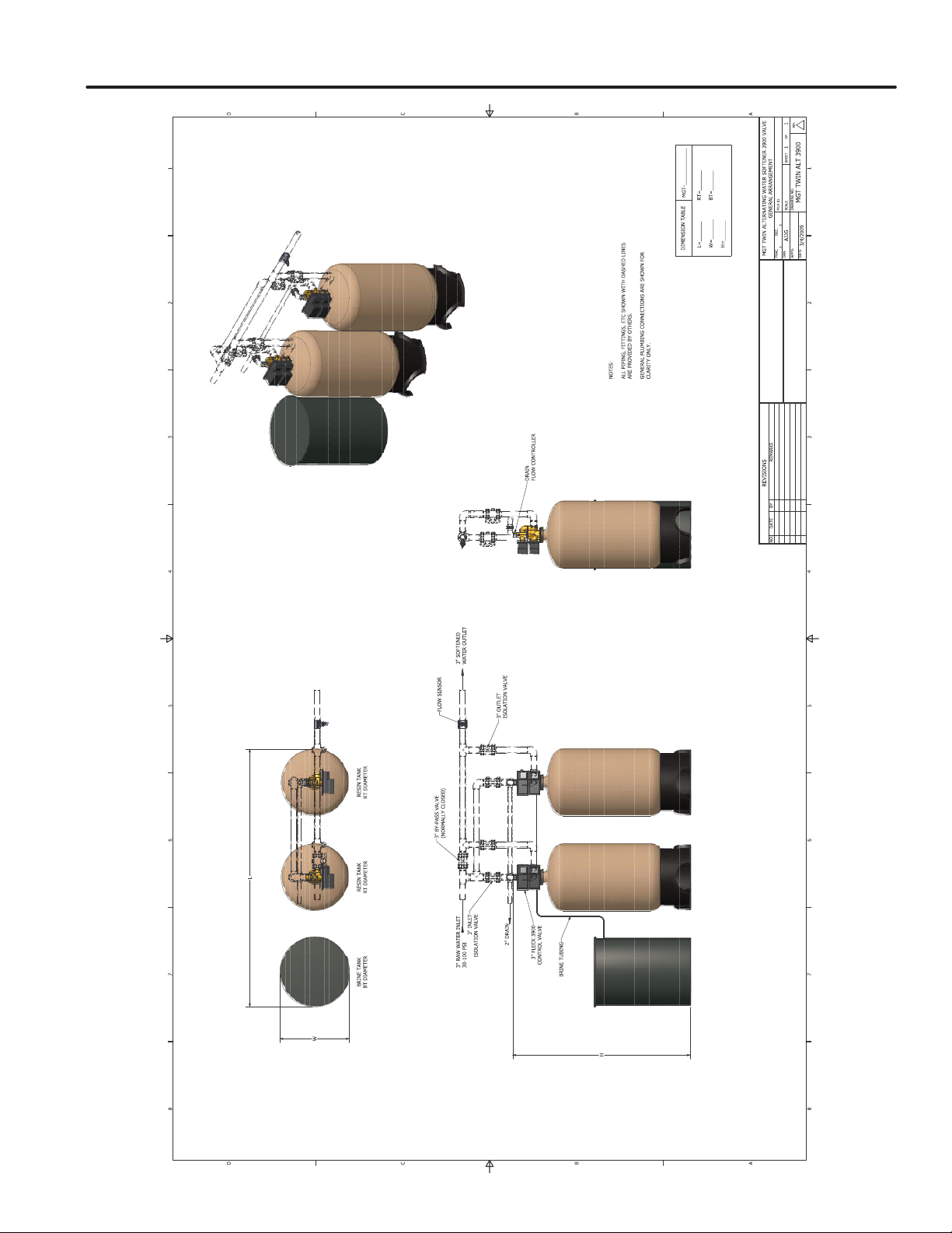
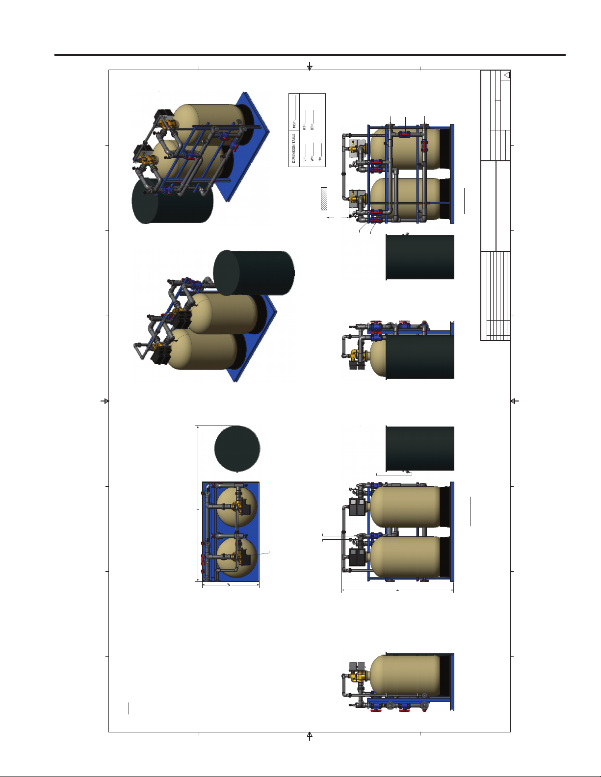
General Arrangement Drawings ....................................................................................................................................2
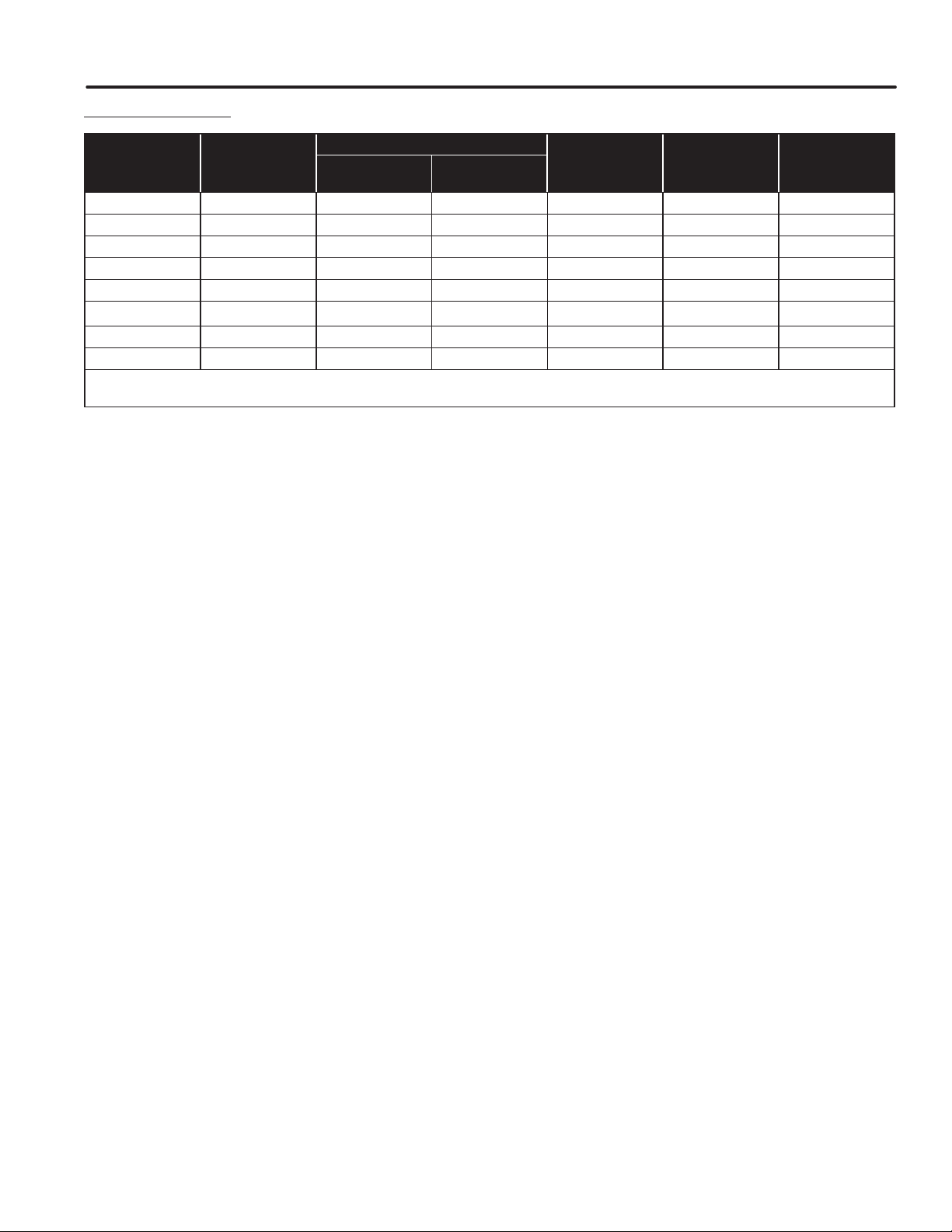
Dimension Chart ...........................................................................................................................................................4
Speci ication Chart .......................................................................................................................................................5
INSTALLATION
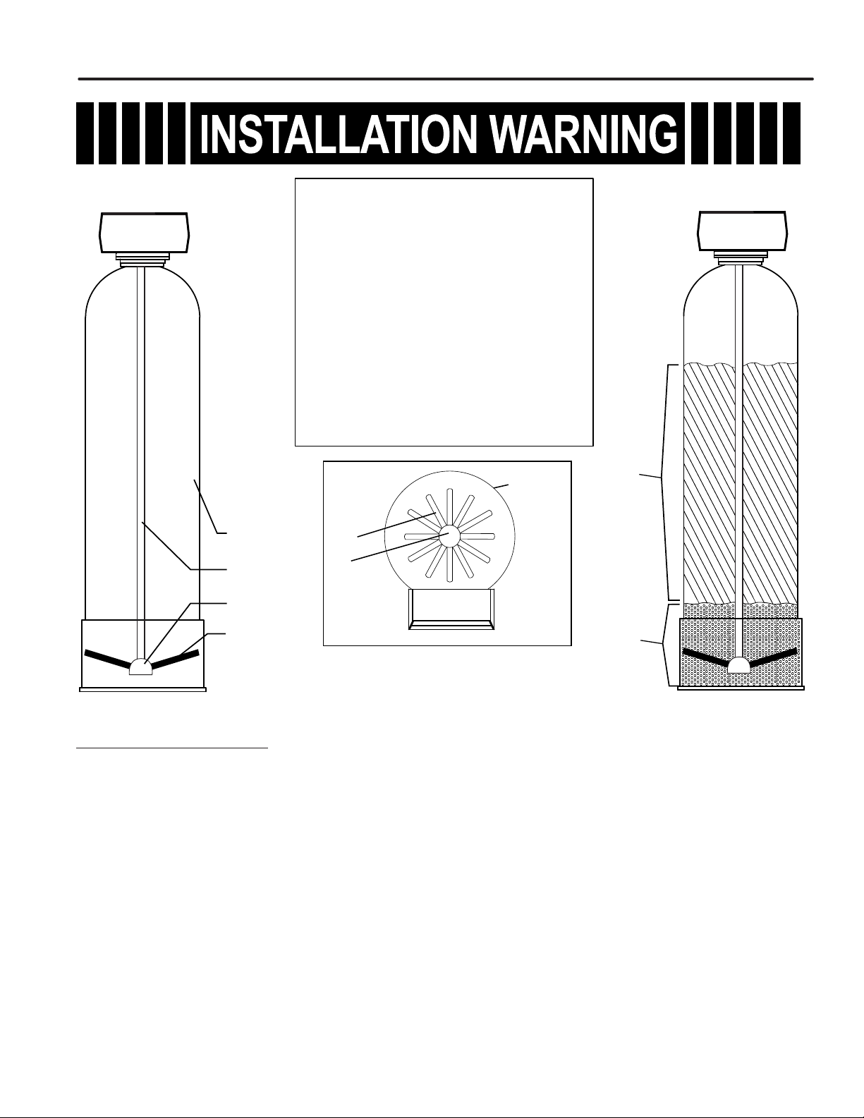
General Information.......................................................................................................................................................6
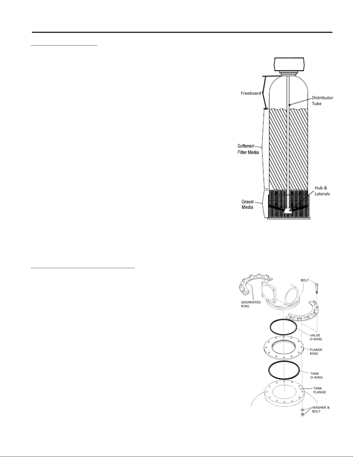
Loading Softener ..........................................................................................................................................................7
Mounting Control Valve ................................................................................................................................................7
Brine Tank Installation .................................................................................................................................................. 8
Mounting Water Meter ................................................................................................................................................. 10
Network Communication Cables/Connections ............................................................................................................ 10
Power Supply Wiring ...................................................................................................................................................11
Connection Piping Installation .....................................................................................................................................11
OPERATION
Timer Display Features ...............................................................................................................................................12
System Operation........................................................................................................................................................13
Timer Operation...........................................................................................................................................................13
Start-Up Procedures....................................................................................................................................................15
User Mode Programming Flow Chart..........................................................................................................................16
Batch Size Calculation.................................................................................................................................................17
Diagnostic Mode Flow Chart .......................................................................................................................................18
Master Programming Flow Chart.................................................................................................................................19
Master Programming Guide ........................................................................................................................................21
Flow Diagrams.............................................................................................................................................................22
Wiring Diagram............................................................................................................................................................24
MAINTENANCE
Powerhead Assembly .................................................................................................................................................25
NXT2 Timer Assembly.................................................................................................................................................27
Control Valve Assembly...............................................................................................................................................28
Brine Injector Assemblies ...........................................................................................................................................30
Meters and Flow Sensors ...........................................................................................................................................34
Brine Tank Assemblies ...............................................................................................................................................37
Service Assemblies ....................................................................................................................................................41
Troubleshooting...........................................................................................................................................................42
MGT 240M–1200M NXT2 3” TWIN ALTERNATING

MGT 240M–1200M NXT2 3” TWIN ALTERNATING
SYSTEM INFORMATION
1
COMMERCIAL AND INDUSTRIAL PRODUCT WARRANTY
Manufacturer warrants all commercial and industrial water treatment products manufactured and/or distributed by it to
be free from defects in materials and workmanship for a period of one (1) year after installation or eighteen (18)
months from the date of shipment, whichever comes rst. The berglass mineral tank(s) alone have a warranty for a
period of ve (5) years from the date of shipment. If within that period any products shall be proven to Manufacturer’s
satisfaction to be defective, those products will be replaced or the price refunded at Manufacturer’s option.
Manufacturer’s obligations or nonperformance, defective, or any damage caused by its products or their use, and
buyer’s exclusive remedy therefore, shall be limited to product replacement or refund and shall be conditioned upon
Manufacturer’s receiving written notice together with a demand for such replacement or refund:
The foregoing warranty is exclusive and in lieu of all other expressed implied warranty (except of title) including but
not limited to implied warranty of merchantability and tness for particular purpose.
Manufacturer will not be subject to and disclaims the following:
1. Any other obligations or liabilities arising out of breach of contract or out of warranty.
2. Any obligations whatsoever arising from tort claims (including negligence and strict liability or arising under other
theories of law with respect to products sold or services rendered by Manufacturer or any undertakings, acts, or
omissions relating thereto.
3. All consequential, incidental, and contingent damages.
Labor charges, charge backs or handling charges are excluded from Manufacturer’s warranty provisions.
COMMERCIAL AND INDUSTRIAL WATER SOFTENER GUARANTEE
Under normal operating conditions:
1. The softener efuent shall be zero soft as determined by a soap test.
2. The loss of softening resin through attrition during the rst three (3) years shall not exceed 3% per year.
3. The softening resin shall not be washed out of the system during backwash.
4. The color and turbidity of the softener efuent shall not be greater than the incoming water.

MGT 240M–1200M NXT2 3” TWIN ALTERNATING
SYSTEM INFORMATION
2
5-232

MGT 240M–1200M NXT2 3” TWIN ALTERNATING
SYSTEM INFORMATION
3
FRONT VIEW
BACK VIEW
1
1
2
2
3
3
4
4
5
5
6
6
7
7
8
8
A A
B B
C C
D D
DATE
FRAC.
DRN.
APP'D.
_
DEC.
_
DRAWING NO.
SCALE
FILE ID.
SHEET
REV.
OF
MGT-600-3 TW-ALT SKID - PVC
GENERAL ARRANGEMENT
11
Anthony
2/18/2010 1
REVISIONS
NO. BY REMARKS
112/13/13 AJJG ADDED VACUUM RELIEF VALVES
DATE
RESIN TANK BRINE TANKRESIN TANK
AUTOMATIC BACKWASH
FLOW CONTROLLER
BY-PASS
VALVE
(NORMALLY
CLOSED)
3" RAW WATER
INLET 30-100 PSIG
3" SOFT WATER
OUTLET
INLET ISOLATION
VALVE
OUTLET ISOLATION
VALVE
OVER FLOW
TO DRAIN
NOTES:
1. OVERALL HEIGHT IS FOR REFFERENCE ONLY. ACTUAL
HEIGHT MAY VARY BASED ON TANK PROVIDED.
ALLOW 36" FOR
RESIN LOADING
WATER INLET
PRESSURE GAUGE
AND SAMPLE COCK
(TYP.)
WATER OUTLET
PRESSURE GAUGE
AND SAMPLE COCK
(TYP.)

MGT 240M–1200M NXT2 3” TWIN ALTERNATING
SYSTEM INFORMATION
4
DIMENSION CHART
MODEL INLET SIZE
(Inches)
TANK SIZE LENGTH
(Inches)
WIDTH
(Inches)
HEIGHT*
(Inches)
SOFTENER
(Inches)
BRINE
(Inches)
240 3 24x72 24x50 89 24 95
300 3 24x72 24x50 89 24 95
450 3 30x72 30x50 115 30 93
600 3 36x72 39x60 129 39 94
750 3 42x72 39x60 140 42 113
900 3 42x72 42x60 143 42 113
1050 3 48x72 42x60 155 48 113
1200 3 48x72 42x60 155 48 113
*Leave a minimum 24 inch clearance to the height of the unit for loading media.
Dimensions are for general arrangement use only.

MGT 240M–1200M NXT2 3” TWIN ALTERNATING
SYSTEM INFORMATION
5
SPECIFICATION CHART
SYSTEM SIZE
MODEL 240 300 450 600 750 900 1200
VALVE SIZE (IN) 3333333
MAX CAPACITY (KILOGRAINS) 240 300 450 600 750 900 1,200
MIN CAPACITY (KILOGRAINS) 160 200 300 400 500 600 800
FLOWRATE (GPM)
CONTINUOUS FLOWRATE (GPM) 120 114 160 185 200 165 205
PEAK FLOWRATE (GPM) 170 150 213 250 268 225 275
BACKWASH & FAST FLUSH (GPM) 15 15 25 30 35 35 35
BRINE DRAW & RINSE (GPM) 3.2 3.2 3.5 4.5 6.5 6.5 10
BRINE TANK REFILL (GPM) 2 2 5 5 10 10 10
TIMER
SETTINGS
BACKWASH & FAST FLUSH (MIN) 10 10 10 10 10 10 10
BRINE DRAW & RINSE (MIN) 60 60 80 80 80 90 90
FAST FLUSH (MIN) 10 10 10 10 10 10 10
BRINE TANK REFILL (MIN) 20 25 15 20 13 15 20
SOFTENER
TANK
SIZE (IN) 24x72 24x72 30x72 36x72 42x72 42x72 48x72
GRAVEL (LBS) 120 120 225 400 400 650 1000
RESIN (FT3)8 10 15 20 25 30 40
FREEBOARD (IN) 30 21 22 23 23 15 15
BRINE SYSTEMS
EQUIPMENT
TANK SIZE 24x50 24x50 30x50 39x60 39x60 42x60 42x60
MAX SALT STORAGE (LBS) 550 450 640 1700 1700 2000 1700
INJECTOR CODE 4456778
INJECTOR COLOR GRN GRN RED WHT BLU BLU YEL
MAX
SALT DOSAGE- MAX (LBS) 120 150 225 300 375 450 600
REFILL TIME - MAX (MIN) 20 25 15 20 13 15 20
MIN
SALT DOSAGE- MIN (LBS) 48 60 90 120 150 180 240
REFILL TIME - MIN (MIN) 8 10 6 8 5 6 8
REGENERATION WASTE VOLUME (GAL) 520 544 860 1020 1210 1315 2100
NOTES:
1. FLOW RATES
Continuous: pressure loss does not exceed 15 psig.
Peak: pressure loss does not exceed 25 psig
Backwash & Flush: maximum flow to drain
Brine & Rinse: Injector flow to drain
Brine Tank Refill: flow to refill Brine Tank
2. SOFTENER TANK
Freeboard: distance in inches from surface of resin to top sealing flange of tank
3. SALT DOSAGE
Maximum 15 lbs./cu.ft. - regeneration efficiency: 2,000 grains/pound of salt
(factory setting)
Maximum 6 lbs./cu.ft. - regeneration efficiency: 3,000 grains/pound of salt
4. REGENERATION WASTE VOLUME - Total gallons water discharged per
regeneration
5. OPERATING LIMITS:
Minimum operating pressure is 30 psi.
Maximum operating pressure is 120 psi.
Standard units are designed to soften unheated water within the range of
35-100°F.
6. POWER
Power requirements are 120 Volt, 60 Hertz, Single Phase, 2 amps
noninterrupted.
7. SALT
Salt specifications are pelletized or solar salt, 99% pure, containing
less than 1% insolubles (see Brine Tank Installation on page 8)

MGT 240M–1200M NXT2 3” TWIN ALTERNATING
INSTALLATION
6
INSTALLATION INSTRUCTIONS WATER SOFTENERS
GENERAL INFORMATION
1. Operating pressure range is 30-100 psi. If pressures over 100 psi are encountered, a regulator must be installed.
NOTE: The control valve will not operate correctly if feeding into an atmospheric tank. A pressure control device
must be added to the outlet to maintain the minimum pressure.
2. Power requirements are shown on inside cover of the control valve. You can also tell by wire color on the motor.
Black wires are 115 volt. Yellow wires are 220 volt. Blue wires are 24 volt.
3. Standard units are designed to soften unheated water not to exceed 100F. Special valve assemblies are available
to handle heated water supplies exceeding 100 F. Consult factory if applicable.
4. Each softener tank is shipped with distributor manifold and control valve preassembled. Take care when uncrating
and erecting so that no items are damaged.
5. The distributor assembly has been shipped inside the berglass mineral tank. Check to make sure that there is no
damage to the riser pipe, baskets, laterals or hub (if applicable).
NOTE: A prelter should be used on installations in which free solids are present
LOCATE SOFTENER
1. Select a location that is accessible and near a oor drain that has adequate carrying capacity to handle the
softener backwash ow (see specication table for ow rate). Allow a minimum of 24” above the tank for
loading media.
2. Erect the softener tank(s) on a concrete or other rm foundation and level.
3. Position the brine tank according to the illustration and supplementary brine tank information. Keep the brine tank
as close as possible to the softener tank(s).
Note: The distance between the softener and brine tanks will affect the brine injector performance, as the distance
increases the injector performance decreases. This may cause an inadequate regeneration. Maximum
recommended distance is 5 ft.
4. A grounded electric receptacle is required for the control valves.

MGT 240M–1200M NXT2 3” TWIN ALTERNATING
INSTALLATION
7
LOAD SOFTENER TANK
IMPORTANT: Be sure to visually inspect the lower laterals prior to loading
the media. Check to make sure each lateral is rmly threaded into the hub
1. Fill tank(s) approximately 1/3 full of water using a hose, bucket, etc. Plug the
PVC distributor manifold pipe using a plastic cap, cork, rag, etc. NO gravel or
resin should go into this distributor manifold pipe.
2. Verify the distributor manifold is center in the tank with the distributor resting
on the bottom of the tank. Verify the riser pipe is still plugged.
NOTE: Reference the specication table in the front of this manual for the
correct quantities of gravel and resin. Note that these quantities are for each
tank. Make sure you have the required amounts on site before you begin.
3. With care not to damage any lateral, pour in the gravel provided for each
tank through the top opening in the tank and level out evenly. This will cover
the distributor assembly.
NOTE: Wetting the gravel in the bags before loading will eliminate the normal
amount of dust.
4. When gravel is loaded and leveling is completed, proceed as follows:
5. With the distributor riser pipe still plugged, add the proper amount of resin
supplied for each tank through the top opening in the tank.
Caution: The softener resin is very slippery. Take care when stepping on any
pilled resin. Remove spilled resin from standing immediately.
6. When loading is complete, remove plastic cap, cork, or rag that was used to plug the distributor riser pipe. Be
careful not to let any foreign debris fall into the pipe. The result could be damage to system.
7. Repeat instruction steps 1-6 for each softener tank (if applicable).
MOUNT CONTROL VALVE ASSEMBLY
1. Verify that the distributor riser pipe is not plugged.
2. Lubricate the distributor o-ring on the bottom of the control valve with silicone.
3. Insert disperser into base of control valve. The base has a groove machined
into the inside of the anged part of the base to allow for the installation of
this disperser.
4. Place the tank o-ring and ange ring on the top of the tank. Line up the
bolt holes. Then place the valve o-ring on the ange ring.
5. Place the control valve onto the ange ring making sure the distributor riser
pipe slides easily through the distributor o’ring. Care must be taken not to
“nick” this o’ring as hard water leakage could result. Turn the control to align it
with the front of the tank.
6. Align the segmented rings with the holes in the ange ring and tank and use
the included bolts, washers, and nuts to secure the valve to the tank. Tighten
down the control valve to ensure positive o’ring seal at top of tank.
7. Repeat instruction steps 1-5 for each softener tank (if applicable)

MGT 240M–1200M NXT2 3” TWIN ALTERNATING
INSTALLATION
8
INSTALLATION INSTRUCTIONS
BRINE TANK INSTALLATION
The brine tank should be installed on a smooth level
surface. If none is available, the tank should be placed on
a smooth piece of exterior plywood and leveled by placing
shims underneath the plywood.
Make sure that the salt shelf inside the tank is level and
that the brine well is near to vertical as possible. The brine
valve oat is used as a safety overow and should be high
on the oat rod. It is not used to stop the rell. If the oat
is near the salt shelf, move the oat up near the top of the
valve.
Note: Brine valve assembly will not sit on bottom of brine
tank.
The 3900 Valve has a 1” 1800 brine valve. For the MGT-
240 to MGT-600, it is reduced to ½”. Connect the supplied
½” tubing from the brine valve in the brine tank to the brine
tank connection on the valve. Use the supplied tubing tee
to provide a connection to both brine tanks.
For the MGT-900 & MGT-1200 the brine line is ¾”. Using
the tubing supplied with the system, refer to the diagram
on the next page to connect the tubing.
After connecting the tubing on both ends, verify that the
brine line tubing is not kinked or restricted.
Run exible tubing (not provided) from the brine tanks over
ow tting to an appropriate, nonelevated, open drain.
Using a bucket or hose, ll brine tank with water to about
2” above salt platform. Do not add salt at this time.
Note: In the process of making brine for the rst regenera-
tion, the solution volume will increase (one gallon of water
will be 1.2 gallons of brine). The nal level of the liquid will
be several inches above the platform.
RECOMMENDED TYPES OF SALT
Only puried salt should be used in the brining system. Palletized salt (“Button”, “Nugget”, and “Pellet”) or block
salt (free binders) is recommended. Do not use granular salt, as it will fall through the platform screen. Rock salt is
not normally recommended. Most rock salt contains sludge-forming insoluble that collect on the platform and prevents
proper salt-water contact. Only salt containing 0.5% or less of insoluble will provide continued satisfactory operation. If
salt with more insolubles is used, the brine maker will require periodic cleaning.
A
1- BRINE SYSTEM
1 – BRINE SYSTEM
2 – TOP VIEW OF
CONTROL VALVE

MGT 240M–1200M NXT2 3” TWIN ALTERNATING
INSTALLATION
9
MGT-900 & MGT-1200 BRINE PIPING
Parts List
ITEM PART NUMBER DESCRIPTION ITEM QTY LENGTH COMMENTS
1 A2212004 ELBOW 3/4 PVC SCH 80 SXS 90 DEG 2
2 A2401011 HOSE 3/4 SPA FLEX 3
3 A2053040 NIPPLE 3/4 X 2-1/2 PVC SCH 80 TOE(1883-025) 3
4 A2053001 PIPE 3/4 PVC SCH 80 23.000 in
5 A2031201 REDUCER 1 X 3/4 BRASS BELL 2
6 A2479005 TEE 3/4 PVC SCH 80 SXSXS 1
7 A2484005 UNION 3/4 PVC SCH 80 SOCKET 3
1
1
2
2
3
3
4
4
5
5
6
6
7
7
8
8
A A
B B
C C
D D
DATE
FRAC.
DRN.
APP'D.
_
DEC.
_
DRAWING NO.
SCALE
FILE ID.
SHEET
REV.
OF
BRINE LINE ASSY TWN 3/4"-10GPM 1800
FABRICATION DRAWING
11
REVISIONS
NO. BY REMARKS
DATE
3
7
2
2
7413
5
2
7
4
1
3
5
6

MGT 240M–1200M NXT2 3” TWIN ALTERNATING
INSTALLATION
10
MOUNTING WATER METER ASSEMBLY (IF UNIT IS NOT SKID MOUNTED)
1. Locate the meter. The meter may or many not have the cable attached. If not, locate the cable as well.
2. For a twin alternating system, the meter must be installed in the common outlet of the softeners. Refer to the
General Arrangement drawing on page two (2). The water meter has a ow arrow stamped on it. The ow arrow on
the meter should be pointing away from the softeners.
3. After installing the meter, insert the meter end of the cable into the meter dome if necessary. Then run the meter
cable along the piping back to the unit 1 control valve.
4. Run the cable through a cable grip and into the back of the control and into the controller. Connect the meter cable
to the circuit board in the lower right as shown.
System 7 Twin Alternating
CAT 5 CABLE
UNIT 1 UNIT 2
NETWORK/COMMUNICATION CABLES & CONNECTIONS
Use either a CAT3 or CAT5 Network/Communication cable.
1. Connect the network/communication cable rst before programming.
2. The maximum cable length between timers is 100 feet.
3. Connect each unit in series (do not form a loop) from one communication port to the next communication port. It
does not matter which one goes to the next one.
The number of network/communication cables needed for setup is one less than the total number of valves.
Two-Unit System: One network/communication cable
Three-Unit System: Two network/communication cables
Four-Unit System: Three network/communication cables
NETWORK TIMER SYSTEM 7 TWIN ALTERNATING CONFIGURATION WIRING
COMMUNICATION PORTS
FLOW METER CONNECTION

MGT 240M–1200M NXT2 3” TWIN ALTERNATING
INSTALLATION
11
INSTALLATION OF CONNECTION PIPING
NOTE:
• Use thread sealing tape on all threaded piping connections.
• Install the piping conforming to federal, provincial, and local codes.
• Union or anges are recommended at the control valve’s inlet, outlet, and drain connections
• To enhance the monitoring of the system’s performance sample valves and pressure gauges can be installed at
the inlet and outlet piping to each control valve.
Caution: All piping must be properly supported. The tank and valve assemblies are not meant to support the
connecting piping.
1. Install piping as shown on installation diagram. It is recommended that unions be installed on inlet and outlet
connections to facilitate service of unit. Be sure piping is free of thread chips and other foreign matter. The
connecting piping should be the same size or larger then the service inlet and outlet of the control valve. On
multiple units that are both in service at the same time the common service inlet and outlet headers should be
up-sized to accommodate the total ow
2. Verify that the ow arrow stamped on the brass ow controller is pointing away from the control valve. See
installation diagram or valve manual for the location. Install a drain line from backwash control assembly to an
appropriate drain using a minimum of elbows. Install a union near the backwash control to facilitate cleaning. Do
not install a valve on the drain line.
NOTE:
• If distance of drain line is over a 10 ft. vertical or 25 ft. horizontal run, increase drain line one pipe size over that
provided on the control valve.
• Do not make a direct connection to the drain. Provide an air gap of at least four times the diameter of the pipe to
conform to sanitation codes and to permit observation of the ow.
• It is not recommended that an overhead or a long horizontal drain run be used. The increase of backpressure will
cause problems when drawing brine.
3. Connect the brine line tubing to the softener(s) and to the brine tank. Verify that the brine line tubing is not kinked
or restricted.
4. Run exible tubing from the brine tank over ow tting to an appropriate, non-elevated, open drain.
POWER SUPPLY INSTALLATION
NOTE: POWER SUPPLY INCLUDES A HARNESS WITH 2 BLACK WIRES THAT CONNECT TO THE CIRCUIT BOARD.
1. Insert black and black transformer wires into 24VDC input of control.
MGT 240M–1200M NXT 3” TWIN ALTERNATING
INSTALLATION
Communication Cables
Hinge Mount: mount per valve model noted
Meter Cable
Power Supply
Wire Harness

MGT 240M–1200M NXT2 3” TWIN ALTERNATING
INSTALLATION
12
TIMER DISPLAY FEATURES
Display Icons
Valve State: Service
Valve State: Standby
Flow Indicator (flashing)
Regeneration
Master Unit (auto-assigned)
Network Indicator - Connected
Network Indicator - Disconnected
Network Indicator - Unit Missing
USB Connected (Field Programmer)
Error Condition Present
Remote Lock
Lock Window
Initializing
Upper Drive Movement
Lower Drive Movement
Remote Regeneration
Master Programming
User Programming
Diagnostics
Time of Day Programming
System
Number
Network
Indicator
Valve
State
Flow
Indicator
Time
of Day
Master
Indicator
Status
LEDs
Display Screen
Alternates between
Date, Flow Rate, and
Volume Remaining
(If a regeneration is
queued, displays time
until regeneration)
Left Button
Press:
Navigate to previous
menu option
Press and Hold:
Enter Diagnostic menu
Blue LED
On - Unit in Service
Blinking - Regeneration Queued
Green LED
On - Unit in Regeneration
Blinking - Unit in Standby
Red LED
On - Error present
Down Button
Press:
Adjust menu value down
Press and Hold:
Enter Time of Day menu
Up Button
Press:
Adjust menu value up
Press and Hold:
Enter Time of Day menu
Left Button + Down Button
Press and Hold -
Enter Master Programming
Down Button + Up Button
Press and Hold -
Enter User Programming
Extra Cycle Button
Press:
Navigate to next
menu option
Press and Hold:
Initiate a regeneration

MGT 240M–1200M NXT2 3” TWIN ALTERNATING
INSTALLATION
13
TIMER OPERATION
TIMER OPERATION DURING PROGRAMMING
The timer enters the Program Mode in standby or service mode as long as it is not in regeneration. While in the
Program Mode the timer continues to operate normally monitoring water usage. Timer programming is stored in
memory permanently.
TIMER OPERATION DURING A POWER FAILURE
All program settings are stored in permanent memory. Current valve position, cycle step time elapsed, and time of
day are stored during a power failure, and will be restored upon power re-application. Time is kept during a power
failure, and time of day is adjusted upon power up (as long as power is restored within 12 hours).
NOTE:
The time of day on the main display screen will ash for 5 minutes when there has been a power outage.
The ashing of the time of day can be stopped by pressing any button on the display.
REMOTE LOCKOUT
The timer does not allow the unit/system to go into Regeneration until the Regeneration Lockout Input signal to
the unit is cleared. This requires a contact closure to activate the unit. The recommended gauge wire is 16 AWG with
a maximum wire length run of 50 feet.
REGENERATION DAY OVERRIDE FEATURE
If the Day Override option is turned on and the valve reaches the set Regeneration Day Override value, the
Regeneration Cycle starts if no other unit is in Regeneration. If other units are in regeneration, it is added to a
regeneration queue. This occurs regardless of the remaining volume available.
FLOW METER EQUIPPED TIMER
As treated water is used, the Volume Remaining display counts down from the calculated system capacity to zero.
When zero is reached, a Regeneration Cycle begins if no other units are in regeneration.
SYSTEM OPERATION
System 7 (2 Units) Alternating Immediate
One tank online supplying treated water, one tank in Standby. Only #1 control will monitor its ow meter/sensor input.
Regeneration of a unit will begin after the other control has left Standby and returned to Service. When the Regenera-
tion cycle is complete, the regenerated unit will enter Standby. Standby on each tank is controlled by the relay on the
NXT2 circuit board.

MGT 240M–1200M NXT2 3” TWIN ALTERNATING
INSTALLATION
14
TIMER OPERATION
SETTING THE TIME OF DAY
NOTE: Set Time of Day on any unit and the rest of the units in the system will update the Time of Day automatically.
1. Press and hold the Up button for 2 seconds. The “Time” value is displayed. Press the Up or Down buttons to adjust as desired.
2. Press the Extra Cycle button to advance to the “Year” eld. Press the Up or Down buttons to adjust as desired.
3. Press the Extra Cycle button to advance to the “Month” eld. Press the Up or Down buttons to adjust as desired.
4. Press the Extra Cycle button to advance to the “Calendar Day” eld. Press the Up or Down buttons to adjust as desired.
5. Press the Extra Cycle button to return to the normal display screen.
NOTE: Press and hold the Left button to exit without saving.
MANUALLY INITIATING A REGENERATION
1. When timer is In Service or Standby, press and hold the Extra
Cycle button on the main screen.
2. The timer advances to Regeneration Cycle Step #1, and begins
programmed time count down.
3. Press the Extra Cycle button once to advance valve to
Regeneration Cycle Step #2 (if active).
4. Press the Extra Cycle button once to advance valve to
Regeneration Cycle Step #3 (if active).
5. Press the Extra Cycle button once to advance valve to
Regeneration Cycle Step #4 (if active).
6. Press the Extra Cycle button once to advance valve to
Regeneration Cycle Step #5 (if active).
7. Press the Extra Cycle button once more to advance the
valve back to In Service.
NOTE: A manually initiated or queued regeneration can be
cleared by pressing and holding the Back button. A system
queued regeneration can only be cleared by stepping through
a manual regeneration. If regeneration occurs for any reason
prior to the delayed regeneration time, the manual regenera-
tion request shall be cleared. Pressing the Extra Cycle button
while in regeneration will cause the upper drive to advance to
the next step immediately.
In the Regeneration Cycle step display, the timer shows the current regeneration cycle name the valve is in, or has
reached, and the time remaining in that step. Once all regeneration steps are complete, the timer returns to In Service
and resumes normal operation.
Press the Extra Cycle button during a system queued Regeneration Cycle to immediately advance the valve to
the next cycle step position and resume normal step timing.
LOCK SETTINGS (ACCESS TO MASTER PROGRAMMING)
Lock Settings prevents the user from accessing Master Programming. In Master Programming, select the desired
Lock Settings option (Off, Time Based, Delayed, or Enter Code).
Time Based - User must set clock to 12:01 pm to unlock
Delayed - User must press and hold the Left and Down buttons for 60 continuous seconds to unlock
Enter Code - User must input code “1201” to unlock
SETTINGS REVIEW
To prevent unintentional changes to Master Programming, enable Settings Review to view and navigate through
Master Programming settings without the ability to edit.

MGT 240M–1200M NXT2 3” TWIN ALTERNATING
INSTALLATION
15
START-UP PROCEDURES
Again, make sure all plumbing is complete and tight, including drain line and brine line. Make sure all electrical
components, including the communication cables (multi tank systems only) are properly installed and connected.
1. Using a bucket or hose, ll brine tank with water to 2” above salt platform. Do not add salt at this time.
2. Make sure inlet and outlet isolation valves are closed, and then turn on power to the system.
Note: Start up only one (1) tank at a time.
3. Open the manual bypass valve. The manual inlet and outlet valves are to remain closed.
4. Connect electrical power to the control valve by plugging in the valve. Once the valve is powered it will drive to the
service position. The LED light should be blue.
5. Program the NXT2 controller. The water hardness, day override, time of regeneration, and time of day will need to
be set on site to the desired settings. (Refer to the User Mode Programming section of the manual.) The softener
settings are pre-programmed at the factory. Instructions for changing these settings are in the Master
Programming Guide section.
6. Manually initiate a regeneration by pressing and holding the Extra Cycle button on the NXT2 controller.
7. The LED light on the NXT2 timer should change from Blue indicating the unit is In Service color to Green
indicating the unit is in Regeneration.
8. Slowly open the manual inlet supply valve of the unit that is in backwash. Do not open the valve fully. Water will
enter from the bottom of the mineral tank as air is expelled from the top to the drain. Full ow of water could cause
loss of mineral. Continue to ll slowly until all air is expelled and only water ows to the drain.
9. When only water ows to the drain, open the inlet valve fully and backwash the unit until the water looks clean
when caught in a container.
10. Press the Extra Cycle push button to advance the valve to the Brine/Rinse position.
11. While the unit is in the brine/rinse position, check the level in the brine tank. The level should be dropping at
a slow rate (approximately 2” per minute). Allow the level to drop until the air check valve closes.
12. Press the Extra Cycle push button to advance the valve to the Fast Flush position. Allow the water to ow to the
drain until clear.
13. Press the Extra Cycle push button to advance the valve to the Brine Tank Rell position. Allow the brine tank to ll
with water for the duration of the step. The water level should be 1”-2” inches above the salt platform.
14. Press the Extra Cycle push button to advance the valve to the Service/Standby position.
15. If applicable repeat steps 3 - 13 for the other unit(s).
16. Fill the brine tank with the proper amount and type of salt recommended for use with the system.
17. Close the manual bypass valve and open all outlet valves fully. The system is now in service.
Program Notes:
• The valve programmed as initially will be the Lead unit.
• The Meter must be connected to the Lead unit.- Unit 1

MGT 240M–1200M NXT2 3” TWIN ALTERNATING
INSTALLATION
16
USER MODE PROGRAMMING FLOW CHART
1. To navigate, press the Extra Cycle button to advance to the next value. Press the Left button to retreat to the
previous value.
2. Where applicable, use the Up and Down buttons to adjust a value as desired.
3. After progressing through all available values, the timer will return to Normal operation.
4. Depending on the current controller programming, certain values may not be able to be viewed or set.
5. The timer will display local information, not system information.
1. Enter User Mode
Press and hold the Up and Down buttons for 3 seconds.
2. Set Regeneration Day Override/Time Driven
To turn on and set the days, press the Up or Down button. Range is OFF to 99 days.
Press the Extra Cycle button to proceed to the next step.
3. Set Regeneration Time
Press the Up and Down buttons to change the time value. Holding a button down will speed through the setting.
Press the Extra Cycle button to proceed to the next step.
4. Set Feed Water Hardness
Press the Up and Down buttons to change the value of the numbers. Press the Extra Cycle button to to proceed to
the next number. Range is 0-999 gpg. After the third number is entered,pressing the Extra Cycle button will
continue to the next step.
NOTE: Only displayed when a metered option is chosen under System Type.
5. Set Volume Remaining
Press the Up and Down buttons to change the value of the numbers. Press the Extra Cycle button to proceed to
the next number. Range is 0-99,999 gallons. After the last number is entered, pressing the Extra Cycle button will
end User Mode.
To exit user mode, progress through all available values, or press and hold the Left button at anytime, or after
5 minutes of inactivity the timer will return to normal operation automatically.
6. End of User Programming Mode

MGT 240M–1200M NXT2 3” TWIN ALTERNATING
INSTALLATION
17
BATCH SIZE CALCULATION
Batch size is the term used for the amount of water being softened by the water softener between regenerations. The
NXT2 controller calculates this value automatically based on the values in the program. This is a simple calculation
provided two pieces of information are known:
Capacity of the water softener in grains (gr.)
(i.e. MGT-300 has 300,000 grains capacity per tank).
Hardness of the raw water being treated by the water softener.
BATCH SIZE EQUATION:
Grain Capacity of Softener
Batch Size = Hardnessof Water (grains per gallon)
SAMPLE CALCULATION
Assume:
Unit is a model MGT-300 softener
The hardness of the water was measured to be 20 grains per gallon
Using our equation take 300,000 ÷ 20 = 15,000 gallons.
10% Safety factor - reserve capacity = 1,500 gallons.
15,000 gallons – 1,500 gallons = 13,500 gallons (batch size)
For immediate regeneration type meter control the meter setting would be at 15,000 gallons. Commonly this value is
adjusted to 90 percent of the actual value (in this example 13,500 gallons) to assure not over-running the softener.
NOTE:
For meter delayed options, the batch size is determined as in our example, except an additional amount of gallons
must be accounted for and deducted from the total to allow soft water to be available until the softener regenerates
at the selected delay time of day or night. This compensation is necessary since the meter will indicate regeneration
required time prior to the set delay time. This can be accomplished on the NXT2 timer by increasing the safety factor
in the Master Programming mode.
Other manuals for NXT2 Series
3
This manual suits for next models
20
Table of contents
Other MARLO Water Dispenser manuals
Popular Water Dispenser manuals by other brands

Water Control
Water Control Dakotah series Installation & operation manual

CSI
CSI CM24 Installation & operation manual

KineticoPRO
KineticoPRO Compact Commercial Series owner's manual

GREAT WATER
GREAT WATER M1D2 Installer and user guide

Lincoln Electric
Lincoln Electric COOL ARC IM911 Operator's manual

Hoshizaki
Hoshizaki MODwater Series instruction manual