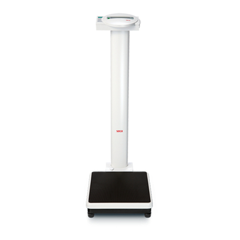
marsden M-100 User manual

USER MANUAL
M-100
Please take time to read these
instructions before starting
to use the scale
Version 1.0 07/06

Contents
Introduction 3
Product Specification 3
Safety Instructions 4
Explanation of Graphic Symbols 5
Power Supply and Low Battery 6
Operation: Basic Functions 7
Operation: Advanced Functions 9
Using the Scale with a Printer 13
Using the Scale with Bluetooth 14
EMC Guidance and Manufacturer’s Declaration 15
Recommended Separation Distance 17
Error Messages 18
Manufacturer’s Declaration of Conformity 19
Page 2

Thank you for purchasing a Marsden professional medical scale. This is a
precision Class III Weighing Instrument and considerate use will result in
many years of accurate weighing.
The scale has a maximum load capacity of 300kg which must not be
exceeded.
Product Specification
Model
M-100
Accuracy Class
Class III
Capacity/Division
300kg x 50g<150kg>100g
Weight of Scale
Approximately 16kg
Units of Measure
Kg
Function Keys
ON/OFF, HOLD, TARE, BMI, UNIT, 0-9
Stabilization Time
1-2 Seconds
Operating Temperature
0 to 40˚C
Power Supply
Rechargeable battery pack
6 x AA batteries*
12V 2AAC Adaptor
Indicator Display
2.5cm LCD display with 5 active digits
*contact Marsden for details
Page 3

Safety Instructions
Before putting the device into use, please read with care the information given in this user manual,
which contains important instructions for proper installation, use and maintenance of the device.
Marsden/the manufacturer shall not be liable for damages arising from failure to heed the following
instructions:
•When using electrical components under increased safety requirements, always comply with
appropriate regulations.
•Inappropriate installation/use will render the warranty null and void.
•Ensure the voltage marked on the power supply unit matches your mains supply.
•This device is designed for use indoors.
•Observe the permissible ambient temperatures for use.
•The device meets the requirements for electromagnetic capability. Do not exceed the
maximum values specified in the applicable standards.
•Batteries should be kept away from small children. If swallowed, promptly seek medical
assistance.
If you have any problems, contact Marsden/your local dealer/your service partner.
Cleaning
•We recommend using alcohol-based wipes or similar when cleaning the scale.
•Please do not use corrosive liquids, large amounts of water or high pressure washers.
•Always disconnect the scale from the mains power supply before cleaning.
Maintenance
•The scale does not require any routine maintenance. However, we recommend checking the
scale’s accuracy at regular intervals. If any inaccuracies occur, please contact your local
dealer or service partner.
Disposing of the Scale
•This product should not be treated as regular household waste, but should be handed in to an
electrical/electronic equipment recycling centre.
•You can obtain further details from your local council, your municipal waste disposal company
or from where you purchased the product.
Page 4

Explanation of Graphic Symbols
SN-21300100
Designation of the serial number of
every device.
(Number as an example)
“Please note the accompanying
documents” or “Observe operating
instructions”
Marsden Weighing Machine Group Ltd
Unit 1, Genesis Business Park,
Sheffield Road, Rotherham, S60 1DX
Identification of manufacturer of medical
product including address.
“Electro-medical appliance” with
attachment of type B.
Dispose of old appliances separately
from your household waste.
This product must be disposed of at a
communal collection point.
Carefully read this operation manual
before setup and commissioning, even
if you are already familiar with Marsden
scales.
Transport and storage temperature limit
indicating the upper and lower limit
(transport and storage temperature on
packaging).
Page 5

Power Supply & Low Battery
The indicator uses a rechargeable battery pack, or can be powered from the mains via the AC
adaptor.
Make sure the battery pack is installed in the battery box of the indicator. Alternatively, plug the AC
adaptor (12V 2A) into the port on the side of the indicator.
Installing & Replacing the Battery Pack
1. Take out the battery housing.
2. The rechargeable battery pack will slide into, or out of, the housing.
3. Check that the housing pin is connecting to the right point inside the indicator.
4. Place the housing back in the back of the indicator, and close the battery housing cover.
Optional battery
holder (to fit AA sized
batteries –contact
your dealer)
Page 6

Operation: Basic Functions
Switching on the Scale
Press the ON/OFF button firmly.
The scale will first test all of the display
segments.
The scale will now show its current
software version number.
The scale will now go into weighing mode
and should show 0.0kg on the display.
Page 7

Switching off the Scale
Press the ON/OFF button when the scale
is turned on. The scale will now power
down.
Setting the Scale to Zero
If for any reason the scale shows a
reading other than 0.0kg it can be reset to
zero.
Press the ZERO key once.
The scale will return to 0.0kg.
Page 8

Operation: Advanced Functions
Hold Function
Press the HOLD button once.
Allow the patient to stand on the scale.
After a few seconds the scale will lock on
the person’s weight. When the patient
leaves the scale, the weight will remain on
the display.
Press HOLD again to disable the Hold
function and return the scale to 0.0kg.
Page 9

Body Mass Index (BMI) Function
In normal mode, press the BMI key to
enter into BMI mode.
The display will show the last height
entered and the extreme left digit will
flash. Enter the height by using the
numeric keys. Press the ZERO key to
confirm the height. (NB: There will always
be an active flashing digit in the height
display, unless HOLD is pressed).
Weigh the patient as normal. The display
will show the weight, height and BMI
value. At this time, the weight and height
can be freely changed, and the BMI value
will be automatically calculated according
to the changed weight and height.
Press the BMI key to return to normal
weighing mode.
Page 10

Tare and Pre-Set Tare Functions
Press the TARE key for three seconds to
enter Preset Tare setting mode.
The display will show the last preset tare
entered and the extreme left digit will flash.
Enter the preset tare value by using the
numeric keys, then press the TARE key
again to confirm the value.
Press the ZERO key to return to normal
weighing mode.
To use the Tare function, add the item you
wish to tare off to the scale, and press the
TARE key. The display will show zero, and
then a minus number when the item is
removed from the scale.
Page 11

Setting the Date
Press the HOLD key for three seconds to access the time setting mode. The time
period digit that is flashing can be changed by entering the appropriate number from
the numeric key pad. The time period to be edited is selected by pressing the HOLD
key.
E.g. To input 25 December 2008, 8:00 a.m.:
Enter the year. Press HOLD to confirm
and access the date editing field.
Enter the date. E.g. “12.25” for
December 25th. Press HOLD to confirm
and access the time clock editing field.
Enter the time (24 hour clock only).
Press HOLD and the display shows:
YYYY→MM.DD→HH:SS
Press HOLD to return to normal
weighing mode.
Page 12

Using the Scale with a Printer
An optional Marsden external thermal printer (ModelTP-2100)is available for the M-100.
When the printerisfitted, the patient’s weight, height and BMI result can be printed.
Once the person has been weighed and their BMI calculated, simply press the PRINT key to
produce the following ticket:
Connecting the TP-2100 Thermal Printer
Plug the cable to the printer, and then connect its 9D connector to the indicator.
GROSS WEIGHT 60.00kg
TARE WEIGHT 30.00kg
NET WEIGHT 30.00kg
PATIENT HEIGHT 100.0cm
PATIENT B.M.I 37. 5
29/12/2008 17:00
Page 13

Using the Scale with Bluetooth
If your scale has Bluetooth connectivity, the universal Bluetooth symbol will be on the main
indicator display.
Bluetooth Connection
Long press the ZERO key for three seconds to enter the
Setting mode and then display the A-OFF menu.
Press the TARE key twice, and then press HOLD once to
enter the Bluetooth setting mode.
Using the HOLD key, select “ON” (enable) or “OFF” (disable).
Press the TARE key to confirm the setting.
Note: Disabling the Bluetooth function when not in use
will reduce battery power consumption.
Display the “bluEt” menu. Press the TARE key once.
Press the HOLD key to return to normal mode.
Search for the scale in your computer or device’s Bluetooth
settings (procedure may vary depending on device or system)
The scale will appear on the Bluetooth device list as
“MARSDEN BT”.
Connect your device to “MARSDEN BT”, and the scale is
ready to transmit data wirelessly via Bluetooth.
Page 14

EMC Guidance and Manufacturer’s Declaration
Guidance and manufacturer’s declaration –electromagnet emissions.
The M-100 is intended for use in the electromagnetic environment specified below. The customer or user of
this scale should ensure that it is used in such environment.
Emission Test
Compliance
Electromagnetic environment-
guidance
RF emissions
CISPR 11
Group 1
This scale uses RF energy only for
its internal function. Therefore, its
RF emissions are very low and not
likely to cause any interference in
nearby electronic equipment.
RF emissions
CISPR 11
Class B
This scale is suitable for use in all
establishments, including domestic
establishments and those directly
connected to the public low-
voltage power supply network that
supplies buildings used for
domestic purposes.
Harmonic emissions
IEC 61000-3-2
Class A
Voltage fluctuations/flicker
emissions
IEC 61000-3-3
Compliance
Guidance and manufacturer’s declaration –electromagnetic immunity.
The M-100 is intended for use in the electromagnetic environment specified below. The customer of the user
of this scale should ensure that it is used in such an environment.
Immunity Test
IEC 60601 Test Level
Compliance Level
Electromagnetic
Environment Guidance
Electrostatic discharge
(ESD)
IEC 61000-4-2
6 kV contact
8 kV air
6 kV contact
8 kV air
Floors should be wood, cement or
ceramic tile. If floors are covered
with synthetic material, the
relative humidity should be at
least 30%.
Electrical fast transient/burst
IEC 61000-4-4
2 kV for power supply
lines +1 kV for input/output
lines
2 kV for power supply
lines not applicable
Mains power quality should be
that of a typical commercial or
hospital environment.
Surge IEC 61000-4-5
1kV line(s) to line(s) 2
kV line(s) to earth
1 kV differential mode
not applicable
Mains power quality should be
that of a typical commercial or
hospital environment.
Voltage Dips, short
interruptions and voltage
variations on power supply
input lines IEC-6100-4-11
<5% UT (>95% dip in UT)
for 0.5 cycle 40% UT (60%
dip in UT) for 5 cycles 70%
UT (30% dip in UT) for 25
cycles <5% UT (>95% dip in
UT) for 5s
<5% UT (95% dip in UT) for
0.5 cycle 40% UT (60% dip
in UT) for 5 cycles 70% UT
(30% dip in UT) for 25
cycles <5% UT (>95% dip in
UT) for 5s
Mains power quality should be
that of a typical commercial or
hospital environment. If the user
of this scale requires continued
operation during power mains
interruptions, it is recommended
that this scale is powered from an
uninterruptable power supply or a
battery.
Power frequency (50/60 Hz)
magnetic field IEC 61000-4-
8
3 A/m
3 A/m
The scale’s power frequency
magnetic fields should be at
levels characteristic of a typical
location in a typical commercial or
hospital environment.
Note UT is the A.C mains voltage prior to application of the test level.
Page 15

Guidance and manufacturer’s declaration –electromagnetic immunity.
This scale is intended for use in the electromagnetic environment specified below. The customer of the user
of the scale should ensure that it is used in such an environment.
Immunity Test
IEC 60601 test level
Compliance level
Electromagnetic
environment-guidance
Conducted RF
IEC61000-4-6
Radiated RF
IEC 61000-4-3
3 Vrms
150 KHx to 80 MHz
3 V/m 80 MHz to 2,5
GHz
3 Vrms
3 V/m
Portable and mobile RF
communications equipment
should be used no closer to
any part of the scale including
cables, than the
recommended separation
distance calculated from the
equation applicable to the
frequency of the transmitter.
Recommended separation
distance:
d = 1,2 √P
d = 1,2 √P80MHz to 800 MHz
d = 2,3 √P800MHz to 2,5
GHz
Where P is the maximum
output power rating of the
transmitter in watts (w)
according to the transmitter
manufacturer and dis the
recommended separation
distance in meters (m).
Field strengths from fixed RF
transmitters, as determined by
an electromagnetic site
survey, should be less than
the compliance level in each
frequency range.
Interference may occur in the
vicinity of equipment marked
with the following symbol:
NOTE1 At 80 MHz and 800 MHz, the higher frequency range applies.
NOTE2 These guidelines may not apply in all situations. Electromagnetic propagation is affected by absorption
and reflection from structures, objects and people.
A) Field strengths from fixed transmitters, such as base stations for radio (cellular/cordless) telephones and
land mobile radios, amateur radio, AM and FM radio broadcast and TV broadcast cannot be predicted
theoretically with accuracy. To assess the electromagnetic environment due to fixed RF transmitters, an
electromagnetic site survey should be considered. If the measured field strength in the location in which
the scale is used exceeds the application RF compliance level above, the scale should be observed to
verify normal operation. If abnormal performance is observed, additional measures may be necessary,
such as re-orienting or relocating the scale.
B) Over the frequency range 150 kHz to 80 MHz, field strengths should be less than 3 V/m.
Page 16

Recommended separation distance between portable and mobile RF communications
equipment and the M-100.
This scale is intended for use in an electromagnetic environment in which radiated RF disturbances are
controlled. The customer or the user of the scale can help prevent electromagnetic interference by
maintaining a minimum distance between portable and mobile RF communications equipment (transmitters)
and the scale as recommended below, according to the maximum output power of the communications
equipment.
Rated maximum output
power of transmitter
W
Separation distance according to frequency of transmitter m
150 kHz to 80 MHz
d = 1,2√P
80 MHz to 800 MHz
d = 1,2√P
800 MHz to 2,5 GHz
d = 2,3√P
0.01
0.12
0.12
0.23
0.1
0.38
0.38
0.73
1
1.2
1.2
2.3
10
3.8
3.8
7.3
100
12
12
23
For transmitters rated at a maximum output power not listed above, the recommended separation distance d
in meters (m) can be estimated using the equation applicable to the frequency of the transmitter, where p is
the maximum output rating of the transmitter in watts (w) according to the transmitter manufacturer.
NOTE1) At 80 MHz and 800 MHz, the separation distance for the high frequency range applies.
NOTE2) These guidelines may not apply in all situations. Electromagnetic propagation is affected by
absorption and reflection from structures, objects and people.
Page 17

Error Messages
Low Battery
The scale’s alkaline AA type batteries are
flat; please replace the batteries.
Overload
This indicates that the scale’s load sensor(s)
have been overloaded. Reduce the loading
and retry.
Counting Error
1. The signal from the load cells is too
high. Please remove any weight from
the scale and try to power on again. If
the scale continues to show the error
message, it indicates a fault with the
electronics or wiring.
2. The signal from the load cells is too
low. Please remove any weight from
the scale and try again. If the scale
continues to show the error message,
it indicates a fault with the electronics
or wiring.
High/Low Zero Count
1. The scale is above its zero range.
Please remove any weight from the
scale and power on again. If the
scale continues to show the error
message, it indicates a fault with the
electronics.
2. The scale is below its zero range.
Check there is nothing jammed
underneath the scale and power on
again. If the scale continues to show
the error message, it indicates a fault
with the electronics.
EEPROM Error
This indicates there is a fault with the scale’s
software and is normally caused by a fault
with the load cell or wiring. Contact your
local service representative.
Page 18

Manufacturer’s Declaration of Conformity
Page 19
Marsden Weighing Machine Group,
Unit 1 Genesis Business Park,
Sheffield Road,
Rotherham,
South Yorkshire
S60 1DX

Tel: 01709 364296 / 0800 169 2775
Fax: 01709 364293
E-mail: sales@marsdengroup.co.uk
Manufacturing and Distribution:
Unit 7, Centurion Business Park,
Coggin Mill Way,
Rotherham,
S60 1FB
Head Office:
Unit 1, Genesis Business Park,
Sheffield Road,
Rotherham
S60 1DX
www.marsden-weighing.co.uk
Table of contents
Other marsden Scale manuals
marsden
marsden BS-250BT User manual
marsden
marsden M-65 Series User manual

marsden
marsden M-920 User manual
marsden
marsden Jadever JCO User manual
marsden
marsden V-25 User manual
marsden
marsden M-400 User manual

marsden
marsden M-650 User manual
marsden
marsden MBF-6000 User manual
marsden
marsden M-615 User manual
marsden
marsden IP 2101 User manual

marsden
marsden V-24 User manual

marsden
marsden M-400 User manual
marsden
marsden M300 User manual

marsden
marsden M-565 User manual
marsden
marsden MBF-6010 User manual
marsden
marsden M-545 User manual
marsden
marsden M-210 User manual
marsden
marsden V-110 User manual
marsden
marsden V-180 User manual
marsden
marsden M-110 User manual
