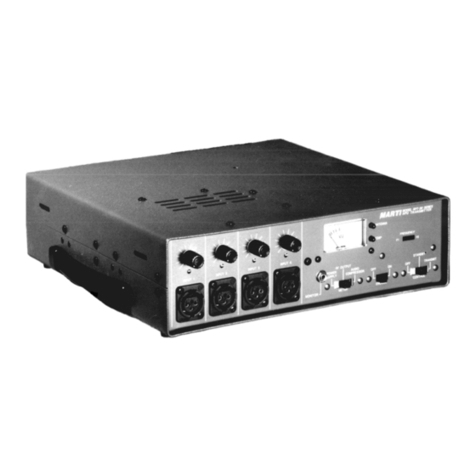
Marti STL-10 User manual

www.SteamPoweredRadio.Com
II
WARNING
THIS EQUIPMENT
MUST
BE OPERATED WITH A 3-PRONG
GROUNDED OUTLET RECEPTACLE. FAILURE TO USE A
PROPERLY GROUNDED OUTLET MAY RESULT IN IMPRO-
PER OPERATION
OR
SAFETY HAZARD!
LIMITED WARRANTY
The Seller warrants that, at the time
of
shipment, the
products manufactured by the Seller are free from
defects in material and workmanship. The Seller's
obligation under this warranty is limited to replace-
ment
or
repair
of
such products which are returned to
Marti at its factory, transportation prepaid and
properly insured, provided:
a.
Notice
of
the claimed defect
is
given to Marti
within
one
(l)
year [two (2) years for
SlL
systems]
from date
of
original shipment and goods are returned
in
accordance with Marti instructions.
b. Equipment, accessories, tubes and batteries not
manufactured
by
Marti are subject to only such ad-
justments as Marti may obtain from the supplier
thereof.
c. This warranty does not apply to equipment which
has been altered, improperly handled, or damaged
in
any way.
The Seller is in no event liable for consequential
damages, installation cost
or
other costs
of
any nature
as a result
of
the use
of
the products manufactured or
supplied by the Seller, whether used in accordance
with instructions or not.
This warranty is in lieu
of
all others, either expressed
or
implied.
No
representative is authorized to assume
for the Seller any other liability
in
connection with
Seller's products.
MAILING
&.
SHIPPING ADDRESS:
MARTI
Electronics, Inc.
P.O. Box
661
1501
N.
Main
St.
Cleburne, Texas 76031-0661
The United States of America
COPYRIGHT NOTICE
©1993 All Rights Reserved
Marti Electronics, Inc.
4th printing, January 1994
No part
of
this manual may be reproduced,
transmitted, transcribed, stored in a retrieval system ,
or
translated into any language, naturaJ
or
computer,
in any form
or
by
any means, without the prior
written permission
of
Marti Electronics, Inc.
Artwork depicting circuitry in this manual
is
protected
by
copyright Jaws.
Information in this manuaJ is subject to change
without notice and does not represent a commitment
on
the part
of
Marti Electronics, Inc.
Marti Electronics
may
make improvements and/or
changes in this manual or
in
the product described
herein at any time.
This product could include technical inaccuracies or
typographical errors.
PHONE NUMBERS:
Sales & Service
FAX (817) 645-9163
(817) 641-3869
11

www.SteamPoweredRadio.Com
Model STL-10
Broadcast Aural STL Transmitter
ISPECIFIGATIONS
Frequency range: 140-180
MHz
200-260MHz
280-340MHz
400-480MHz
500-960MHz
STL-10/150
STL-10/215
STL-10/300
STL-10/450
STL-10/950
RF poweroutput: (
+o
-.5 dB)
15
watts (140 -
480
MHz); 10 watts (500 -960
MHz)
Output
impedance:
50
ohms
Carrierfrequency ±.00025% (-20°C to +50°C)
stability:
Type
of
modulation: Direct
FM
Audio input: Balanced
600
ohms, +8 dBm, barrier strip.
BNC
co
nn
ec
tors
for unbalanced input
Subcarrier inputs: Two BNC connectors for remotecontrol and/or subcarrier in-
puts. 50-600 ohms unbalanced, 3
V.
P-P for 10% injection
Power
requirements: 120/220 VAC*, 50/60 Hz,
80
watts; 13.5 VDC
at
2.6
Am-
peres;
24
-28 VDC** at 2.6 Amperes
AC
powersupply: Precision, electronically regulated with current/temperature
limiting
Fuse: 2.5 AmpSlo-Blo for 115 V operation. 1.25 Amp Slo-Blo for
230 V operation. Type 3AG
Spuriousemissions: More than 60 dB below carrier
Automaticchangeover: Provision for automatic changeover by addition
of
ATS-15E
Automatic Switcher
Accessory connector:
15
pin D connector on rearpanel provides filtered access to
Remote Control, and Automatic Changeover,Remote
PowerMetering, and External
DC
Power
(Model UPS-12
Uninterrupti
bl
e Power Supply)
Metering: Precision "Peak-hold"
Bar
Graph Modulation
Meter
.
Illuminated RFWattmeter indicates Forward
Power
, Reverse
Power. TestMeter reads
PA
Current, SubcarrierLevel, 13.S
VoltSupply, and
RF
Drive 1,
RF
Drive2.
LED
indicates
Transmit.
Panel controls: Transmitswitch,
Test
Meter switch,
Power
Adjust pot
3

www.SteamPoweredRadio.Com
I
TABLE
of
CONTENTS
Introduction ..
..
......
..
......
..
.
..
......
..
....
..
....
..
.
..
....
..
....
....
....
..
..
..
.......
..
.
..
......
..
.
..
....
....
...........
..
.
..
.. 1
Specifications .................
..
...............
..
..................
..
.
..
.......
..
..........................
..
....
....
..........
..
3
Unpacking and Ins
pe
ction .....................................................................................
..
.......... 4
Installation
....
..
....
.
....
.
..
.
..
.
..
...
....
..
....
..
......
.
..
..
..
.
....
..
..
.
....
...
....
....
....
.
..
.
..
.
..
.
....
.
..
.
..
....
......
.
....
.
..
. 5
Electrical
Co
nnections ......................
..
..............................................................................
5
6
7
9
STLSystemBlock Diagram, No. 702-058 ........
..
....................................
..
......................
Antennas ...........................................................................................................................
Operation .......................................................................................................................
..
.
System Pe
rf
orman
ce
Te
sts.............................
..
.......................................
..
........................
11
Theory
of
Operation
..
.
..
.
..
.
....
..
....
.
..
.
..
.
..
....
..
........
..
.
..
.
..
....
..
..........
..
...
..
.
....
.
..
..
....
.
..
....
....
.
..
.... 12
FCC Emission Profile (500
KHz
Channel) Drawing........................................................
14
FCC Emission
Pr
ofile (200
KH
z
Channel) Drawing ........................................................
15
T
oo
ls andT
es
t Equipment Required................................................................................ 16
Transmitter
Te
st Report ..
..
..
..
..
..........
..
.........
..
....
..
.......
..
...............
..
.................
..
...
..
...........
17
Tune-Up and Adjustment ..................................................................................................
18
Block Diagram, No.
70
2-050, STL-10 .....................
..
................................
..
..................... 21
Adjustment Locations Diagram, No. 702-056,STL-10 ............................
..
...................... 21
Main Frame
AudioBoard
ModulatorBoard
Multiplier Board
Schematic, 7
02
-049-1
....
..
..
....
..........
....
..
....
....
.
..
.
......
....... 22
Parts List, 702-049-1
..
.....
....
..
....
...
..
....
..
..
....
....
..
.
..
.
......
..... 23
Schematic, 8
00
-194
..
.
....
.....
..
....
....
.
..
..
......
..
..
...
....
......
..
.
....
24
Parts List, 8
00
-194 .
....
.....
....
..
..
....
..........
..
......
...
..
..
....
.
......
25
Schematic, 800-195 .......................................................
..
27
Parts List, 800-195
......
.........
..
.....
..
.......
....
........
......
...
......
28
Schematic, 8
00
-163
....
..
..........
..
..
.
....
..
....
.
..
......
....
....
......
... 30
Parts List, 800-163
..
..
....
....
....
.
......
...
..
....
..
..
....
..
.
..........
..... 31
RF Power Amplifier Schematic, 800-170
....
......................................
..
...........
..
41
Board Parts List, 800-170
....
.................
..
................................... 42
Output Multiplier/ Schematic, 8
00
-045/046 .......................
..
......................... 47
Filter/Dir. Coupler Parts List, 800-045/046 ................................................... 48
Control Board
MeterBoard
Power Suppl
y/
Regulator Board
Input/Output Filter
Board
Schematic, 8
00
-
19
7
..
....
....
..
....
....
....
.
..
.
..
.............
......
.
..
...
..
50
Parts List, 8
00
-197 ...
....
..
....
..
......
..
..
...
..
.
....
.......
..
.
..
.
....
..
....
50
Schematic, 8
00
-284 .........................................................
51
Parts List, 800-284 .......................................................... 52
Schematic, 800-168, 800-168-1 ....................................
..
Parts
Li
st, 800-168, 800-168-1 ..........................
..
...........
Schematic, 8
00
-193-1
..
......................................
..
...........
Parts List, 800-193-1 ...............
..
...........
..
.........................
53
54
55
55

www.SteamPoweredRadio.Com
Features
of
the
STL-10
Transmitter
include:
• FCC
approved
under
Parts 74
and
94
•
User
selectable
aud
io
processing
provides
0,
25
,
50,
or
75
microsecond
pre-
emphasis
options
•
low-pa
ss
filters
designed
to
eliminate
overshoot
on
complex
audio
waveform
s
•
Calibrated
RF
watt
meter
for
forward
and
reflected
power
• Test
meter
on
front
panel
indicates
Subcarrier
level
,
Supply
Voltage,
PA
Current
,
RF
Dr
iv
er
1
and
RF
Driver
2.
Additional
test
points
are
located
ins
ide
transmitter.
• Twelve
segment
bar
graph
for
display
of
peak
transmitter
modulation.
The
five
highest
LED
's
(100%
to
250
%)
have
a "
peak-hold
"
feature
which
wi
ll
display
instantaneous
peak
value
for
one
second,
a
valuable
feature
when
dealing
with
pre-emphasized
program
audio.
•
Automatic
switching
capability
by
addition
of
Model
ATS-15E
Transmitter
Switcher
• Accessory
plug
for
external
DC
power,
remote
control
,
remote
metering
,
and
other
functions
• Low
power
consumption
for
operation
on
AC,
solar
cell,
battery
,
or
other
si
ngle-polarity
DC
source.
(Marti
Model
UPS-12
Uninterruptible
Power
System).
•
Terminal
strip
for
balanced
600
ohm
audio
input,
BNC jacks
for
unbalanced
audio
input,
Sub
1.
inp
ut,
Sub
2
input.
The Marti STL-
10
system derives its exce
ll
ence
fr
om Marti's experience in supplying
thousan
ds
of
such
sy
stems world-wide over the past thirty year
s.
This equipment incorporates
state-of-the-a.rt technology and is manufactured
in
modern, efficient facili
ti
es under high quality-
control standa
rd
s.
STL-10
Svstem
Specifications
Freq
Receiver
Range .
\l
uimum
.
\tuimum
IF
System Spccific
:it
i
ons
'.\IH
:i:
Tnnsmitter
Power Deviation Receiver Bandwid
th
Frequency Response Di
stortion
Noise
600-960 STL--101950 10
WQ
l!S
±
SO
KHz
R-101950 2
00
KHz
:0
.
.25
dB.
:?0
-15000
Hz
0.
25%
or l
ess
-80
dB
or bcner
400
.J8
0 STL-10/
-1
50
IS w:ins
::?5
KHz
R-10/450 125 KHz
:0
.25
dB.
20-15000
Hz
0.
30%
or less
•
15
dB
or bcncr
:!S
0-340 ST
L-10000
IS
w:ins
±15
KHz R-10/JOO
,~s
KHz
::0.
::S
dB.
20-15000 Hz 0.
301/e
or less •
•2
dB
or x
ncr
200-.260 STL-10/215
15
w
:111s
:15
KHz
R-10/21
S
t:?SKHz : 0.
:?5
dB,
20-15000
Hz
0.
3W
. or
less
-
i2
dB or 0<ncr
140-180 STL-10/150
15
w:
ms
:9
KHz
R
·I0/150
125
KHz
:0
.25
dB
.
20-1
S000
Hz 0.
30~~
or less -65
dB
or bcncr
System specificatio
ns
shown are
for
200
KHz
receiver IF bandwidth. Narrow band channe
ls
requiring 85 KHz IF bandwidth have ±0.25
dB
response, 0.3%
di
stonio
n.
System
Applications
Freq
B.W
.
R:ingc
FCC
Each
~nh
Aoolic:
11
ion
P:in
C
hannel
800-Y60
FM
S1e
rro
S
TL
74
200
KHz
B00-960
FM
S1creo S
TL
74
ISO
KHz
800-960
AM
Sicll:oSTL
74
IOO
KH:i:
92
8
-Q60
D:iu
or
B:ic
l:
trou
n~
~us1c
9-l 100
KH
z
92
8
-960
.i
,ch:inncl S;n.
P
2m
.
Fe
ed
94 100
KHz
Stereo System Oitterentlal Phase
0.5 d
egr
ees or less
Channd
Freouencv
RCSl)onsc
D
is
to
nlon
Noise
S
co:i
r.i
r
io
n
:0
.25
dB.
:o.1sooo
Hz
0.
254
or
less -
80
dB
or
bett
er
SO
dB
:0
.3 dB.
:?0-15000
Hz
0.3~
or less
•
72
dB
or bc
ucr
72 dB
:0
.3 dB.
2
0-
1
S
OOO
Hz
0.
3~
or
l
ess
.72
dB
or bcucr
72
dB
:0
.3
dB.
20-15000
Hz
I
0.
)
<;,
or less
•72 dB
Qr
bcu
er
72dB
:0
.3
dB.
20-15000
H
:i:
0.3"b or le
ss
•
70
dB
or
better iOdB
SPECIFlCA
TIONS
SUB
JE
CT
TO
CHANGE
WIT
HO
UT
NOTI
CE
2

www.SteamPoweredRadio.Com
Dimensions: 3.5 inches High x
19
inches
Wide
x
14
inches
Deep
8.89
cm
High x 48.26
cm
Wide x 35.56
cm
Deep
Weight:
Net
11
pounds. Domestic packed
18
pounds.
Net
4.9 kilograms. Expo
rt
pa
cked 8.2 kilograms.
RF
connector: UG-58 (type N female)
TypeAcceptance Number
FCC
ID: BEN9EZS1L-
10
/950
(FCC
Part94 &
Part
74):
• Voltage
must
bespecified with order.
••
Requir
es
APS-28/18 PowerSupply.
Specificationssubject
to
change without notice
!UNPACKING & INSPECTING
This
equipment
was
factory
tested,
inspected,
packed,
and delivered
to
the
carrier
with
utmost
care.
Do
not
accept
shipment
from
carrier
which
shows
damage
or
shortage
until
the
carrier's
agent
endorses a
statement
of
the
irregularity
on
the
face
of
the
carrier's
receipt.
Without
documen-
tary
evidence,
a
claim
cannot
be
filed
.
Unpack
equipment
immediately
up
-
on
receipt
and
thoroughly
inspect
for
concealed
damage
.
If
damage
is
dis-
covered,
stop
further
unpacking
and
request
immediate
inspection
by
lo-
4
cal
agent
of
carrier. A
written
report
of
the
agent's
findings
,
with
his
signature
is
necessary
to
support
claim
. Check
your
shipment
against
the
shipping papers
for
possible
shortage.
Do
not
discard
any
packing
material
until
all
items
are
accounted
for
.
Small
items
are
often
thrown
away
with
packing
material
.
Packing material should be retained
until
equipment
testing
is
completed.
Any
equipment
returned
to
the
factory
should be
packed
in
original
cartons,
insured,
and
pre-paid.

www.SteamPoweredRadio.Com
Ilnsta/latien
Install rack-mounted equipment
in
a well-ventilated, well-grounded, and
shielded
rack
cabinet. Do
not
locate
solid-stateequipment
in
a
rack
above
tube-type equipment
which
produces
high
temperatures.
Problems can
also
be
avoided
by
locating
this
unit
away
from
other
equipment
which
has transformers
that
produce
strong
magnetic fields.
These
fields
can
induce
hum
and
noise
into
the
Marti equipment
thus
Transmitter connections
(Refer
to
Drawing 702-058)
1.
Pr
og
r
am
audio output is
co
nnected to balanced
audio input screw terminals. Use shield
ed
wire.
Program audio level required is +8 dBm,
600
ohms
balanced and isolated from ground.
For
dual channel
ste
r
eo
repeat instructions
at
second transmitter. Audio
processing requirements wi
ll
be
discussed in
OPERATION.
2. Conn
ec
t a R
emo
te
Co
ntrol
or
Subcarrier
Generator (modulator) to the
jack
marked "J1 SUB
IN".
The
subcarrier
so
ur
ce
may
be
50
to
600
ohms
impedance, and the input le
ve
l required
is
approximately one (I) vo
lt
RMS. Subcarrier
frequencies may
be
between
39
KHz and
67
KHz.
Systems factory suppli
ed
with
200
KHz
IF
bandwidths will carry subcarriers up to
92
KH
z.
For
oth
er
subcarrier frequencies
or
narr
ow
IF
bandwidth
systems
co
ntact the factory. A second subcarri
er
ge
nerat
or
can
be
co
nnected to J3.
If
a duaJ channel
stereo STL is used
co
nn
ec
t
one
subcarrier
ge
nerat
or
to
JI
on eachchannel's transmitter.
3. The accessory conn
ec
tor has several uses such as
remote
co
ntrol, automatic
sw
it
chin
g,
and external
DC
power. Connection in
str
uc
ti
ons are furnished with
these accessories.
4. Connect
STL
transmitting antenna coax
to
"J6
ANTENNA
".
This requires a type N male
co
nnector.
5
reducing performance. Strong radio-
frequency (RF)
fields
should
be
avoided where possible. Extensive
shielding and
filtering
have been
incorporated Into this equipment
to
permit operation
in
moderate
RF
environments. All equipment racks,
cabinets, etc., should be bonded
together by wide copper grounding
strap to ensure that
all
system
elements are at
RF
ground potential.
A short flexible jumper (20" max.) may
be
used
be
tween J6
and
semi-flexible coax. Marti Part No.
585-017 double shielded, low-loss RG 2
14
/U
jumper
is recommended.
5.
For
dual channel stereo, use onJy
Marti
Part
No.
585-01
7,
20.5 inch double shielded
jumper
between
J6
of
each transmitter and the indicated
co
nnectors
of
the HRC-10
Se
ri
es
Co
mbine
rs
. Use a third
Part
No.
585-017
jumpe
r between the "ANTENNA"
co
nnect
or
of
the HRC-10 and the semi-rigid coax. Refer to
Drawing 702-058.
6.
Tum
transmitter off. Connect
AC
line receptacle
on
back
of
the transmitt
er
to a 115 volt
AC
power
so
ur
ce
with special
co
rd
set
sup
plied. USE
ONLY
3-
PRONG
GROUNDED OUTLET RECEPTA-
CLES
FOR
SAFETY.
WARNING
This
equipment
must
be
operated
with a
3-prong,
grounded,
115
volt,
AC
outlet
receptacle! Failure
to
use
a
properly
grounded
outlet
could
result
In a
safety
hazard
or
faulty
equipment
performance!

www.SteamPoweredRadio.Com
LETT
PROGRAM
IN
41
AGC/LIMJTER
LEFT
PROGRAM
SUB
AUOIO
IN
41
AGC/LIMITER
zo
·
JUtf'ER
RG
21'1/U
LErT
TRANSMITTER
zo
·
JUKPER
RS
Zl'I/U
585-017
LEFT
AUO
JO
OUT
TO
STEREO
GENERATOR
LErT
RECEIVER
S 585-017
L'l'IW~
rL'l'IW
s 1 r R-10
RECEIVER
JG
J3
3 '
RG-58
CABLE
I
3 '
RG
-
!58
CABLE
I
SUB
AUDIO
OUT
JI
w © LOr'l-50 LOf'l-50 1
__!!.L___,
1'
SCG·
10
I
HRC
~-----'
►
">-'
!(
).
:I
~
SUBCARRIER
GENERATOR
10
L'l'IN
CONNECTOR
L'l'IN
CONICCTOR
!
SUBCARRIER
OEl100ULATOR
TO
STEREO
GENERATOR
RI
GHT
PROGRAM
IN
4(
AGC/LlMITER
J L
RIGHT
AUDIO
OUT
RIGHT
TRANSMITTER
RIGHT
RECEIVER
1 1
SJT
1
L-
lO
JS
r
~
J~-10
RECEIVER
,,.I
I
MARTI
CLEBURNE,
TX
3'
RG-58
CABLE
,~
TC-8/67
KHZ
REMOTE
CONTROL
CR·
10
TSL
RECEIVER
STUDIO
FM
TRANSMITTER
SITE
3'
RG-58
CABLE
'°
TC-8/67
KHZ
REl10TE
CONTROL
METERING
SAMPLES
l
lP
-8
RELAY
PANE"~
TM
OUT
TSL·15
OR
SUB
G£N£RATOR
CON
T
ROL
COMMANDS
FOR
DETAILED
INSTRUCTIONS
READ
EQUIPMENT
INSTRUCTION
MANUALS
DRAWING
NO
.
TITLE
ELECTRONICS
COPYRIGHT
702-058
STEREO
STL
SYSTEM
BLOCK
DIAGRAM
76033-0661 06-
JAN-9'1

www.SteamPoweredRadio.Com
!ANTENNAS
The
followingsuggestions are o
ff
ered to
he
lp those
responsible for antenna installations avoid costly
er
rorsin assembly and adjustment. Marti Electronics,
Inc. assumes no responsibility
for
the installation and
performance
of
antenna systems associated with
its
equipment. The following suggestions are notintended
to be a complete step-by-step procedure, simply a
listing
of
so
me of the m
ost
frequ
en
tly reported errors
in antenna system installation.
Antenna Assembly
Fo
ll
ow
the manufacturer's instructions carefully. If
no instructions were included with the ant
en
na,
ca
ll or
write the antenna manufacturer for instructions. Errors
are frequently made in assembly
of
the
RF
feed dipole
elements which must be installed in
th
e same plan as the
reflector grids. ln other words,
if
the reflector grid
elements are horizontal, then the feed dipole elements
must also
be
horizontal. Cross polarization
of
grid and
feed dipole will result in total loss
of
antenna gain
!.
Transmission Line Connector Assembly
Do not u
se
RG-58 U
or
RG-8 U cable for
STL
station
antennas! They have t
oo
much loss at
VHF
and UHF
frequencies. Follow the instructions furnished by the
manufactur
er
wh
en
cutting coaxial
cab
le. Inspect the
ca
ble ends for small metal fragments which can short-
circuit the line inside the connector assembly. Che
ck
the
line for a sh
or
t-c
ir
cuit
co
ndition after each connector is
install
ed
by using an ohmmeter. Pressurized line should
be checked for several days under pressu
re
before instal-
lation on a tower to ensure that
th
ere
are
no leaks in the
line or fittings
Moisture Proofing Coax Connectors and
Fittings
Ex
tr
eme care must be
exe
rcised with coaxial cable
before and after
co
nn
ec
tors have been installed to ensure
th
at
moisture does n
ot
e
nt
er the line. Foam dielectric line
can
ta
ke on moisture ab
so
rption which is difficult
to
detect and remedy.
Th
erefor
e,
k
eep
the line
dry
while in
storage with ends tightly capped. Coaxial splices,
co
nnec-
tors, and fittings, to be located outside should
be
made
mechanically tight, then
coa
t
ed
with a weather-proofing
material over at l
eas
t two layers
of
vi
nyl plastic electrical
tape. Moisture problems in antenna systems are usually
traced back
to
connectors which have
NOT
been properly
taped.
Th
e Marti
K-1
Grounding and W
ea
therproofing Kit
is recommended for u
se
in each new antenna in
stal
lation.
7
Location and Grounding of
Coa
xial Ca-
ble
Keep the
STL
receiver coaxial
ca
ble
as
far from the
broadcast transmitter and its coaxial
cab
le
as
possible.
DO
NOT
STRAP
RECEIVER
CABLE
TO
THE
MAIN
ANTENNA
CABLE
AT
ANY
POINT.
PLACE
THE
RECEIVER
ANTENNA
COAXIAL
CABLE
ON
THE
OPPOS
I
TE
SIDE
OF
THE
TOWER
FROM
THE
MAIN
ANTENNA
CABLE
. Maintain maximum separa-
tion between these
ca
bles at all points, including the dis-
tance from tower base to transmitter building
as
we
ll
as
inside the building.
System Groundi
ng
It is essential that the
STL
antenna system be properly
grounded for safety and proper operation.
Antenna Installation and Adjustment
The
polarization
of
the transmit and receive antennas
of the
STL
system must
be
the same! This means that
if
th
e transmitting antenna is h
or
izontal, the receiving
antenna must also be horizonta
l.
Each antenna should be
attached to the tower to allow for final adjustme
nt
in
azimuth heading and vertical tilt. After visual adjustment
of
th
e antennas, the transmitter and receiver can be used to
make the final adjustments
of
the antennas. With the
transmitter driving one antenna,
th
e receiver antenna is
adjusted for maximum signal (indicated on the receiver) in
both horizontal and vertical directivity. CAUTION:
Antennas have a "major" and
se
veral "minor" lobes in
th
ei
r directivity patterns. A common error is
to
peak
th
e
antenna on a minor lobe, resulting in a signal level
of
o
nl
y
a fraction
of
the major lobe signal. This e
rr
or
can be
avoided o
nl
y by swinging
the
antenna through a lar
ge
angle so that all lobes are evaluated and the major lobe
clearly determined. After one antenna is adjusted, the
transmitter and receiver l
oca
tions are r
eve
rsed, to allow
adjustment
of
th
e
ot
h
er
antenna.
If
an
RF
wattrneter is
ava
il
able, each antenna and transmission line
ca
n
be
ch
ec
ked for
VS
WR
when the transmitter is supplying
power
to
it. The
VSWR
should be less than 1.5 to 1
(
1.
5:l
).
IF
THE ANTENNA SYSTEM FAILS TO
GIVE THE PREDICTED SIGNAL STRENGTH
LEVEL, THE FOLLOWING ITEMS SHOULD BE
CHECKED:
1. Check for
co
rrectassembly
of
antenna.
2.
Check that antennas have same polarity.
3. Check orientation
of
antennas in both horizontal and
vertical directions.

www.SteamPoweredRadio.Com
4. Check VSWR
of
both transmitand receive antennas.
VSWR should
be
less that 1.5:
1.
5. CheckFresnel zoneclearance along radio path.
6. Check for obstructions in the path such as trees and
man-made structures. Do
NOT
depend on maps or
aerial photographs.
8
CAUTION & WARNING
You CAN
BE
KILLED
IF
AN ANTENNA COMES
IN
CONTACT WITH ELECTRIC POWER LINES OR
EXPOSED ELECTRICAL WIRING.
FOR
YOUR
SAFETY USE EXTREME CAUTION WHEN
INSTALLING ANTENNAS.
KEEP
AWAY FROM
POWERLINES.

www.SteamPoweredRadio.Com
Transmit-Off Switch & LED
This
toggle switch controls the
RF
output
of
the
transmitter.
The
red
LED
above this switch is a visual
indication that the switch is in "
TRANSMIT
"
pos
it
ion.
The
audio
circuits, the 13.5 volt regulated
power
sup
ply and the meter illumination lamps
remain
on
when the
TRANSMIT
switch is "OFF
".
Forward-Reflected Switch &
RF Power Meter
The
RF
POWER
METE
R, with its
se
lector
switch, allows monitoring paramet
ers
within the
transmitter
as
fo
llows:
1.
When swit
che
d to "
FORWARD
POWER
",
the
meter indicates the RF power outp
ut
of
the STL-10
transmitter.
The
maximum power
is
10
Watts (9
Watts nominal) for the 890-960
MHz
(United States)
band and 15 Watts for all other (export) frequencies.
2. When switched
to
"REFLECTED POWER", the
TEST
METER
indicates the
amo
un
t
of
power
returning on the coaxial line from the
ant
en
na
.
Th
is
is
useful in determining the
VSWR
(Vo
lta
ge
Standing
Wave
Ratio) for
the
antenna system.
The
lower the
VSWR
for a gi
ve
n forward power, the better. Most
antennas guaran
tee
a
VSWR
of
less than 1
.5
to
I.
The
table
be
l
ow
gives
VSWR
for various reflected
powers:
Forward Reflected
Power Power VSWR
10
Watts (890-960
MHz
) 0.3 watts 1.40
10
Watts (890·960MHz)
0.4
watts 1.50
10
Watts (890-960 MHz) 0.5 watts 1.57
10
Watts (890-960 MHz) 0.7
watt
s 1.70
10Watts (8
90
-960 MH
z)
1
.0
wa
tts 1.90
15 watts (140-4
80
MHz) 0.3 watts
1.
35
15 watts (140-4
80
MH
z)
0.4
watts 1.40
15 watts (140-480 MHz) 0.5 watts 1.45
15
watts (140-480 MHz) 0.7 watts 1.55
15 watts (140-480MHz) 1
.0
watts 1.70
9
Peak Modulation Meter
A ''peak-hold" twelve
segme
nt bar graph
displ
ay
is included
on
the
STL-10
transmitter for
setting and monitoring peak
STL
m
od
ulation
(composite or mono
mode
).
The
five high
est
LED'
s
(100%
to
250%) have a "peak-hold" f
ea
ture which
will
display an instantaneous peak value
for
one
second. This is a valuable
featu
re when dealing with
pr
e-emp
hasized program audio.
The
procedure
fo
r
setting peak modulation
is
to
adjust
audio input level
into the
STL-10
until the
100
%
bar
is flashing on
audio peaks.
The
110% through
250%
bars
indi
ca
te
over-modulation and require a reduction in input
level to obtain a 100% peak indication.
Test Meter
The
TEST
METER
with its selector
sw
itch,
all
ows
monitoring
of
five important parameters within
the transmitter
as
fo
llows:
I. "
SUB
LEVEL
" -Indi
ca
t
es
subcarrier injection. 0
VU
is
approximately
20%
inj
ectio
n.
For
10%
injection use -6 VU. Subcarrier voltage
at
Jl
or
J3 is
approximately l volt
for
20%
injection, 0.5
vo
lts for
10%.
2. "
+13
VOLT
SUPPLY" -Indicates regulated
volta
ge
supply operation. +1.5
VU
is
app
roximately
13.5
voe
.
3. "P.A. CURRENT" -
The
co
llector
curre
nt
of
the
final amplifier
an
d its driver is
ca
librated
to
r
ead
"O
VU"
on
the
meter
at rated
powe
r outp
ut
and
efficiency.
The
POWER ADJUST
pote
ntiometer
should never
be
set
to
produce a P.A. current greater
th
an
0
VU
.
4.
"
RF
DR
IVE
1"
-
The
RF drive level
at
TP-4
of
MULTIPLIER,
800-
163.
5. "
RF
DRIVE
2" ·
The
RF
drive level
at
TP-5
of
MULTIPLIER, 800-163.

www.SteamPoweredRadio.Com
Pre-Emphasis Selection
Two
pr
ogr
ammable switches,
Sl
and
S2
, on 800-
194 Audio Board, enable
the
user to
se
l
ec
t Oµ
s,
25
µs,
50
µ
s,
or
75
µs pre-emphasis characteristics.
The
selection
of
one
of
the
se
options in the transmitter
requires a
co
rresponding
se
lection
of
S1 and
S2
on
the receiver (R-10) Audio Processing Board, 800-
205. Refer to STL-10 Drawing 702-056 and R-10
Drawing
702
-057 for the location
of
these switches.
The
sw
it
ches as shown in
the
diagrams, are
positioned for
75
µs at the factory.
75
µs pre-
emphasis
and
de-emphasis produces the best
threshold noise performance in an
FM
system.
It
doe
s, however,
pr
esent problems in modulation
co
ntrol.
Some
users, therefore, may wish to u
se
50
µs,
25 µ
s,
or
flat processing.
AM
stations will find flat
pr
ocessing desirable sin
ce
the
STL
can be treated
as
a
pair
of
wires in
pr
oof-of-
perf
ormance tests without
possible overmodulation
of
the link at high
10
audio frequencies. With 75 µs pre-emphasis, audio
input levels to the transmitter should be redu
ced
20
dB below 100% modulation when running frequency
response tests
to
prevent overrnodulation
at
the
higher
audio fre
qu
encies. With a full-quieting
RF
signal into
the receiver
(0
µs
de-emphasis), 0
µs
pre-emphasis
will produce a system signal-to-noise ratio
approximately 6 dB less than
75
µs pre-emphasis.
Received signal levels less than full quieting may
produce a differen
ce
of
as much as 13 dB between
flat and
75
µs pre-emphasis.
Frequency Measurement
The
RF
output frequency
of
this transmitter should
be measured a
nd
adjusted
as
often as necessary to
insure on-frequency
ope
ration
and
to
co
mply with
r
egu
l
at
ions. This procedure
is
cover
ed
in the
TUNE
UP
and ADJUSTMENTsection.

www.SteamPoweredRadio.Com
!system
Perlormance Tests
The
STL-10 transmitter, R
-10
receiver with the
associated a
nt
enna system can
be
tested and com-
pared with factory test data included in this manual.
Th
e foll
ow
ing
pr
ocedures should
be
followed in ord
er
to obtain reliable and accurate results.
Before audio tests
or
subcarrier tests are begun
check the receiver
"S
IG. LEVEL"
METER
for
required minimum signal. A
co
nversion
fr
om
VU
to
microvolts
is
given und
er
OPERATION in the R-10
receiver manual.
For
a
950
MHz.
system using
50
KHz
FM
deviation, typical noise levels
are:
1 µv for
20
dB SIN ratio
3 µv for
50
dB SIN·ratio
10
µv
for60dB SIN ratio
20 µv for70dB SIN ratio
50+
µv for ultimate SIN ratio
For
the above system with 20%
subca
rrier
in
ject
ion, the following noise level
on
the subcarrier
(Marti SCG-10-
SC
D-10 System) was measured: (no
moduJation main
or
sub)
10 µv
20
µv
30
µv
1
50
µv
for
40
dB Subcarrier SIN ratio
for
47
dB Subcarrier SIN ratio
for
50
dB Subcarrier SIN ratio
for ultimateSubcarri
er
SIN ratio
With ultimate SIN ratio, main
to
s
ub
crossta
lk
sh
ou
ld
be
-40 to -45 dB (u
si
ng Marti
SCG-10
-
SCD-
10Subcarrier System).
NOISE
Noise measurements
sho
uld
be
made first, since
high noi
se
levels wi
ll
influence distortion readings.
Al
so
ground loops in the audio oscillator to
transmitter
co
nn
ec
tions and
di
stortion analyzer to
receiver connections must
be
resolved before testing
begins.
The
influence
of
high
RF
fields upon the test
equipment mu
st
be
determined and corrected before
accurate measurements
can
be
made. NOTE:
NO
I
SE
AND DISTORTION MEASUREMENTS
ARE
MADE
WITH
SUBCARRJER AND REMOTE
CONTROL
INPUT
SIGNALS REMOVED. System
signal to noise ratio
is
determin
ed
while modulating
the transmitt
er
100% at
400
Hz. A level
of
+8 dBm
across the
ha
.lanced audio input terminals
of
TB-1
IL
will
pr
od
u
ce
a reading
of
I
00%
modulation
on
the
"PEAK
MOD
ULATION" indicator.
Set
Receiver
"PGM
LEVEL
ADI"
pot
for +
IO
dBm
output into the
di
sto
rt
ion
ana
lyzer. If the distortion analyzer has a
high impedance input,
add
a
600
ohm load resistor
to
mat
ch the receiver. Establish +10
dBm
on the audio
voltm
eter
of
the analyzer as the r
efe
r
ence
l
eve
l for
I
00%
modulation.
Next
, remove the audio signal
from the transmitter input
an
d measure noise level
below reference (100% modulation). This reading
should
co
mpare with that published und
er
SYSTEM
SPECIFICATIONS in this manual.
DISTORTION
Harmonic distortion is u
sua
ll
y measured at 100%
modulation and
at
several frequencies.
If
pre-em-
phasis processing
is
used in the transmitter with
co
r-
responding de-emphasis in the receiver, it
is
normal
for available au
dio
level
at
the receiver to drop with
increasing frequency according to the de-emphasis
cu
r
ve
selected. At 15
KHz,
there is suffi
cie
nt level to
operate most modern distortion analyzers. Distortion
levels should
be
within specifications.
If
distortion is
out
of
specs, che
ck
system noise, ch
ec
k for test
equi
pme
nt ground loops, RFI, and transmit-
ter/receiver
ope
rating frequency.
If
either unit is
off
frequency, the
FM
modulation sidebands are not
ce
ntered within the·
IF
filter bandpass, whi
ch
can
cause audio distortion.
FREQUENCY RESPONSE
If
the
STL-
10 System
is
switched to flat
processing, frequency response can be measured as if
the signal were being sent over straight wires.
If
pre-
emphasis processing is used (especially
75
µs)
allowance must
be
made in the transmitter a
ud
io
input
level to prevent over-modulation at test frequencies
above
400
Hz.
The
simplest and fast
est
method is
to
set
the transmitter audio input level for 1
00%
modulation at
400
Hz., then attenuate trus level
20
dB.
Set
receiver output level
to
-10
dBm
as t
he
ref
erence, th
en
sweep the audio band for response.
Response should
be
within limits published in the
SYSTEM SPECIFICATIONS.

www.SteamPoweredRadio.Com
OF-OP;
Refer to Block Diagram Drawing No. 702-097 and appropriate Schematic
Diagrams.
POWER SUPPLY, 800-168
and 800-168-1
Board
800-168 contains a br
idge
rectifier
(D
1 -
4), fil
ter
capaci
t
or
C5, and voltage adjust pot R2, and
reverse
po
larity protection diodes
D5,
D6,
and
D7
.
The
unregulated output voltage
of
this
supp
ly is 17 -
20 volts. Series regulator
IC-
1
is
located on the large
heat sink
at
the r
ear
of
the transmitter, and
sup
plies
13.5 volts
DC
at
5 amps.
INPUT OUTPUT FILTERS,
800-193A
AJI
input/
outp
ut
circuits connected
to
ACCESSORY
con
nector
J4
,
as
well
as
the
AC
line
input, have radio-frequen
cy
fil~
rs.
CONTROL BOARD, 800-197
Switchin
g,
interfacing, remote metering and
control functions
are
available at the 10-pin
co
nn
ector
of
the control board. Since the + 13.5 volt
DC
supply
is
on
co
ntinually when the
S1L-
l0
is
plugged into the
120
volt
AC
source, the transmitter
RF
power output
is controlled
by
pl
acing
sw
itch S3 in the
emit
ter
ci
rcuit
of
the
first stage
of
MULTIPLIER, 800-163.
This
co
ntrol function
is
also available
at
pin 15
of
Accessory
Connec
t
or
J4.
Transistor Q l isolates the
"FOR
WARD
POWER"
METER
samp
le from the remote meter terminal (pin
13
ofJ4).
Automatic
swi
tching between two
S1L-
I0
transmitters
is
accompli
shed
by
use
of
the optional
ATS-
1
5E
Automatic Transmitter Switcher. Consult
the
factory
or
Marti
catalog for additional
information.
AUDIO BOARD, 800-194
The 600
ohm
balanced
audio
input
to
the
transmitter is
co
nn
ected to the inputs
of
a unity gain
differential amplifier
IC-IA.
A potentiometer,
R9,
is
provided
fo
r adjusting the amplifier
to
produce the
12
maximum
commo
n
mode
rejection (CMR).
The
output
of
the differential amplifier is direct-coupled
to
the pre-emphasis amplifier and has two
ca
pa
citors
se
l
ec
ted by switches Sl and S2, which provide
options
of
0,
25,
50
or
75
microseconds
pre
-
emphasis. Following the pre-emphasis circuit
are
tw
o
stages
of
active Butterworth low-pass filtering.
The
signal then is fed
to
the
MODULATOR
audio
input
and to metering amplifiers IC3A a
nd
IC3B.
The
subcarrier input is routed to the
MODULATOR
subcarrier input.
MODULATOR, 800-195
The
MODULA
TOR
cons
ists
of
a voltage-
co
ntr
olled crystal oscillator
Q2,
buffer amplifier Q3,
subcarrier modul
ato
r D2, precision voltage regulator
ICI and
ove
n heater
co
ntr
ol
Ql.
Pr
ec
i
se
frequency
control is obtain
ed
by thermally coupli
ng
components
Yl,
Ql,
Q2,
and
ICI
to the tempe.rature regulated
Frequency Control
Modu
le, 800-160-
l.
Coarse
and
fine frequency adjustment
is
provided
by LI and
L2
while main channel modulation is
provided
by
a voltage variable capacitance
diode
in
the Frequ
ency
Control Module.
Bias
for
this
diode
is
obtained through voltage divider resistors R4,
R5
,
and R7.
Diode
D1 temperature compensates the bias
supp
ly. Components
L3,
Cl3,
and
D2
permit
phase
modulation
of
the
subcarrier information upon
the
RF
output
of
transistor
Q3
.
MULTIPLIER BOARD, 800-
163
The
modulator
RF
out
put is frequency-multiplied
in the multipli
er
board
to
obtain the various operating
frequencies listed
on
the
S1L-
IOspecification sheet.
The
multiplication factor for various frequency
bands is as follows:
140
-180MHz
12
X
200-
260
MHz
16
X
280
-
340
MHz
24
X
400
-
480
MHz
24 X
500
-
960
Mhz
24
x•

www.SteamPoweredRadio.Com
*Power varactor doubl
er
brings total multipli-
cation
to
48
X.
The
power level at the input
to
the multiplier is
·approximately 5 mw. and the output l
eve
l is 0.7 to 1.2
watts.
RF POWER AMPLIFIER,
800
-1
70
RF
output
of
the MULTIPLIER BOARD is
connected
to
the input
of
the power amplifier board
at
a
50
ohm
impedance. Transformation
of
the
50
ohm
input to the base impedance
of
QI is accomplished by
Cl,
C2, and
Ll.
Ll,
Ll2,
and
Rl
provide a path for
QI base current and
th
e L12 -
Rl
parallel circuit
reduces low frequency gain and instability.
The
RF
output power
of
QI is approximately 4 watts and is
fed
to
the base
of
Q2
by
the
L-C impedance matching
network shown on the schematic. L13 and R2 reduce
low frequency
ga
in and instabi
li
ty.
RF
power
at
the
co
ll
ector
of
Q2
is matched to
50
ohms by the L-C
network shown.
The
co
ll
ectorsupply
to
QI and
Q2
is
de-coupled by
lA
and C7 -
12
.
OUTPUT LOW-PASS FIL-
TER, DIRECTIONAL
COUPLER, 700-046
On
frequencies
be
l
ow
480
MHz
.,
RF
output from
the
RF
POWER AMPLIFIER passes through a four-
section low-pass filter and directional
co
upler before
reaching
the
output
co
nnect
or
16
.
The
directional
coupler is
of
microstrip construction.
13
OUTPUT LOW-PASS FIL-
TER, VARACTOR DOUB-
LER, DIRECTIONAL COUP-
LER, 700-045
In the 500-960
MHz
band the
RF
output
of
the
POWER AMPLIFIER (15 watts) is appli
ed
to
a
power varactor diode (D3 in Drawing 700-045)
w
hi
ch generat
es
harmonic energy for frequency
multiplication.
lA
and
C7
are tuned
to
the second
harmonic
of
the input frequency. This
RF
power is
co
upled to two additional bandpass filters (L3 -C6
and L2 -C5). L2 is tapped at the
50
ohm point
to
feed
a directional
co
upler w
hi
ch is
co
nnected to output
co
nnector
16.
DUAL LINK STEREO
STL
Two STL-10 Links can share the same
500
KHz,
300
KH
z,
or
200
KHz
channel for transmission
of
left
and
ri
ght ster
eo
co
mponents, as shown in the
STEREO STL SYSTEM BLOCK DIAGRAM,
Drawing No. 702-058. A system operating in this
manner uses no more spectrum (and possibly less)
than "COMPOSITE" systems, while
pr
ovid
ing
much
lower channel cross-talk (72 dB). Sin
ce
the two links
are independent, if one
li
nk fails, continued operation
in mono service is assured. Phase shift between
channels can
be
less than 1degree.
The two carriers are offset above and below the
channel center frequency as shown in the following
FCC EMISSION PROFILE Drawings. Offsets are
125
KHz
for
500
KHz channels,
75
KHz for
300
KHz
channels, and
50
KHz
for
200
KHz channels.
Using a Marti HRC-10 Transmitter Combiner having
40
dB isolation, all sidebands and
IM
products are
well within the limits
of
Subpart E
of
FCC Rules Part
74.535. Optional transmitter combiners are available
which provide
70
dB
or
l
00
dB
of
isolation. Receiver
IF
se
lectivity required in this system is
200
KHz for
500
KHz
channels, 85 KHz for
300
KHz channels
and
75
KHz for 200
KH
z channels.
Another advantage of the STL-10 Stereo System
is the fact that it will deliver a higher signal to noise
ratio than a
"co
mposite" while req
umn
g
approximately one-tenth the receiver signal l
eve
l
of
a
"composite."

www.SteamPoweredRadio.Com
Distortion Analyzer
Oscillator
Attenuator Set
Frequency Counter
Digital Multimeter
Analog Multimeter
RF
Attenuator
RF Signal Generator
SpectrumAnalyz
er
Wattmeter (
50
ohm
s impedance)
25 watt element
Automatic Modulation Meter
50
watt
RF
Load
Krohn-Hite Model 6801
Krohn-Hite Model 4500
Hewlett-Packard Model 3500
Hewlett-Packard Model 5383A
(option 001)
Beckman Model 3030
Triplett Model 630
Kay Model 437A (adjustable 0-110 dB)
Marconi Model 2022C
Hewlett-Packard Model 8558B
Bird Model 43
100-250 MHz., 250-500 MHz.,
or
400-
1000
MHz.
Bird
Wavetek Model 4101
Microwave Associates Model 44003
ITOOLS for ALIGNMENT
Type
of
Tool Manufacturer's No. Marti Part No.
Tuning Tool
GC9300
930
-037
TuningTool
GC
9440
930
-069
TuningTool Spectrol
8TOOO
930-100
TuningTool Sprague-Goodman 930-062
16
I

www.SteamPoweredRadio.Com
ITRANSMIITER TESTREPORT
Customer:
-------------------------
Address:
-------------------------
STL-10Serial#:
_______
Frequency:
_______
_
Test Point Readings
TP-1: 0.15 volts DC -0.60 volts DC
TP-2: 0
.7
0 volts DC -1.90 volts DC
TP-3: 0.50 volts DC -1.00 volts DC
TP-4: 0.50volts DC -1.90 volts DC
Test Meter Readings
Subcarrier Level: 0 VU = 20%
+13 volt Supply:
+1
VU=
13.5 volts DC
P.A. Current: 0 VU = Normal
RF Drive
1:
-2 VU to
+3
VU
RFDrive
2:
-2 VU to
+3
VU
Total DC Current:
Modulator Bias:
100% Modulation is: ±
__________
KHz.
Test Equipment
Frequency Counter,
HP
Model 5383A
Deviation Monitor, Wavetek4101
17
Date
Signature

www.SteamPoweredRadio.Com
ITlllf&-UP
and
ADJUB
J'
MENTS
Refer
to
Location of Adjustments Drawing No. 702-098 and appropriate schematic
diagrams for each module.
POWER SUPPLV BOARD, 800-
168
1.
Remove Dummy Load to RF output 16. Remove top
cover
of
transmitter. Connect the positive lead
of
a 0-20
volt
DC,
digital voltmeter
of
0.2% accuracy
(o
r better) to
a connector pin with a red wire on POWER SUPPLY
BOARD, 800-168. Connect negative lead to chassis
ground.
2.
Pl
ace
CONTROL switch in "TRANSMIT' position
and adjust
R2
for 1
3.5
volts, DC.
MODULATOR BOARD, 800-195
Connect dummy load with .sampling attenuator
to
ANTENNA connector
16
of
transmitter. Connect an
accurate standard FM deviation meter and frequency
counter
to
sampling attenuator
or
15
FREQUENCY
TEST
JACK. Place CONTROL switch in "TRANSMIT"
position.
1.
Measure bias voltage at TP (test point)
of
MODULATOR BOARD, 800-195 using digital
DC
voltmet
er
.
This
voltage should
be
that recorded on
STI..
-
10 TRANSMITTER TEST REPORT.
To
en
sure low
distortion modulation,
DO
NOT CHANGE TIUS
VOLTAGE SETTING.
2. Set transmitter onfrequency by adjusting
L2
(fine) coil
slug using correct insulated tool.
If
necessary,
Ll
(coarse
adjustment)
can
be made using the insulated tool
specified.
3. Feed a
400
Hz. +8 dBm signal from an audio signal
generator into TB-1.
The
PEAK MODULATION meter
should read
"100
%. This was set at the factory and should
not require field adjustment. If an accurate
FM
mod
ul
ation meter is available, adjust R24 (modulation
meter
ca
libr
ate
) on AUDIO BOARD, 800-194 for 1
00
%
on PEAK MODULATION meter.
The
FM deviation
meter should read the deviation specified under "100%
Modulation" on the STL-10 TRANSMITTER TEST
18
REPORT.
If
not, adjust R6 on MODULATOR BOARD,
800-195.
4. Remove 400 Hz tone. Feed audio signal generator set
for
67
KHz
at
one
(1) volt into
Jl
Sub In. Set
TEST
METER
switch to
"Sub
Level" and adjust audio signal
generator level for a meter r
ead
ing
of
"O
VU
." Adjust R
11
for 20% subcarri
er
injection
as
indicated on the linear
vertical display on a spectrum analyzer..
AUDIO BOARD, 800-194
1. Connect an audio voltmeter
to
Pin I (modulator audio)
of
AUDIO BOARD, 800-194. Connect a
jumper
between
Terminal 1 and 2 (the o
ut
er
terminals)
of
TB-I, the 600
ohm balanced input. Connect an audio signal generator
between chassis and either Terminal I
or
2. Set
ge
nerator
to
100
Hz
at
1 volt output. Increase s
en
sitivity
of
audio
voltmeter until
the
100
Hz
output component is indicated.
Adjust R9 (CMR, Common Mode Rejection) for
minimum common modeoutput.
2. Set SI and
S2
on AUDIO BOARD, 800-194 for
75
us
pre-emphasis with
SI
and
S2
positioned toward
Rl5
.
Remove jumper and feed audio signal generator into
Terminals I and 2
of
TB
-1. Set gener
at
or
to
15
KHz
and
adjust level for0.
78
volts (0 dBm), on the audio voltmeter
connected as in {l} above. Set generator to
400
Hz and
observe audio voltmeter. Level
at
400
Hz
and observe
audio voltmeter. Level
at
400
Hz
should
be
exactly
17
dB
below the level at
15
KHz
.
If
not, return
to
15
KHz
and
adjust
Rl5
by the amount in error
at
400
Hz. Repeat
process until exactpre-emphasis is obtained.
3. Modulation meter
ca
libration is cover
ed
in
MODULATOR BOARD, 800-195.
MULTIPLIER BOARD, 800-163
Remove top cover
of
unit. Remove coaxial cable plug
at
RF Output
jack
J2
of
MULTIPLIER BOARD, 800-163.
Refer to Layout Drawing
702
-
056
for location
of
connectors, test points and adjustments.
Other manuals for STL-10
1
Table of contents
Other Marti Transmitter manuals
Popular Transmitter manuals by other brands

Polar Electro
Polar Electro WearLink 31 user manual

Community Controls
Community Controls 390 1 manual

DSE
DSE FM2WLCDSS user guide

BWI Eagle
BWI Eagle AIR-EAGLE SR PLUS 36-1400-2B-120VAC Product information bulletin

Hanna Instruments
Hanna Instruments HI 8614 instruction manual

GE
GE MASTR II Maintenance manual