196
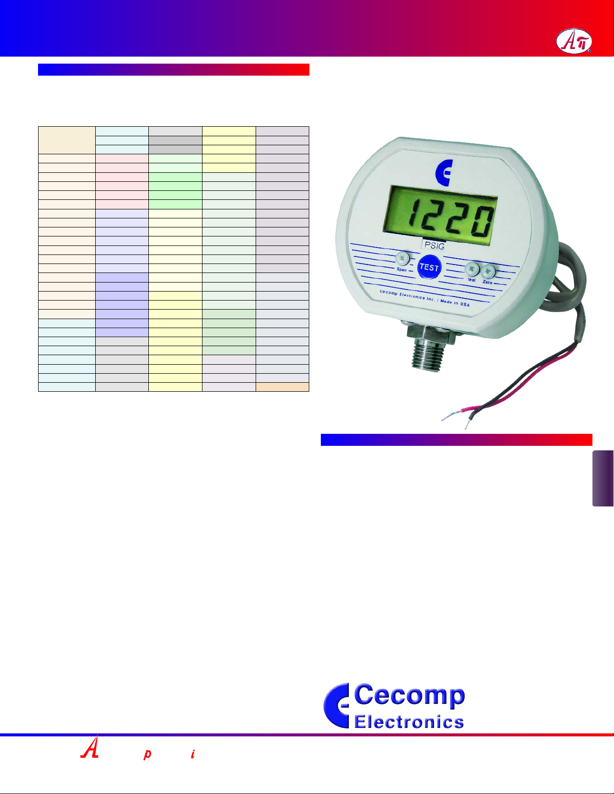
DPG1000DR Series Instructions
© 01-08
Cecomp maintains a constant effort to upgrade and improve its products. Specifications
are subject to change without notice. Consult factory for your specific requirements.
INSTALLATION AND PRECAUTIONS
Install or remove the gauge using wrench on hex fitting only. Do not attempt to tighten by
turning housing or any other part of the gauge. Use fittings appropriate for the pressure
range of the gauge. Do not apply vacuum to gauges not designed for vacuum operation.
Due to the hardness of 316 stainless steel, it is recommended that a thread sealant be used
to ensure leak-free operation. NEVER insert objects into the gauge port or blow out with
compressed air. Permanent damage not covered by warranty will result to the sensor.
NEVER connect the gauge wires directly to 115 VAC or permanent damage not covered
by warranty will result!
ELECTRICAL CONNECTION
The DPG1000DR series can be powered by any 9 to 32 VDC or 8 to 24 VAC 50/60 Hz
power source. An inexpensive unregulated low voltage source can be used. The magnitude
of the supply voltage has negligible effect on the gauge calibration as long as it is within the
stated voltage ranges. Do not allow the gauge supply voltage fall below 9 VDC or 8 VAC
RMS. Operation below these values may cause erratic or erroneous readings or output.
Models with 4-20 mA output power the current loop. Use a power source with sufficient volt-
age to operate the current loop.
Connection is made with the 4-conductor cable at the gauge rear. This cable accommo-
dates both the gauge power supply and retransmission output. If using a 9 to 32 VDC
power source, connect the (+) supply to the RED lead and the (–) supply to the BLACK
lead. If using a 8 to 24 VAC 50/60 Hz power source, connect to the RED and BLACK leads.
When using low voltage AC power, there is of course, no polarity consideration.
The (+) retransmission output appears on the WHITE lead, and the (–) retransmission out-
put appears on the GREEN lead. Use of the shield (drain) wire of the retransmission out-
put is optional. It is not generally needed for 4-20 mA current loops unless very long cable
lengths are used in electrically noisy environments.
Power – BLACK
Power + RED
Output – GREEN
Output + WHITE
The output is a continuous analog signal based on the transducer output rather than the
display. This output is filtered to improve noise immunity and has a response time of about
50 milliseconds.
The power supply (–) lead is tied to the retransmission output ground. Therefore, if a DC
supply is used, the power supply (–) lead should be considered common with regard to the
retransmission output (–) connection.
USING THE RETRANSMISSION OUTPUT
NEVER connect retransmission output wires together or to an external power source or
permanent damage not covered by warranty will result.
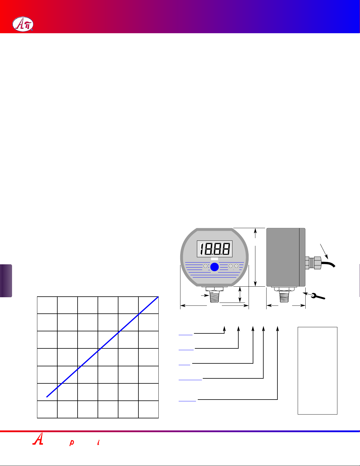
For 4-20 mA output models, be sure to observe the output compliance (voltage drive) capa-
bilities of the gauge. The compliance, and therefore the maximum loop resistance the out-
put can drive, is a function of the supply voltage to the gauge. Consult the graph shown
below for maximum loop resistance vs. gauge supply voltage. Too large a loop resistance
will cause the gauge output to “limit” or saturate before reaching its full 20 mA output.
When using the 0-2 volt retransmission output, do not allow the resistive load on the out-
put to fall below 5K ohms. Avoid large capacitive loads (greater that 1000 pF) such as those
caused by long runs of shielded cable. For long cable runs, use a 4-20 mA output model.
OPERATION
The gauge is powered on whenever a supply voltage is applied. Warm-up time is negligi-
ble. In normal operation, the system pressure is displayed on the LCD and an output sig-
nal will be present. DPG1000DRBL model display backlighting will be on whenever power
is on. The display backlighting will not be apparent under bright lighting conditions.
TEST BUTTON
When the front-panel TEST button is held depressed, the display and retransmission out-
put are switched, independent of the system pressure, to a test level determined by the set-
ting of the Test potentiometer. This test mode will allow setup and testing of the output and
any external device(s) connected to it by switching to this test level whenever desired with-
out having to alter the system pressure.
To set the test output level, see gauge label for location of Test potentiometer. Press and
hold the front-panel TEST button and adjust the Test potentiometer to set the display and
retransmitted output to the desired test level.
CALIBRATION
The gauge is calibrated at the factory using equipment traceable to NIST. There is no need
to calibrate the gauge before putting it in service. Complete calibration instructions can be
downloaded from www.cecomp.com. Gauges may be returned to Cecomp Electronics for
factory certified recalibration. NIST traceability is available.
Span calibration should only be attempted if the user has access to a pressure reference
of known accuracy. The quality of the calibration is only as good as the accuracy of the cal-
ibration equipment and ideally should be at least four times the gauge accuracy.
Absolute reference gauges require vacuum generation and atmospheric pressure meas-
urement equipment for accurate calibration and are more difficult to calibrate in the field.
The calibration system must be able to generate and measure pressure/vacuum over the
full range of the gauge. A vacuum pump able to produce a vacuum of 10 microns (0.01 torr
or 10 millitorr) or lower is required for vacuum and absolute gauges.
1. Low-voltage powered gauges must be connected to 8-24 VAC 50/60 Hz or 9-32 VDC
during the calibration procedure. The supply voltage has negligible effects on the gauge
calibration as long as it is within the stated voltage ranges.
2. Allow the gauge to equalize to normal room temperature before calibration.
3. Access the individual controls to adjust the zero and span of the display.
4. Zero calibration must be done before span calibration.
5. Zero for gauge reference pressure or vacuum gauges: Gauge reference units may
be re-zeroed without affecting the span calibration. The gauge port must be open to the
ambient with no pressure or vacuum applied. Adjust the Zero potentiometer for a display
indication of zero with the minus (–) sign occasionally flashing.
Zero for absolute reference gauges: Apply full vacuum to the gauge. Adjust the Zero
potentiometer for a display indication of zero with the minus (–) sign occasionally flashing.
6. Span for gauge reference pressure gauges and absolute reference gauges: Apply
full-scale pressure and adjust the Span potentiometer for a display indication equal to
full-scale pressure.
Span for gauge reference vacuum gauges: Apply full vacuum to the gauge. Adjust the
Span potentiometer for a display indication equal to full-scale vacuum.
7. Verify pressure indications at 0%, 25%, 50%, 75%, and 100% of full scale and repeat
calibration as needed to achieve best accuracy over desired operating range.
Calibration of the retransmission output coordinates the retransmission output to the dis-
play indication, and normally does not need to be adjusted. It requires a direct physical
measurement of the retransmission output. This calibration procedure can be downloaded
from www.cecomp.com.
DIMENSIONS AND WIRING EXAMPLE
1/4" NPT
Cecomp Electronics Inc./Made in USA
2.88"
3.38"
0.75" 0.75"
1.65"
Turn at
hex
fitting
only!
PSIG
Max Loop Resistance (Ohms)
8121620242832
Supply Voltage (DC or AC RMS)
Voltage Compliance for
4-20 mA Current Retransmission Output
DC Backlit &
non-Backlit
Gauge power supply
9-32 VDC
or
8-24 VAC 50/60 Hz (–)BLACK
(+)RED
(+)WHITE
(–)GREEN
Remote Device Optional
shield
connection
3 ft long, 4-con-
ductor 22 AWG
cable
Span Zero
Test
TEST
1400
1200
1000
800
600
400
200
0
AC 3000 & 5000 psi
DC 3000 & 5000 psi
Zero, Test, Span pots for
3000 & 5000
psi ranges
AC Backlit
AC
BSOLUTE ROCESS NSTRUMENTS, Inc.
1220 American Way Libertyville, IL 60048
Phone: 800-942-0315 Fax: 800-949-7502
For latest product information or to contact
your local representative visit api-usa.com
Pressure