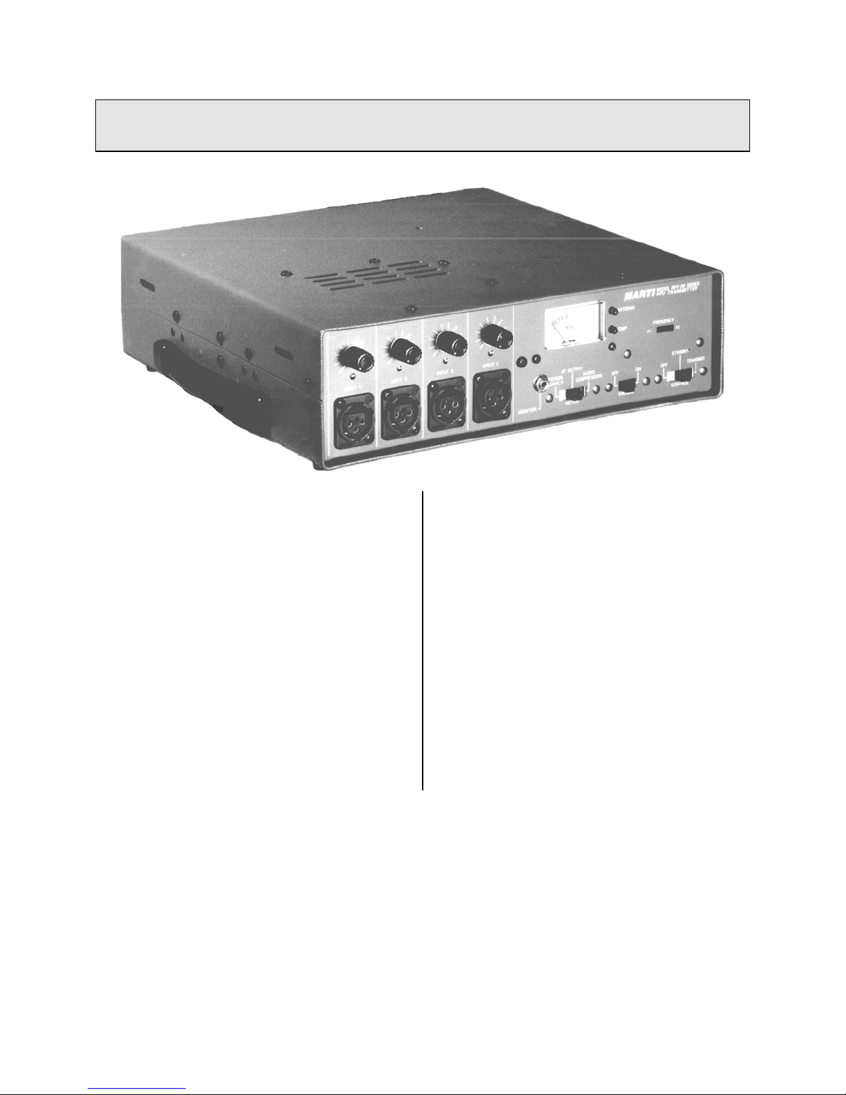
Marti RPT-30 User manual

WARNING
THIS EQUIPMENT MUST BE OPERATED WITH A 3-PRONG
GROUNDED OUTLET RECEPTACLE. FAILURE TO USE A
PROPERLY GROUNDED OUTLET MAY RESULT IN IMPRO-
PER OPERATION OR SAFETY HAZARD!
LIMITED WARRANTY
The Seller warrants that, at the time of shipment, the
products manufactured by the Seller are free from
defects in material and workmanship. The Seller's
obligation under this warranty is limited to replace-
ment or repair of such products which are returned to
Marti at its factory, transportation prepaid and
properly insured, provided:
a. Notice of the claimed defect is given to Marti
within one (1) year [two (2) years for STL systems]
from date of original shipment and goods are re-
turned in accordance with Marti instructions.
b. Equipment, accessories, tubes and batteries not
manufactured by Marti are subject to only such ad-
justments as Marti may obtain from the supplier
thereof.
c. This warranty does not apply to equipment
which has been altered, improperly handled, or dam-
aged in any way.
The Seller is in no event liable for consequential
damages, installation cost or other costs of any nature
as a result of the use of the products manufactured or
supplied by the Seller, whether used in accordance
with instructions or not.
This warranty is in lieu of all others, either expressed
or implied. No representative is authorized to assume
for the Seller any other liability in connection with
Seller's products.
MAILING & SHIPPING ADDRESS:
MARTI Electronics, Inc.
P.O. Box 661 1501 N. Main St.
Cleburne, Texas 76031-0661
The United States of America
COPYRIGHT NOTICE
©1993 All Rights Reserved
Marti Electronics, Inc.
4th printing, December 1993
No part of this manual may be reproduced, transmit-
ted, transcribed, stored in a retrieval system , or
translated into any language, natural or computer, in
any form or by any means, without the prior written
permission of Marti Electronics, Inc.
Artwork depicting circuitry in this manual is pro-
tected by copyright laws.
Information in this manual is subject to change
without notice and does not represent a commitment
on the part of Marti Electronics, Inc.
Marti Electronics may make improvements and/or
changes in this manual or in the product described
herein at any time.
This product could include technical inaccuracies or
typographical errors.
PHONE NUMBERS:
Sales & Service (817) 645-9163
FAX (817) 641-3869

Table of Contents
Introduction .................................................................................................................. 1
Specifications ................................................................................................................ 2
Unpacking and Inspection ............................................................................................. 3
Installation .................................................................................................................... 4
Electrical Connections ................................................................................................... 4
Antennas .......................................................................................................................
Operation ......................................................................................................................
Step by Step Operating Procedure .................................................................................
Theory of Operation ......................................................................................................
Tools and Test Equipment Required ..............................................................................
Block Diagram, Drawing No. 702-073 ..........................................................................
Location of Adjustments, Drawing No. 702-076 ...........................................................
Factory Test Report ......................................................................................................
Tune-Up Procedure and Adjustment ..............................................................................
Function of RPT-30 Semi-Conductors ...........................................................................
Main Frame Schematic, 702-074 ......................................................
Parts List, 702-074 .......................................................
Pre-Amp/Mixer Schematic, 800-251 ......................................................
Board Parts List, 800-251 .......................................................
Audio Board Schematic, 800-166 ......................................................
Parts List, 800-166 .......................................................
Modulator Schematic, 800-160 ......................................................
Board Parts List, 800-160 .......................................................
Multiplier Schematic, 800-163 ......................................................
Board Parts List, 800-264 .......................................................
RF Power Amp Schematic, 800-170 ......................................................
Board Parts List, 800-170 .......................................................
Output Filter Schematic, 800-250 ......................................................
Board Parts List, 800-250 .......................................................
Power Supply Schematic, 800-249 ......................................................
Board Parts List, 800-249 .......................................................
Meter Board Schematic, 800-252 ......................................................
Board Parts List, 800-252 .......................................................

This page intentionally left blank

Introduction
The Marti Model RPT-30 Transmitters are
designed to operate in the Remote Pick-Up
Broadcast Service as defined in Part 74, Subpart
D, of the FCC Rules and Regulations. Refer to
“Specifications” for a listing of the available
bandwidths. These transmitters, when used with
the recommended companion receiver, provide a
remote broadcast link having audio quality not
approached by conventional voice communica-
tion radio equipment. The RPT-30 transmitter
operates from both 115 volt, 50 - 60 Hz. AC
commercial power and 11 to 14 volt battery
(NEGATIVE GROUND) supply in fixed, port-
able, or mobile, service. Four audio input chan-
nels are provided with individual mixing gain
controls. A meter and selector switch are pro-
vided for monitoring audio compression, RF
output, and power supply voltage. The solid-
state audio processing technique pioneered and
proven by Marti Electronics in thousands of re-
mote pick-up broadcast transmitters over the
past 25 years has been applied to this model, re-
sulting in the highest audio quality possible,
consistent with transmission bandwidth and
other factors.
The RPT-30 has been designed to operate
with other Marti equipment to form large com-
munications systems capable of covering large
areas with broadcast-quality audio, while pro-
viding continuous-duty operation. The RPT-30
finds applications in mobile repeaters, fixed
automatic repeaters, base stations, and TSL
(transmitter-to-studio data links).
RPT-30 Features:
•Continuous-duty output - 45 watts at 150 MHz. - 30 watts at 450 MHz.
•Four balanced microphone mixing inputs, one switchable to balanced line level.
•Dual-Frequency capability.
•Sub-Audible Encoder.
•Internal FM Compressor-Limiter.
•Internal Noise Reduction System (2:1 Audio Compander - optional)
•Flashing LEDs indicate antenna VSWR problems and over-temperature conditions
•Illuminated VU Meter.

Model RPT-30
Remote Pick-Up Broadcast Transmitter
Specifications
Frequency Range and
Maximum Power Output:
140 - 180 MHz. - 45 watts
200 - 260 MHz. - 40 watts
280 - 340 MHz. - 35 watts
400 - 480 MHz. - 30 watts
RF Connector: SO-239
Operating Temp. Range: -10 Cºto +45 Cº
Modulation (Specify): 10KOF3E
25KOF3E
50KOF3E
FCC Frequency Group P
FCC Frequency Group K, L, N2
FCC Frequency Group N1, R
Channels (Frequencies): Two frequencies selected by switch. Frequency separation
1.1% maximum.
Frequency Stability: Mobile: .0005%
Base: .00025% (above 400 MHz.)
Spurious Emissions: Meets FCC requirements.
Audio inputs: Four balanced microphone (150 ohms) inputs (XLR-3) with
mixing controls. One input switchable to balanced line level
at microphone #4 input and D connector on rear panel.
Modulation Control: Broadcast-quality compressor/limiter built in.
Encoding: Subaudible 27 Hz. tone encoder built in.
Metering/Indicators: Illuminated meter indicates audio compression, relative RF
output, relative supply voltage. Flashing LEDs indicate
“Antenna” (VSWR too high) and “Temp.” (over-tempera-
ture indicator).
Controls: (4) INPUT LEVEL, METER switch, ENCODE switch,
FREQUENCY switch, MONITOR jack.
Power Requirements: 120/220/240 VAC (voltage to be specified on original or-
der), 50/60 Hz
DC operation on 11 - 13.5 volt negative ground.
AC Fuse Rating: For 120 v. use 2 1/2 Amp fuse
Accessory Connector: 9-pin D connector for DC power, remote control, encode,
line level input.

Weight: Net 12.4 pounds. Domestic packed 16 pounds.
Net 5.62 kilograms. Export packed 7.62 kilograms.
Dimensions: 11.5 in. wide x 3.5 in. high x 13.3 in. deep.
(29.21 cm. wide x 8.89 cm. high x 33.78 cm. deep.)
Options available: Second crystal for dual-frequency operation, rack mounting
brackets, mobile mounting brackets, antenna switching
relay, audio companding, etc. For a complete listing see last
page of this manual.
Type Acceptance
Numbers (FCC Part 74):
FCC ID: BEN9EZRPT30-150
FCC ID: BEN9EZRPT30-450
DOC (Canada)
Numbers:

UNPACKING & INSPECTING
This equipment was factory tested,
inspected, packed, and delivered to
the carrier with utmost care. Do not
accept shipment from carrier which
shows damage or shortage until the
carrier's agent endorses a statement
of the irregularity on the face of the
carrier's receipt. Without
documentary evidence, a claim
cannot be filed.
Unpack equipment immediately
upon receipt and thoroughly inspect
for concealed damage. If damage is
discovered, stop further unpacking
and request immediate inspection
by local agent of carrier. A written
report of the agent's findings, with
his signature is necessary to support
claim. Check your shipment against
the shipping papers for possible
shortage. Do not discard any packing
material until all items are accounted
for. Small items are often thrown
away with packing material. Packing
material should be retained until
equipment testing is completed. Any
equipment returned to the factory
should be packed in original cartons,
insured, and pre-paid.

Installation
Install rack-mounted equipment in a well-ventilated,
well-grounded, and shielded rack cabinet. Do not locate
solid-state equipment in a rack above tube-type
equipment which produces high temperatures.
Problems can also be avoided by locating this unit
away from other equipment which has transformers
that produce strong magnetic fields. These fields can
induce hum and noise into the Marti equipment thus
reducing performance. Strong radio-frequency (RF)
fields should be avoided where possible. Extensive
shielding and filtering have been incorporated into this
equipment to permit operation in moderate RF environ-
ments. All equipment racks, cabinets, etc., should be
bonded together by wide copper grounding strap to
ensure that all system elements are at RF ground
potential.
STATIONARY REMOTE BROADCAST
INSTALLATION
The basic stationary remote installation consists of the
RPT-30 transmitter, a 115 VAC power source, micro-
phones and other audio program sources, and a portable
antenna. Remotes using portable antennas inside build-
ings have very limited range (typically less than one
mile). If greater range is needed, consider locating the
transmitting antenna outside the building at a height
necessary to provide a line-of-sight path to the receiving
antenna. This may not be practical if a great length of
coaxial cable is required. Many broadcasters are using the
Marti mobile relay system to do remotes from inside
buildings. This system consists of the originating
transmitter with its antenna inside the building which
transmits to a “mobile relay” parked outside the building.
The mobile relay consists of a Marti Model AR-10 re-
ceiver and Marti RPT series transmitter with mobile
antennas installed in a vehicle. The AR-10 receiver picks
up the encoded signal originating from the RPT series
transmitter located inside the building, automatically turns
on the relay transmitter (on a different frequency), which
re-transmits the program to the distant receiving antenna
at the radio station studio or transmitter site. (Mobile
relay equipment packages are available from Marti.)
STATIONARY REMOTE INSTALLATION
PROCEDURE
1. The transmitter is normally located near the announcer
or engineer to permit access to gain controls, microphone
inputs, the monitor jack, and metering.
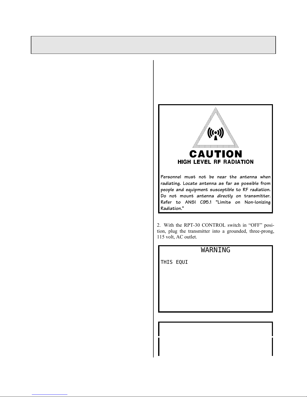
Personnel must not be near the antenna when
radiating. Locate antenna as far as possible from
people and equipment susceptible to RF radiation.
Do not mount antenna directly on transmitter.
Refer to ANSI C95.1 “Limits on Non-Ionizing
Radiation.”
2. With the RPT-30 CONTROL switch in “OFF” posi-
tion, plug the transmitter into a grounded, three-prong,
115 volt, AC outlet.
WARNING
THIS EQUIPMENT MUST BE OPERATED WITH
A 3-PRONG, GROUNDED, 115 VOLT, AC
OUTLET RECEPTACLE!
FAILURE TO USE A PROPERLY GROUNDED
OUTLET COULD RESULT IN A SAFETY HAZ-
ARD OR FAULTY EQUIPMENT PERFORMANCE.
IF AN EXTENSION CORD IS USED, IT
MUST BE THE THREE-WIRE GROUNDING
TYPE TO INSURE SAFETY.
DO NOT CUT OFF THE GROUND PIN OF A
3-PRONG PLUG!
Excessively long extension cords
should be avoided since the voltage
drop can degrade equipment

performance. Do not allow the RPT-30
to get wet. Do not operate where
personnel touching the transmitter
(or its microphone, antenna, or
other connected equipment) are
standing on wet ground or concrete.
3. For locations where AC power is not available, the
RPT-30 can be powered from a fully charged automobile
battery. The RPT-30 draws five (5) amps at 12.6 volts
DC. Use D.C. Power Cable, Fuse and Plug, No. 586-074.
OBSERVE POLARITY: Red wire is (+) Positive and
Black is (-) Negative.
4. Connect a portable antenna such as the Marti
PAV/150, PAV-450, or YC-450 to the ANTENNA con-
nector on the back of the transmitter.
MOBILE INSTALLATION
The RPT-30 transmitter can be installed in the vehicle
where the controls (“OFF” - “STANDBY” - “TRANS-
MIT”) can be operated directly, or the transmitter can be
located elsewhere (in the trunk of a car or rear of a van)
and controlled remotely. The choice depends upon the
type of vehicle and the type of operation anticipated. The
antenna(s) are usually mounted on top of the vehicle to
provide maximum height.
Transmitter Mounting
1. Locate transmitter where vent holes on top and rear of
unit are not obstructed. Leave enough space for the mic.
plug on the front panel and the accessory plug on rear of
unit.
2. Hook the four mounting fasteners (in retracted posi-
tion in the four slots on the sides of the transmitter. See
Fig. 1. (Fasteners are in Mobile Mounting Kit, 700-251)
3. Mark the location of the two mounting holes in each
fastener bracket. Drill 7/64” diameter holes into the
mounting surface at the marked places for #6 x 1/2” sheet
metal screws.
4. Attach the mounting fasteners with the sheet metal
screws provided. Secure the transmitter with the fasten-
ers.
Receiver Mounting
For mobile repeat using the Marti AR-10 Mobile Re-
peat Receiver, mount the receiver near the transmitter
using the three fasteners supplied in Mobile Mounting
Kit, 700-251.
Electrical Connections
WARNING: This equipment is designed for NEGA-
TIVE GROUND, 12 volt vehicles only. Reverse polar-
ity may destroy all transistors in the RPT-30!

Mobile Remote Control
Remote control of the RPT-30 transmitter requires a
switch to control primary +12 volt DC power and a sec-
ond switch to control the transmit function. The primary
+12 volt control requirement can be met by tapping the
“Accessory” circuit of the vehicle which is controlled by
the ignition switch. The “transmit” function can be per-
formed by installing a switch on the vehicle or by the
push-to-talk switch on a microphone such as the Marti
MCD-70B.
FIG. 2. shows the electrical circuit of a mobile instal-
lation.
CAUTION: TOTAL CONTROL CIRCUIT RESISTANCE MUST
NOT EXCEED 0.3 OHMS!
Control circuits having more than 0.3 ohms resistance
should employ a relay with low resistance contacts lo-
cated near the transmitter.
Mobile Repeat
Mobile repeat operation is covered under STATION-
ARY REMOTE BROADCAST INSTALLATION. Electrical
connection is through Mobile Repeat Cable No. 585-037-
2. This cable is connected between the RPT-30
transmitter and AR-10 receiver. Power is obtained by
connecting the fused RED wire to the vehicle
“Accessory” +12 volt circuit controlled by the vehicle
ignition switch. The electrical diagram of this cable is
shown in FIG. 3.
Mobile Antenna Installation
One or more mobile antennas are required depending
upon the various receive and transmit frequencies and
whether antenna duplexing is used. Antennas are speci-
fied in the various system packages listed in the Marti
literature. The installer should follow the instructions
supplied with the mobile antennas.

FIXED BASE STATION, TSL, & RE-
PEATER INSTALLATION
1. Install transmitter in standard rack by using Rack
Mounting Kit No. 700-253 available from Marti. CAU-
TION: Allow one panel space above and below transmit-
ter for inlet air-flow to internal fan.
2. Connect transmitting antenna to ANTENNA connec-
tor on RPT-30 rear panel.
3. If a receiver is to share the antenna with the transmit-
ter (as in a two-way base station), the transmitter must be
equipped with optional Antenna Relay No. 570-038
available from Marti. After relay is installed, connect
RECEIVER jack on RPT-30 rear panel to receiver an-
tenna connector using 20-inch Coaxial Cable No. 585-
026. Receiver muting during transmitting is accomplished
using Mute Cable No. 585-038-2. This cable plugs into
the ACCESSORY connectors on each unit.
4. Plug transmitter into a 3-prong, grounded 115 volt,
AC outlet. WARNING: Failure to use a properly
grounded outlet could result in a safety hazard or faulty
equipment performance.
5. For fixed automatic repeater operation, connect Cable
No. 585-037-1 (FIG. 4.) between accessory connectors of
the receiver and RPT-30 transmitter. Connect receiving
antenna to receiver J6 and transmit antenna to RPT-30
ANTENNA connector.

ANTENNAS
BASE STATION ANTENNA IN-
STALLATION CHECKLIST
The following suggestions are offered to help
those responsible for antenna installations avoid costly
errors in assembly and adjustment. Marti Electron-
ics, Inc. assumes no responsibility for the installation
and performance of antenna systems associated with
its equipment. The following suggestions are not
intended to be a complete step-by-step procedure,
simply a listing of some of the most frequently re-
ported errors in antenna system installation.
Antenna Assembly
Follow the manufacturer's instructions carefully. If
no instructions were included with the antenna, call or
write the antenna manufacturer for instructions. Anten-
nas which have phasing or stacking cables must be as-
sembled carefully to avoid phase reversal or signal can-
cellation.
Transmission Line Connector Assembly
Do not use RG-58 U or RG-8 U cable for STL
station antennas! They have too much loss at VHF and
UHF frequencies. Follow the instructions furnished by
the manufacturer when cutting coaxial cable. Inspect the
cable ends for small metal fragments which can short-
circuit the line inside the connector assembly. Check the
line for a short-circuit condition after each connector is
installed by using an ohmmeter. Pressurized line should
be checked for several days under pressure before instal-
lation on a tower to ensure that there are no leaks in the
line or fittings
Moisture Proofing Coax Connectors and
Fittings
Extreme care must be exercised with coaxial cable
before and after connectors have been installed to ensure
that moisture does not enter the line. Foam dielectric line
can take on moisture absorption which is difficult to
detect and remedy. Therefore, keep the line dry while in
storage with ends tightly capped. Coaxial splices, connec-
tors, and fittings, to be located outside should be made
mechanically tight, then coated with a weather-proofing
material over at least two layers of vinyl plastic electrical
tape. Moisture problems in antenna systems are usually
traced back to connectors which have NOT been properly
taped. The Marti K-1 Grounding and Weatherproofing
Kit is recommended for use in each new antenna
installation.
Location and Grounding of Coaxial Ca-
ble
Keep the RPU receiver coaxial cable as far from the
broadcast transmitter and its coaxial cable as possible.
DO NOT STRAP RECEIVER CABLE TO THE MAIN
ANTENNA CABLE AT ANY POINT. PLACE THE
RECEIVER ANTENNA COAXIAL CABLE ON THE
OPPOSITE SIDE OF THE TOWER FROM THE
MAIN ANTENNA CABLE. Maintain maximum separa-
tion between these cables at all points, including the dis-
tance from tower base to transmitter building as well as
inside the building.
System Grounding
It is essential that the RPU antenna system be
properly grounded for safety and proper operation.
Antenna Installation and Adjustment
The polarization of the transmit and receive antennas
of the RPU system must be the same! This means that if
the transmitting antenna is vertical, the receiving antenna
must also be vertical. Each antenna should be attached to
the tower using the proper side mount or top mount
hardware. If an RF wattmeter is available, each antenna
and transmission line can be checked for VSWR when the
transmitter is supplying power to it. The VSWR should
be less than 1.5 to 1 (1.5:1). IF THE ANTENNA
SYSTEM FAILS TO GIVE THE PREDICTED
SIGNAL STRENGTH LEVEL, THE FOLLOWING
ITEMS SHOULD BE CHECKED:
1. Check for correct assembly of antenna.
2. Check that antennas have same polarity.
3. Check VSWR of both transmit and receive antennas.
VSWR should be less that 1.5:1.
4. Check for obstructions in the path such as trees and
man-made structures. The base antenna must be high
enough to provide a line-of-sight path to the remote
transmitting antenna.
CAUTION & WARNING
YOU CAN BE KILLED IF AN ANTENNA COMES IN
CONTACT WITH ELECTRIC POWER LINES OR
EXPOSED ELECTRICAL WIRING. FOR YOUR
SAFETY USE EXTREME CAUTION WHEN IN-

STALLING ANTENNAS. KEEP AWAY FROM
POWER LINES.

Operation
CONTROL & CONNECTOR
FUNCTIONS
FREQUENCY Switch
This switch selects one of two possible operating
frequencies. If you have only one frequency, make sure
the switch is not accidentally switched to the unused
position, since the transmitter will NOT operate in this
condition.
MIC Input Connectors
These balanced inputs are for a 150 ohm dynamic
microphone such as the Marti MCD-70C or MCD-70D
with standard XLR-3 or A3M connector. Microphone
connections are given in INSTALLATION.
Input 4 can operate at MIC LEVEL or HIGH LEVEL
by means of a SELECTOR SWITCH inside the transmit-
ter just behind the Input 4 pot. The unit is factory selected
for “HI” (HIGH) LEVEL balanced input for use with tape
machines, etc. To convert Input 4 to MIC (microphone)
LEVEL, remove top cover and move switch to “MIC”.
ACCESSORY Input Connector
When Input 4 is switched to “HI” level, audio can be
fed into pins 2 and 3 of the ACCESSORY connector on
the rear of the transmitter. Input level should be between
0.2 volts to 2.0 volts rms. The output impedance of the
device connected to Input 4 should be 8 - 600 ohms. For
unbalanced operation ground pin 2 to pin 5 and connect
audio to pin 3. Use standard 9-pin “subminiature D” fe-
male connector with cover. “TRANSMIT” control can be
accomplished remotely by a low resistance switch circuit
connected to pins 7 and 9. CAUTION: TOTAL CON-
TROL CIRCUIT RESISTANCE MUST NOT EX-
CEED 0.3 OHMS!
GAIN Controls
The GAIN potentiometer located above each input
connector provides an independent level adjustment for
that input. Each GAIN potentiometer is adjusted as fol-
lows:
1. Connect input source at normal audio level.
2. Turn GAIN potentiometer to maximum counter-
clockwise (“OFF”) position.
3. Place CONTROL switch in “STANDBY” position
and allow METER pointer to reach 0 VU. Slowly in-
crease gain (clockwise) until METER begins deflecting to
the left on audio peaks. Maximum deflection should be -3
to -5 VU on the METER scale. This indicates 100%
modulation of the transmitter. Excessive gain settings
cause high compression values which result in annoying
increase in background noise. A 600 ohm headset may be
plugged into the MONITOR jack to aid in arriving at the
proper gain adjustment. In high noise environments,
close-talk the microphone and reduce MIC gain until a
maximum of -2 VU gain-reduction is indicated.
4. Once the proper gain level is determined, it will not be
necessary to change it for that particular microphone or
tape player. The broadcast quality compressor/limited
built into the unit will maintain modulation at the maxi-
mum level while preventing overmodulation.
CONTROL Switch
When the transmitter is not in use the CONTROL
switch should be in the “OFF” position. The switch
should be placed in “STANDBY” position at least 2
minutes before transmission is anticipated. This activates
all audio circuits, MONITOR jack and METER. Current
drain is minimal in “STANDBY” position. The CON-
TROL switch is placed in “TRANSMIT” position when
transmission is desired. The CONTROL switch should be
returned to “STANDBY” or “OFF” position as soon as a
transmission is completed.
ENCODE Switch
The internal subaudible encoder can be switched
“ON” or “OFF” by the front panel switch. Encoding is
used to activate a repeater station, tape recorder, etc.
MONITOR Jack
The MONITOR jack is active in “STANDBY” and
“TRANSMIT” positions of the CONTROL switch. A
high-quality headset having 300 ohms or higher imped-
ance can be plugged into the MONITOR jack to make
adjustments or to monitor the quality of the audio being
transmitted. A miniature, single circuit, 1/8 inch, phone
plug should be used with the MONITOR jack.

METER
The VU METER serves the function of indicating the
relative power supply voltage, relative RF power output,
and the amount of audio compression. The METER indi-
cates RF output only when the CONTROL switch is in
the “TRANSMIT” position.
ANTENNA Connector
Connection of various antenna systems is covered un-
der INSTALLATION and ANTENNAS. It is only necessary
for the operator or announcer to see that the ANTENNA
connector is tight and that the antenna is clear of objects
which may affect its radiation efficiency. CAUTION:
THE ANTENNA MUST BE CONNECTED BEFORE
SWITCHING TO “TRANSMIT”.
RECVR Connector
If the RPT-30 is equipped with optional antenna relay,
the transmit antenna can be used for receiving by
connecting a coaxial cable (No. 585-026) between the
RECV jack on the RPT-30 and ANTENNA connector of
the receiver (MARTI AR-10). To silence the receiver
while transmitting, Mute Cable No. 585-038-2 is plugged
into the ACCESSORY connector on each unit.
ANTENNA (WARNING LIGHT)
The red LED light marked “ANTENNA” which is to
the right of the METER on the RPT-30 front panel,
flashes to indicate a problem with the antenna when
transmitting. The ANTENNA (WARNING LIGHT)
flashes if the CONTROL switch is switched to
“TRANSMIT” without an antenna connected. It can also
indicate a defective antenna, coaxial cable, or connector;
or improper location of a portable antenna. Prolonged
operation under these conditions can damage the
transmitter.
TEMP (WARNING LIGHT)
Flashing of the TEMP (WARNING LIGHT) indicates
excessive operating temperature within the transmitter.
This can be caused by obstructed vent holes in the top or
rear of the unit, inoperative cooling fan, or antenna prob-
lems. Do not operate RPT-30 until the cause of overheat-
ing is corrected!
STEP BY STEP RPT-30 OPERAT-
ING PROCEDURE
1. Position CONTROL switch to “OFF”, then plug RPT-
30 into a 115 volt, AC, grounded, 3-prong receptacle.
WARNING
THIS EQUIPMENT MUST BE OPERATED WITH
A 3-PRONG, GROUNDED, 115 VOLT, AC
OUTLET RECEPTACLE!
FAILURE TO USE A PROPERLY GROUNDED
OUTLET COULD RESULT IN A SAFETY HAZ-
ARD OR FAULTY EQUIPMENT PERFORMANCE.
IF AN EXTENSION CORD IS USED, IT
MUST BE THE THREE-WIRE GROUNDING
TYPE TO INSURE SAFETY.
DO NOT CUT OFF THE GROUND PIN OF A 3
PRONG PLUG!!
2. Connect antenna to the ANTENNA connector on the
RPT-30 rear panel.
3. Place CONTROL switch in “STANDBY” position.
(Allow for a 2 minute warm-up!)
4. Plug in microphones (Inputs 1 - 3) or tape player
(Input 4 internally switched to “HI” position. See MIC
Input Connections, above.) and check operation by ob-
serving compression on METER and by headset plugged
into MONITOR jack. Set GAIN controls for no more
than -3 VU audio compression on the METER.
5. To transmit, move CONTROL switch to
“TRANSMIT” position. The METER should read 0 VU
±3 VU with METER switch in “RF OUTPUT” position.
6. If the ANTENNA (WARNING LIGHT) flashes in
“TRANSMIT” operation, switch transmitter “OFF” im-
mediately and check antenna, connectors, and coaxial
cable. Placing antenna too near a wall or other object can
cause ANTENNA (WARNING LIGHT) to flash.
7. Flashing of the TEMP (WARNING LIGHT) indi-
cates: (a) Obstructed vent holes in top or rear of unit. (b)
Fan not operating. (c) Improper tuning, antenna load, or
other problems causing excessive heating. Do not operate
RPT-30 until cause of overheating is corrected!!!

THEORY OF OPERATION
Refer to Block Diagram Drawing No. 702-073 and appropriate Schematic Diagrams.
PRE-AMP/MIXER BOARD, 800-251
Each of the four microphone inputs is fed to a low-
noise differential op-amp (half of an NE-5532). Critical
resistors in the input circuits are low-noise, precision,
temperature stable types to obtain maximum performance
from the pre-amps. Monolithic chip capacitors are used to
filter RF voltages that may be present at the microphone
inputs. The four op-amp outputs are fed to gain pots then
resistively mixed and routed to the COMPRESSOR
BOARD.
COMPRESSOR BOARD, 800-166
Several functions are performed on this board.
Integrated Circuit IC-1 serves as a (a) pre-amp [not used
on the RPT-30, (b) pre-emphasis amplifier, (c) voltage-
controlled attenuator, (d) regulator/ripple rejection. Pre-
emphasized audio out of IC-1B is also fed to D2 - D3
which form an adjustable series peak-limiting circuit.
This circuit is adjusted to limit only audio peaks which
get past the compressor. The limiter circuit feeds a low-
pass filter (L1, C23, R46) which reduces the audio
bandwidth to that specified for the operating channel of
the transmitter. To this is mixed the output of the tone
encoder, IC-2A, which is a low-distortion Wien bridge
oscillator. This composite signal is then fed to the FM
Modulator. This audio signal is also fed to IC-2B which
amplifies it to a level suitable for a 600 ohm headphone
monitor. IC-2C is a DC amplifier the input of which is
connected to the AGC (automatic gain control) circuit and
the output of which drives the audio compression meter.
FM MODULATOR, 800-160
The modulator consists of a voltage-controlled crystal
oscillator, Q1, precision voltage regulator, IC-1, and oven
heater control, Q2. Precise frequency control is obtained
by thermally coupling components Y-1, Q1, Q2, and IC-1
to the temperature-regulated Frequency Control Module
No. 800-160-1.
MULTIPLIER BOARD, 800-163
The modulator RF output is frequency-multiplied in
the multiplier board to obtain the various operating
frequencies listed on the RPT-30 specification sheet.
The multiplication factor for various frequency bands
is as follows:
140 - 180 MHz 12 X
200 - 260 MHz 16 X
280 - 340 MHz 24 X
400 - 480 MHz 24 X
The power level at the input to the multiplier is
approximately 5 mw. and the output level is 0.9 to 1.5
watts.
RF POWER AMPLIFIER, 800-170
RF output of the MULTIPLIER BOARD is connected
to the input of the power amplifier board at a 50 ohm
impedance. Transformation of the 50 ohm input to the
base impedance of Q1 is accomplished by C1, C2, and
L1, L2, and L3. L4 and L5 provide a path for Q1 base
current and the L5 - R1 parallel circuit reduces low
frequency gain and instability. The RF output power of
Q1 is approximately 10 watts and is fed to the base of Q2
by the L-C impedance matching network shown on the
schematic. L13 and R2 reduce low-frequency gain and
instability. RF power at the collector of Q2 is matched to
50 ohms by the L-C network shown. The collector supply
to Q1 and Q2 is decoupled by L8 and C5 - C10.
OUTPUT LOW-PASS FILTER,
DIRECTIONAL COUPLER, 800-250
RF output from the RF POWER AMPLIFIER passes
through a four-section low-pass filter and directional-
coupler before reaching the output connector. The
directional-coupler is of stripline construction. The
forward power sample of this coupler is supplied to the
“RF OUTPUT” METER, and the reflected power sample
is fed to comparator IC-1A on the METER BOARD and
flashes the ANTENNA (WARNING LIGHT) LED to
indicate high VSWR. R5 and R6 calibrate the forward
and reflected power samples. Circuitry for an optional
antenna relay is provided on the board. When installed,
this relay switches the antenna from RECVR (receiver)
jack to transmitter output for two-way operation.
POWER SUPPLY, 800-249
Board 800-249 contains filter capacitors C1 and C2,
voltage adjust pot R1, and reverse polarity protection
diodes D1, D2, and D3. The unregulated output voltage
of this supply is 17 - 20 volts, and is supplied from bridge
rectifier D1. Series regulator IC-1 is located on the large

heat sink at the rear of the transmitter, and supplies 13.5
volts DC at 5 amps.
INPUT/OUTPUT FILTERS, 800-253
All input/output circuits connected to ACCESSORY
connector, as well as the AC line input, have radio-
frequency filters. In addition to the L and C filter
components, a reverse polarity protector diode D2 is
located on the 800-253 board.
METER BOARD, 800-252
The METER, meter illumination lamp, ANTENNA
(WARNING LIGHT) and TEMP (WARNING LIGHT)
LEDs, with their comparator drivers, IC-1A, IC-1B are
located on the METER BOARD.

Test Equipment
Distortion Analyzer Krohn-Hite Model 6801
Oscillator Krohn-Hite Model 4500
Attenuator Set Hewlett-Packard Model 3500
Frequency Counter Hewlett-Packard Model 5383A
(option 001)
Digital Multimeter Beckman Model 3030
Analog Multimeter Triplett Model 630
RF Attenuator adjustable 0-110 dB
RF Signal Generator Marconi Model 2022C
Spectrum Analyzer Hewlett-Packard Model 8558B
Wattmeter (50 ohms impedance) Bird Model 43
5 or 50 watt element 100-250 MHz or 400-1000 MHz, Bird
Automatic Modulation Meter Wavetek Model 4101
50 watt RF Load Microwave Associates Model 44003
Stereo Monitor Belar Model FMS-2
Stereo Generator Aphex Model AX400
Oscilloscope Tektronix Model 2215
Tools for Alignment
Tuning Tool GC 9300
Tuning Tool GC 9440
Tuning Tool Spectrol 8T000
Tuning Tool Sprague-Goodman
Screwdriver Xcelite R184, 1/8” x 4”

This page intentionally left blank

RPT-30 Transmitter
FACTORY TEST DATA
Customer: _______________________________________________________________________
Address: ________________________________________________________________________
Serial No.:__________ Frequency #1 (F1):___________ Frequency #2 (F2):___________
140 - 200 MHz 200 - 480 MHz
TP1 0.35 - 0.70 TP1 0.25 - 0.50
TP2 0.40 - 0.80 TP2 0.20 - 0.60
TP3 NOT USED TP3 0.60 - 1.20
TP4 0.25 - 0.50 TP4 0.45 - 0.90
TP5 0.30 - 0.60 TP5 0.80 - 1.60
q8 volt regulator (7.45 - 7.65)
qAudio Compressor Meter set at 0 VU
qLimiter Set
qEncode frequency set at 27 Hz.
qEncode frequency set at 1 KHz. deviation
qSet power on 120 volt AC operation at __________watts
qDC voltage on 120 volt AC operation (13.5 volts DC)
qResponse within specifications
qDistortion within specifications
qSignal to noise within specifications
qMetering satisfactory
Test Equipment ______________________________________
Frequency Counter, HP Model 5383A DATE
Deviation Monitor, Wavetek Model 4101
______________________________________
SIGNATURE
Table of contents
Other Marti Transmitter manuals
Popular Transmitter manuals by other brands

Nice
Nice FLOX1R Installation instructions manual

Suntor
Suntor ST30NMT user manual

JUMO
JUMO dTRANS T06 Ex operating manual

WAREMA
WAREMA WMS Hand-held transmitter comfort Operating and installation instructions

CyberData
CyberData Wireless IP Pendant Specification sheet

Microsensor
Microsensor MPM4841 Operation manual