PushCorp RPC100-75 User manual

RPC100-
75/125/150
Robotic Paper Changer
User Manual
October, 2020
PUSHCORP, INC.
Dallas, Texas

CAUTION
The Robotic Paper Changer
contains calibrated electronics.
ANDLE WIT CARE DO NOT DROP
DO NOT USE LUBRICATED AIR.
This device requires a dry, non-
lubricated 43.5 to 72.5 psi (3 – 5 bar) air
supply filtered to 5 µm and a 0.3
micron oil mist separator.
Non-compliance with these
requirements will void the
manufacturer’s warranty.
(See Section 4.3)
All fasteners, mounting holes and
pipe threads on this tool are
METRIC.

PUSHCORP, INC.
RPC100-75/125/150 Manual
Table of Contents
1.0 LIMITED WARRANTY...........................................................................................2
2.0 GENERAL OVERVIEW.........................................................................................4
3.0 QUICK START.......................................................................................................5
4.0 INSTALLATION.....................................................................................................6
4.1 Mounting Process Equipment.......................................................................................................... 6
4.2 Pneumatic Connection.................................................................................................................... 8
5.0 OPERATION........................................................................................................10
6.0 ELECTRICAL CONNECTIONS...........................................................................17
7.0 TEC NICAL SPECIFICATIONS.........................................................................18
8.0 PREVENTATIVE MAINTENANCE SC EDULE.................................................19
1

PUSHCORP, INC.
RPC100-75/125/150 Manual
1.0 Limited Warranty
Duration:
One ear from date of deliver to the original purchaser.
Who gives this warranty (warrantor):
PushCorp, Inc.
Telephone: (972) 840-0208
Corporate Address:
P. O. Box 181915
Dallas, Texas 75218
Shipping Address:
3001 W. Kingsle Rd.
Garland, Texas 75041
Who receives this warranty (purchaser):
The original purchaser (other than for purposes of resale) of the PushCorp,
Inc. product
What products are covered by this warranty:
An PushCorp, Inc. Robotic Paper Changer or Robotic Paper Changer
accessor supplied or manufactured b the Warrantor.
What is covered under this warranty:
Defects in material and/or workmanship which occur within the duration of the
warrant period.
What is NOT covered in this warranty:
A. IMPLIED WARRANTIES, INCLUDING THOSE OF MERCHANT-ABILITY
AND FITNESS FOR A PARTICULAR PURPOSE ARE LIMITED TO ONE
YEAR FROM THE DATE OF ORIGINAL PURCHASE. Some states do
not allow limitations on how long an implied warrant lasts, so the above
limitations ma not appl to ou.
B. ANY INCIDENTAL, INDIRECT, OR CONSEQUENTIAL LOSS, DAMAGE
or EXPENSE THAT MAY RESULT FROM ANY DEFECT, FAILURE,
MALFUNCTION OF THE PUSHCORP, INC. PRODUCT. Some states
do not allow the exclusion or limitation of incidental or consequential
damages so the above limitation or exclusion ma not appl to ou.
C. An failure that results from an accident, purchaser's abuse, neglect,
unauthorized repair or failure to operate the products in accordance with
the instructions provided in the owner's manual(s) supplied with the
product.
Responsibilities of the Warrantor under this warranty:
Repair or replace, at Warrantor's option, products or components which have
failed within the duration of the warrant period.
2

PUSHCORP, INC.
RPC100-75/125/150 Manual
Responsibilities of the purchaser under this warranty:
A. Deliver or ship the PushCorp, Inc. product or component to PushCorp,
Inc. Service Center, Dallas, TX. Freight and insurance costs, if an , must
be borne b the purchaser.
B. Use reasonable care in the operation and maintenance of the product as
described in the owner's manual(s).
When warrantor will perform repair or replacement under this warranty:
Repair or replacement will be scheduled and serviced according to the normal
work flow at the service center, and depending on the availabilit of
replacement parts. Purchasers requiring quicker repair ma receive such
with pa ment of a PushCorp, Inc. predetermined expediting fee.
This Limited Warrant gives ou specific legal rights and ou ma also have other
rights which var from state to state.
3

PUSHCORP, INC.
RPC100-75/125/150 Manual
2.0 General Overview
The PushCorp, Inc. Robotic Paper Changer or RPC100 provides an efficient and
robust method to change abrasive sanding discs for finishing applications with the
use of a robot and Random Orbital Sander. The RPC100 can allow a robot to
change 75mm (3”), 125mm (5”), or 150mm (6”) paper autonomousl through the
application of pneumatic actuators, sensors, and removal blade within the RPC100.
When purchasing, the disc size must be specified: RPC100-75 for 75mm (3”) discs,
RPC100-125 for 125mm (5”) discs and RPC100-150 for 150mm (6”) discs.
The RPC100 is comprised of a blade for removing the paper from a hook and loop
pad, a c linder for appl ing the paper to the pad and sensors to verif that the
process is completed successfull . Worn sanding discs are removed from the hook
and loop backing pad using an adjustable blade mounted to the side of the unit. The
RPC100’s blade can be set to accommodate an grit of abrasive disc b stacking
shim washers based on the thickness and grit. The paper changing process is
validated with the utilization of a probe sensor, which is calibrated to send a 24V
signal indicating that the paper has been successfull removed. This signal can be
used as an indicator in the robot program to proceed to the paper changing process.
A pneumatic c linder provides a repeatable force to consistentl appl new paper to
the backup pad. The design of the RPC100 allows concentric placement on the
ROS so the paper is aligned ever time. This is achieved with guides that center the
disc in relation to the pad. Sensors can be set to send 24V signals when paper is
low and/or completel out.
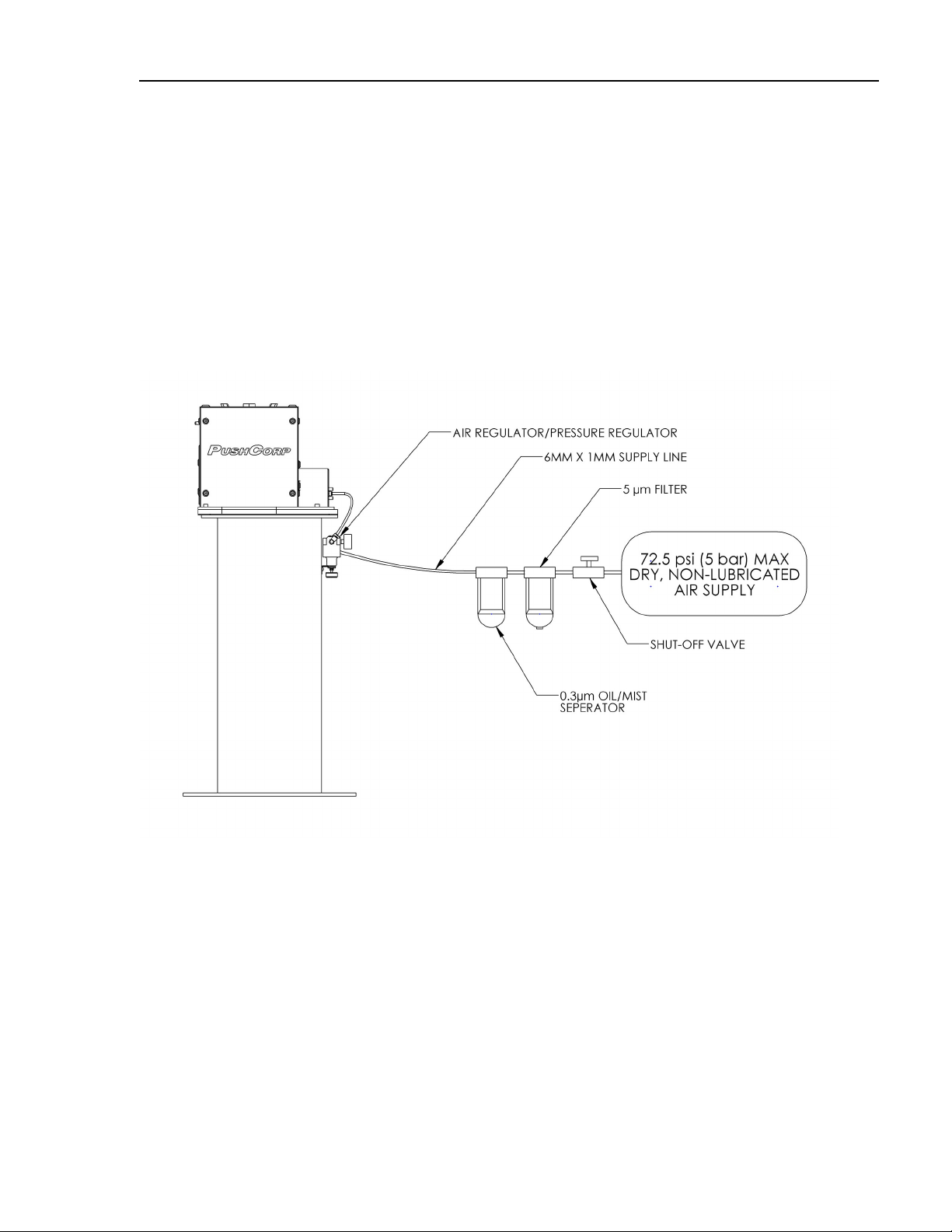
To operate the RPC100, electrical and pneumatic connections are required. The
electrical connection on the RPC100 is a male “A-code” M12 8pin connector. Power
as well as digital inputs and outputs are all fed through this single connection. The
pneumatic connection is a ¼” or 6mm line that connects to a solenoid valve. With a
24V signal the solenoid is actuated causing the c linder to extend. It is imperative
that the air connection is filtered, non-lubricated, and has air pressure ranging from
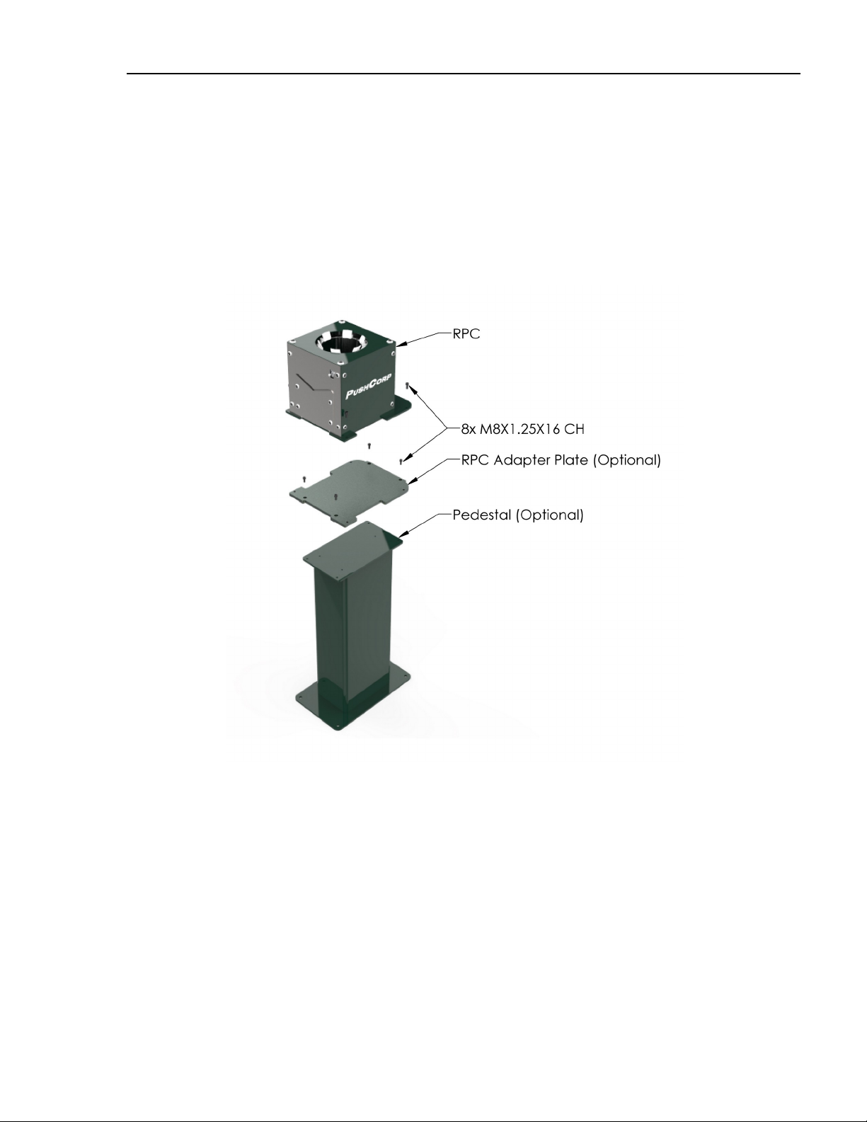
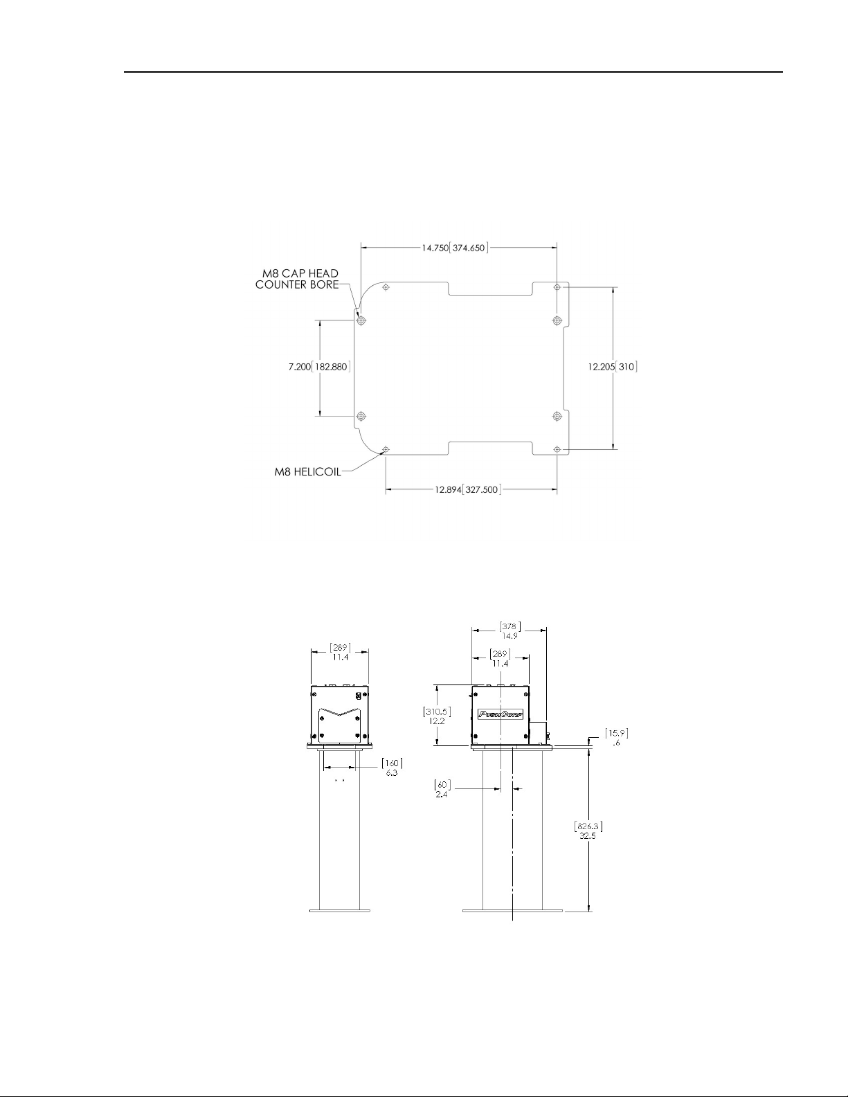
43.5 to 72.5 psi (3 – 5 bar). It is recommended that the RPC100 is securel mounted
to the RPC100 Base with the appropriate bracket both designed and manufactured
b PushCorp, Inc.
4

PUSHCORP, INC.
RPC100-75/125/150 Manual
3.0 Quick Start
This section contains step-b -step instructions on how to quickl get the RPC100 up
and running for a test of its capabilities. Complete details on all the features are
described in the sections that follow. It is recommended that the user read the entire
manual before operating to full understand all the aspects and features of the
RPC100.
Step 1: Carefull unpack the RPC100 and verif that all parts indicated
on the packing list are present and in good condition. If there is a
problem, please notif the factor immediatel so that corrective action
ma be promptl initiated.
Step 2: Securel attach adapter plate to the RPC100 plate as shown in
figure 1.
Step 3: Mount the RPC100 to the RPC100 adapter plate
Step 4:Connect a dr , non-lubricated, 5µm filtered 43.5 to 72.5 psi (3 to
5 bar) air suppl to the RPC100 per Section 4.2.
Step 5: Connect female “A-code” M12 8pin cable to the RPC100 unit
and hardwire the connections per figure 10 in Section 6
Please read the following sections to learn the full potential and features of the
PushCorp RPC100 Pad Changer Device.
5

PUSHCORP, INC.
RPC100-75/125/150 Manual
4.0 Installation
4.1 Mounting Process Equipment
While not necessar , it is recommended that the RPC100 is securel mounted atop
the RPC100 Pedestal with a PushCorp designed mounting bracket. The bracket is
mounted to the RPC100 Adapter Plate with four M8 cap head fasteners; the
RPC100 is then mounted to the bracket with four M8 cap heads.
6
Figure 1: RPC100 Mounting Assembl

PUSHCORP, INC.
RPC100-75/125/150 Manual
The bolt pattern on the adapter plate is designed for M8 fasteners with all tapped
through holes. The outline shown in Figure 2 shares its perimeter with the RPC100
and RPC100 Base plate. This is critical because it allows the discarded paper to fall
through without interfering with the operation of the pad changing device. There are
three cutouts that allow for the orientation of the blade to be configured based on
our cell la out. The unit will ship with it configured as shown in Figure 6.
7
Figure 2: RPC Adapter Plate
Figure 3: RPC Overall Dimensions

PUSHCORP, INC.
RPC100-75/125/150 Manual
4.2 Pneumatic Connection
The RPC100 requires a dr , non-lubricated, 5µm filtered, 43.5 to 72.5 psi (3 – 5 bar)
air suppl . Failure to provide suppl air to these specifications can degrade
performance and will void an warrant repairs concerning pneumatic components.
Filtered air is required since this actuates the c linder thus moving the paper into the
appropriate paper changing position. As a result, this component cannot tolerate
ANY foreign material in the suppl air. Additionall , a minimum 43.5 psi (3 bar) air
pressure must be maintained at the suppl air port for the device to operate within
published specifications. Operating at lower air pressure can cause inferior
performance and possibl failure.The pneumatic suppl s stem should be
configured as shown in Figure 4.
If water condensation is a problem in our air suppl s stem, an air dr er device is
highl recommended. The ideal solution is an industrial chiller dr er capable of
reducing the dew point to less than 32 F (0C). Moisture inside the c linder will cause
premature failure that will not be covered under warrant .
8
Figure 4: Pneumatic configuration

PUSHCORP, INC.
RPC100-75/125/150 Manual
The Suppl Line to the device should be 1/4 inch (wall thickness 3/64 inch) or 6mm
(wall thickness 1 mm) diameter flexible pol urethane tubing. The tubing should be
routed to the RPC100 such that there are no kinks. Before inserting the Suppl Line
into the air fitting, open the Shut-Off valve to blow out an contaminates which ma
be in the line. The tubing can now be pushed into the self-locking fitting located on
the side of the RPC100. Charge the Suppl Line with compressed air and verif that
there are no air leaks and that there is a minimum of 43.5 PSI (3 bar).
NOTE: PushCorp highly recommends the use of flexible polyurethane tubing
as opposed to nylon tubing. This is because nylon tubing tends to crimp shut
when it is bent. This severely limits air flow and can cause inadequate
pressure to the cylinder.
To remove the Suppl Line, first discharge all air pressure in the s stem, then while
pushing inward on the fitting's plastic ring, simultaneousl pull the tubing out. Cover
or plug the self-locking fitting an time the Suppl Line is not connected. This will
keep an contaminants from entering the RPC100.
9
Figure 5: RPC100 Air Connections

PUSHCORP, INC.
RPC100-75/125/150 Manual
5.0 Operation
After ensuring proper electrical and pneumatic connections, secure mounting, and a
magazine full of abrasive discs, the RPC100 is read to operate. The amount of
discs in the magazine varies based on the grit of the paper, but can be determined
b placing discs into the unit while the c linder is not pressurized. These can be
stacked until the reach the bottom of the six white guides at the top of the unit. A
t pical random orbital sander and force control setup can be seen in Figure 6.
If the sander does not have a sanding disc, the first step is to program a robot point
where the pad is parallel with the bottom of the white guides shown in Figure 7.
These guides will center the sanding pad due to its eccentricit and help ensure that
the pad and disc are concentric with each other.
Note: The magnetic sensors attached to the air c linder are set at the full retracted
(bottom sensor – pin 3) and extended position (top sensor – pin 4). If pin 4 is on then
the unit is out of paper.
10
Figure 6: RPC100 Full Assembl

PUSHCORP, INC.
RPC100-75/125/150 Manual
11
Figure 7: RPC100 Pad Retrieval - Retracted
Figure 8: RPC100 Pad Retrieval - Extended

PUSHCORP, INC.
RPC100-75/125/150 Manual
To actuate the air c linder that raises the magazine, a 24V signal is sent to the
pneumatic sensor via pin 6 of the electrical connector. This will raise the magazine
to allow for the disc to engage with the hook and loop pad.
When the abrasive is worn, these are the steps that must be taken to ensure its
removal. The removal process occurs using the blade shown below in Figure 9. The
blade can be adjusted depending on sanding disc grit/thickness to allow for a
complete transition through the channel. This height can be set using shim washers
shown below.
12
Figure 9: Shim Washer Stack Up

PUSHCORP, INC.
RPC100-75/125/150 Manual
The first robot point will be flat against the bod of the paper changer and tangent
with the blade’s edge.
Then, move the pad down towards the ground so the paper is halfwa into the blade
as shown in the Figure 8b. Next, create another point so the paper is ¾ of the wa
into the blade and the pad is at a roughl 5 degree angle. The final step will be a
quick downward motion maintaining the 5 degree angle. This is to prevent the paper
from getting pinched b the blade. The speed to achieve this can var based on grit,
but a good starting point is 75 mm/s.
13
Figure 10: RPC100 Pad Removal

PUSHCORP, INC.
RPC100-75/125/150 Manual
14
Figure 11: RPC100 Pad Removal
Figure 12: RPC100 Pad Removal

PUSHCORP, INC.
RPC100-75/125/150 Manual
To ensure the paper has been applied or removed properl a probe sensor is used
to validate the process. This is a spring loaded probe sensor, which is shown in
Figure 14. The pad must have a counter bore at its center to allow for proper sensor
detection. There are several off the shelf options that can be purchased from our
abrasive distributor. Please refer to the following table for necessar counter bore
size:
Orbit Size Counter Bore Diameter
0 9mm
9.5mm (3/8”) 20mm
4.8 mm (3/16”) 15mm
2.4 mm (3/32”) 13mm
15
Figure 13: RPC100 Pad Removal

PUSHCORP, INC.
RPC100-75/125/150 Manual
For the validation process a single point is programmed on the robot. This is done
without a disc on the backup pad. Program the point so that the touch probe is inside
of the counter bore of the backup pad as described above. You will want to center
this point with the rotation of the spindle shaft so that regardless of the eccentricit
the probe will not be touched. Then, If the pad has paper it will press the touch probe
and a 24V signal is sent to pin 5 of the electrical connection indicating that disc is
present. Otherwise, a signal will not be sent if there is no paper present.
16
Figure 14: RPC100 Sensor with Paper
Figure 15: RPC100 Sensor without Paper

PUSHCORP, INC.
RPC100-75/125/150 Manual
6.0 Electrical Connections
The electrical connection is located next to the pneumatic connection shown below
in Figure 16. To wire the connector and the sensors as described throughout the
manual, please refer to the wiring diagram shown below in Figure 17.
Wiring Diagram
1 24V
2 0V
3 Magnetic Sensor Bottom (IN)
4 Magnetic Sensor Top (IN)
5 Probe Sensor (IN)
6 Pneumatic Valve (OUT)
7 Not Used
8 Not Used
17
Figure 17: RPC100 Wiring Diagram
Figure 16: Male “A-code” M12 8pin Connector

PUSHCORP, INC.
RPC100-75/125/150 Manual
7.0 Technical Specifications
Disc Size: 3”,5”or 6”
Power: 24VDC 1.5A
Weight: 16.2 lbs. (7.4 kg)
Temperature: 0 to 122 F (10 to 50 C)
Humidit : 5% to 95%, Non-Condensing
Suppl air: Non-lubricated, Dr , 5mm Filtered, 43.5-72.5 psi (3-5 bar)
2 SCFM (56 l/min)
Specifications subject to change without notice. These values are based on measurements taken in a
laborator environment. Real-world results ma be degraded due to external factors be ond
PushCorp’s control.
Fastener Tightening Torque Specs
Torque Minimum Depth
Fastener Size in.-lbs. ft.-lbs. N·m in. mm
M8 x 1.25 348 29.0 39.3 0.33 8.4
18
This manual suits for next models
2
Table of contents
Other PushCorp Industrial Equipment manuals

PushCorp
PushCorp AFD1200 User manual

PushCorp
PushCorp AFD310 User manual

PushCorp
PushCorp SBS81 Series User manual

PushCorp
PushCorp AFD1240 User manual

PushCorp
PushCorp SWS100-3.7 User manual

PushCorp
PushCorp 620 Series User manual

PushCorp
PushCorp AFD1000 Series User manual

PushCorp
PushCorp AFD92 User manual
Popular Industrial Equipment manuals by other brands

Panasonic
Panasonic Aicure ANUP5255V2 Operation manual

ABB
ABB HT575445 Operation manual

Hammerhead
Hammerhead 100XT Operator's manual

PI
PI L-412.XX9232 Series user manual

Reliable
Reliable Double Interlock Preaction System D Instructions for installation, operation care and maintenance

Tecnodue
Tecnodue I.T.S. PT 500 operating manual