Zakład Wytwórczy Aparatów Elektrycznych Sp. z o.o.
9
mechanism, the surface of the earthing point has to be precisely cleaned. At the end of the earthing rail, a Ø13
mm hole has to be made for the fastening screw. After leveling the surface and lubricating it with the below
mentioned vaseline, the rail has to be attached to the earthing point, paying attention to precise tightening of
the screw.
3.3. Connection of control and power circuits.
The cables should be inserted into the housing of the operating mechanism through the gland at the bottom
of operating mechanism. The connection of the control cable's wires with the terminal strip of the operating
mechanism should be made in accordance with the switchgear's proper plan. The maximum cross-section of
wires connected to the terminal strip can be 4.0 mm2.
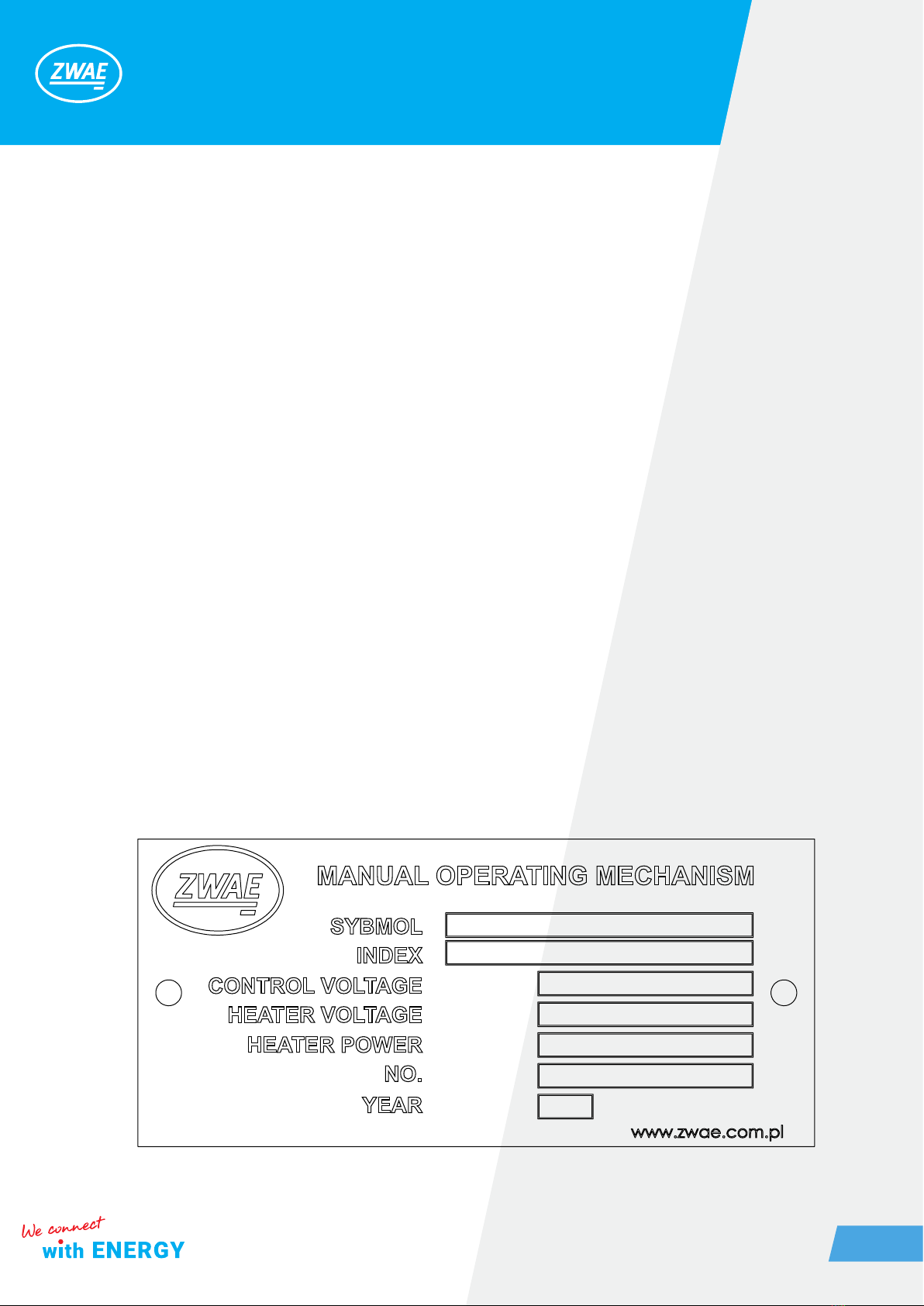
The electrical scheme is set individually, its paper version is supplied with the operating mechanism and its
number is indicated on the nameplate.
3.4. Test before rst run
Before putting the operating mechanism into service, the quality of its assembly and the correct interaction
with the apparatus must be checked. For that purpose, 5-10 shifts should be made using manual operating
lever, carefully observing the interaction of the parts. In a case of any irregularities in the operation of the oper-
ating mechanism or the apparatus cooperating with it, a re-adjustment of the respective assemblies should be
carried out and the tests should be repeated.
4. OPERATING MANUAL
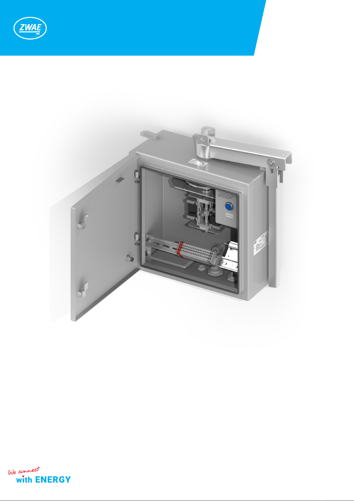
4.1. Maneuvering
In order to operate the operating mechanism manually the following steps should be done:
1. Applying voltage to the coil of electromagnetic lock by holding down the button * [4] (locking the electromag-
net in a voltage free condition prevents the operating mechanism from switching).
*If there is no locking electromagnet, one should pull and turn the tie rod of electromagnetic lock[9] from the "Locked"
position to the "Unlocked" position.
2. Raise the manual operating lever to place it parallelly [1].
3. Rotate the shaft causing the apparatus to switch
5. INSPECTIONS AND MAINTENANCE
5.1. Visual inspection
It is recommended to carry out visual inspections once a year and after each failure or short circuit in the
switchgear. These should be checked in particular: