Martin MX-1 User manual

MX-1
user manual
P/N 35000077

©1999 Martin Professional A/S, Denmark.
All rights reserved. No part of this manual may be
reproduced, in any form or by any means, without
permission in writing from Martin Professional A/S,
Denmark.
Printed in Denmark.
P/N 35000077, revision #990412-MA

MX-1 user manual 3
Introduction . . . . . . . . . . . . . . . . . . . . . . . . . . . . . . . . . . . . . . . .4
Safety precautions . . . . . . . . . . . . . . . . . . . . . . . . . . . . . . . . . . . . . . . . . . . . . 4
Unpacking . . . . . . . . . . . . . . . . . . . . . . . . . . . . . . . . . . . . . . . . . . . . . . . . . . . . 5
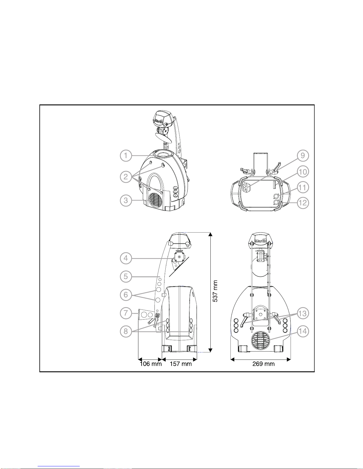
Parts key . . . . . . . . . . . . . . . . . . . . . . . . . . . . . . . . . . . . . . . . . . .6
Lamp installation . . . . . . . . . . . . . . . . . . . . . . . . . . . . . . . . . . . .7
To install a lamp in the MX-1 . . . . . . . . . . . . . . . . . . . . . . . . . . . . . . . . . . . . . . 7
AC power connection . . . . . . . . . . . . . . . . . . . . . . . . . . . . . . . .8
To change the voltage setting . . . . . . . . . . . . . . . . . . . . . . . . . . . . . . . . . . . . . 8
To install a plug on the mains lead . . . . . . . . . . . . . . . . . . . . . . . . . . . . . . . . . 9
Installation . . . . . . . . . . . . . . . . . . . . . . . . . . . . . . . . . . . . . . . .10
To rig the MX-1 . . . . . . . . . . . . . . . . . . . . . . . . . . . . . . . . . . . . . . . . . . . . . . . 10
DIP-switch settings . . . . . . . . . . . . . . . . . . . . . . . . . . . . . . . . .11
DMX address selection . . . . . . . . . . . . . . . . . . . . . . . . . . . . . . . . . . . . . . . . . 11
To set the DMX address . . . . . . . . . . . . . . . . . . . . . . . . . . . . . . . . . . . . . . . . 11
Special settings . . . . . . . . . . . . . . . . . . . . . . . . . . . . . . . . . . . . . . . . . . . . . . . 13
Data connection . . . . . . . . . . . . . . . . . . . . . . . . . . . . . . . . . . . .14
Recommended cable . . . . . . . . . . . . . . . . . . . . . . . . . . . . . . . . . . . . . . . . . . 14
Connections . . . . . . . . . . . . . . . . . . . . . . . . . . . . . . . . . . . . . . . . . . . . . . . . . 14
To connect the data link . . . . . . . . . . . . . . . . . . . . . . . . . . . . . . . . . . . . . . . . 15
Operation . . . . . . . . . . . . . . . . . . . . . . . . . . . . . . . . . . . . . . . . .16
Full DMX operation . . . . . . . . . . . . . . . . . . . . . . . . . . . . . . . . . . . . . . . . . . . . 16
1-channel DMX operation . . . . . . . . . . . . . . . . . . . . . . . . . . . . . . . . . . . . . . . 16
Stand-alone operation . . . . . . . . . . . . . . . . . . . . . . . . . . . . . . . . . . . . . . . . . . 17
To connect units for master / slave operation . . . . . . . . . . . . . . . . . . . . . . . . 17
Basic service . . . . . . . . . . . . . . . . . . . . . . . . . . . . . . . . . . . . . .18
Cleaning . . . . . . . . . . . . . . . . . . . . . . . . . . . . . . . . . . . . . . . . . . . . . . . . . . . . 18
To clean optical components . . . . . . . . . . . . . . . . . . . . . . . . . . . . . . . . . . . . 18
To clean the fan and air vents . . . . . . . . . . . . . . . . . . . . . . . . . . . . . . . . . . . . 19
Replacing fuses . . . . . . . . . . . . . . . . . . . . . . . . . . . . . . . . . . . . . . . . . . . . . . . 19
To replace the main fuse . . . . . . . . . . . . . . . . . . . . . . . . . . . . . . . . . . . . . . . . 19
To replace the secondary fuse . . . . . . . . . . . . . . . . . . . . . . . . . . . . . . . . . . . 19
Troubleshooting . . . . . . . . . . . . . . . . . . . . . . . . . . . . . . . . . . .20
DMX protocol . . . . . . . . . . . . . . . . . . . . . . . . . . . . . . . . . . . . . .21
Specifications . . . . . . . . . . . . . . . . . . . . . . . . . . . . . . . . . . . . .22

4 Introduction MX-1 user manual
I
NTRODUCTION
1
Thank you for selecting the Martin MX-1. The MX-1 is an automated profile
spotlight that employs a 250 watt halogen lamp. It provides strobe effects,
continuous electronic dimming, 18 color/gobo effects, a moving-mirror with 230°
of pan and 76° of tilt, adjustable focus, a 16° beam angle, and a variety of control
options.
The MX-1 is not for household use. It is not for children: it presents risks of injury
due to electric shock, burns, falls, high-intensity light, and fire. For safe operation,
read this manual before powering or installing the fixture, follow the safety
precautions listed below, and observe all warnings printed in this manual and on
the fixture. If you have questions about how to operate the fixture safely, please
contact your Martin dealer or call the Martin 24-hour service hotline for
assistance.
SAFETY PRECAUTIONS
• ALWAYS disconnect the fixture from AC power before opening the fixture or
removing any part.
• ALWAYS keep combustible materials (for example fabric, wood, paper) at
least 10 centimeters (4 inches) away from the fixture.
• ALWAYS ground (earth) the fixture electrically.
• ALWAYS allow the lamp to cool at least 5 minutes before removing the lamp
assembly.
• ALWAYS, when suspending the fixture above ground level, secure it with an
approved safety cable.
• ALWAYS refer service to a qualified technician.
• ALWAYS provide a minimum clearance of 10 centimeters (4 inches) around
the fan and air vent.
• ALWAYS block access below the work area when rigging, derigging, or
servicing fixtures.
• NEVER place flammable materials anywhere near the fixture.
• NEVER expose the fixture to rain or moisture.

MX-1 user manual Introduction 5
• NEVER illuminate surfaces within 0.3 meters (12 inches) of the fixture.
• NEVER operate the fixture if the ambient temperature (Ta) exceeds 40° C
(104° F).
• NEVER place filters or other objects over the lens or mirror.
• NEVER stare directly into the light.
• NEVER operate the fixture without all parts installed.
• NEVER modify the fixture or install other than genuine Martin parts.
UNPACKING
The packing material is carefully designed to protect the fixture during shipment
- always use it to transport the fixture.
The MX-1 comes with:
• 1 3-meter, 3-wire IEC power cable
• 1 user manual
Important! The mirror assembly is secured for transport with a plastic tie.
Cut and remove the tie before use.

6 Parts key MX-1 user manual
P
ARTS
KEY
2
1 focus lens
2 cover locks
3 air vent
4 mirror assembly
5 pan/tilt arm
6 safety cable holes
7 mounting bracket
8 air vents
9 AC input & main
fuse
10 DIP-switch
11 data output
12 data input
13 swivel locks
14 cooling fan

MX-1 user manual Lamp installation 7
L
AMP
INSTALLATION
3
The MX-1 uses a 24V, 250W ELC halogen lamp. Two models are available, an
economical 300 hour lamp from Philips and a high-output 50 hour lamp from
Osram. Installing any other lamp may damage the fixture.
Allow the lamp to cool for at least 5 minutes before packing and moving the
fixture. To avoid possible damage, remove the lamp when shipping the fixture.
Warning! Always disconnect the fixture from AC power and allow it to
cool for 5 minutes before installing the lamp.
To install a lamp in the MX-1
1 Disconnect the fixture from AC power. If replacing a hot lamp, allow it to cool
for 5 minutes before removing the cover. The lamp cools faster with the cover
in place.
2 Release the 4 cover locks by turning them a quarter-turn counterclockwise.
Lift the cover straight off.
3 To remove the lamp, grasp it by the reflector and pull it out of the holder. Pull
the socket straight back off the metal pins. Do not pull the wires.
4 Push the socket fully onto the pins of the new lamp.
5 Gently push the lamp into the holder until it snaps into place.
6 Replace the top cover. To lock the 4 cover locks, turn them a half to a quarter
turn clockwise until you feel them click.
Do not overtighten
.

8 AC power connection MX-1 user manual
AC
POWER
CONNECTION
4
Warning! For safe operation, the fixture must be grounded (earthed).
Important! Check voltage setting before applying power. Do not connect
the MX-1 to an electrical dimmer system: doing so can damage
the electronics.
Before use verify that the fixture’s power supply is correctly tapped for the local
AC voltage. The default voltage setting is printed on the serial number label near
the AC input. The “EU” version may be set to 230 or 245 V AC and the “US”
version may be set to 110 or 120 V AC. Use the setting that is closest to the local
supply voltage.
To change the voltage setting
1 Disconnect the fixture from AC power.
Release the 4 cover locks by turning
them a quarter-turn counterclockwise.
Lift the cover straight off.
2 Locate and disconnect plug PL124 on
the back edge of the printed circuit
board. It has red, yellow, and blue
wires.
3 To select 230 V AC (EU version) or 110
V AC (US version), flip and move the
plug
up
so that the
red
wire connects
to the
top
pin.
4 To select 245 V AC (EU version) or 120
V AC (US version), flip and move the
plug
down
so that the
red
wire
connects to the
bottom
pin.
5 Replace the top cover before applying
power.
red
red
Setting for
110 V (US) / 230 V (EU)
Setting for
120 V (US) / 245 V (EU)

MX-1 user manual AC power connection 9
To install a plug on the mains lead
The fixture’s mains lead must be fitted with a grounding-type cord cap that
fits your power distribution cable or outlet. Consult a qualified electrician if
you have any doubts about proper installation.
Important! Verify that the feed cables are undamaged and rated for the
current requirements of all connected devices before use.
• Following the cord cap manufacturer’s instructions, connect the yellow and
green wire to ground (earth), the brown wire to live, and the blue wire to
neutral. The table below shows some pin identification schemes.
Wire Pin Marking Screw color
brown live “L” yellow or brass
blue neutral “N” silver
yellow/green ground green

10 Installation MX-1 user manual
I
NSTALLATION
5
The MX-1 can be fastened directly to a suitable surface or to a rigging clamp by
means of its adjustable mounting bracket and it can be placed at an angle directly
on the stage or floor using the mounting bracket as a floor stand.
Do not lay the fixture flat on its pan/tilt arms. For maximum lamp life, do not
place the fixture directly on or beside a speaker cabinet or other source of strong
vibrations.
Warning! Block access below the work area before proceeding.
Warning! Always use a secure means of secondary attachment.
To rig the MX-1
1 Verify that the clamp is undamaged and can handle the weight of the fixture.
Bolt the clamp securely to the bracket with a grade 8.8 (minimum) M12 bolt
and lock nut, or as recommended by the clamp manufacturer, through the 13
mm hole in the center of the mounting bracket.
2 If fastening the bracket directly to the structure, make sure that the
attachment hardware is adequate to hold the fixture securely. The four 6.2 mm
holes and/or the 13 mm hole in the mounting bracket may be used.
3 Verify that the structure can support the weight of all installed fixtures,
clamps, cables, auxiliary equipment, etc.
4 Working from a stable platform, clamp or fasten the fixture to the structure.
5 Install a safety cable that can hold at least 10 times the weight of the fixture
through/over the support and through a hole in the pan/tilt arm.
6 Loosen the swivel locks and tilt the fixture to the desired angle. Turn the
swivel locks clockwise to tighten.
7 If a swivel lock does not tighten fully, pull the handle out, turn it
counterclockwise, and retighten. Repeat as necessary.
8 Verify that the fixture is located at least 0.3 meters (12 in.) away from the
surface to be illuminated and at least 0.1 meters (4 in.) from any combustible
materials. Verify that the clearance around the fan and air vents is at least 0.1
meters (4 in.).

MX-1 user manual DIP-switch settings 11
DIP-
SWITCH
SETTINGS
6
This section describes how to select the control address and special settings using
the DIP-switch on the end panel.
DMX ADDRESS SELECTION
If the MX-1 is to be used with a DMX protocol controller, then the DIP-switch
must be set to the DMX control address. The address, also known as the start
channel, is the first channel used to receive instructions from the controller. The
MX-1 uses 6 channels for full DMX operation. For independent control, each
fixture must be assigned its own address and non-overlapping control channels.
Two MX-1s may share the same address only if they are to respond identically:
they will receive the same instructions and individual control will not be possible.
To set the DMX address
1 Select an address for the fixture on your controller.
2 Look up the DIP-switch setting for the address on page 12.
3 Set pins 1 through 9 to the ON (1) or OFF (0) position as listed in the table.
4 Set pin 10 to the OFF position.
5 Set pin 11 to the OFF position for full 6-channel DMX operation or to the ON
position for 1-channel DMX operation.

12 DIP-switch settings MX-1 user manual
DIP-SWITCH ADDRESS TABLE
Find the address in the table below. Read the settings for pins 1 - 5 to the left and
read the settings for pins 6 - 9 above the address. “0” means OFF and “1” means
ON.
Important! Pins 10 and 11 must be OFF for full DMX control. Pin 10 must
be OFF and pin 11 must be ON for 1-channel DMX control.
',306ZLWFK#6HWWLQJ
3# #2))
4# #21
&<3333333344444444
&;3333444433334444
&:3344334433443344
&93434343434343434
&4 &5 &6 &7 &8
3 3 3 3 3 65 97 <9 45; 493 4<5 557 589 5;; 653 685 6;7 749 77; 7;3
4 3 3 3 3 4 66 98 <: 45< 494 4<6 558 58: 5;< 654 686 6;8 74: 77< 7;4
3 4 3 3 3 5 67 99 <; 463 495 4<7 559 58; 5<3 655 687 6;9 74; 783 7;5
4 4 3 3 3 6 68 9: << 464 496 4<8 55: 58< 5<4 656 688 6;: 74< 784 7;6
3 3 4 3 3 7 69 9; 433 465 497 4<9 55; 593 5<5 657 689 6;; 753 785 7;7
4 3 4 3 3 8 6: 9< 434 466 498 4<: 55< 594 5<6 658 68: 6;< 754 786 7;8
3 4 4 3 3 9 6; :3 435 467 499 4<; 563 595 5<7 659 68; 6<3 755 787 7;9
4 4 4 3 3 : 6< :4 436 468 49: 4<< 564 596 5<8 65: 68< 6<4 756 788 7;:
3 3 3 4 3 ; 73 :5 437 469 49; 533 565 597 5<9 65; 693 6<5 757 789 7;;
4 3 3 4 3 < 74 :6 438 46: 49< 534 566 598 5<: 65< 694 6<6 758 78: 7;<
3 4 3 4 3 43 75 :7 439 46; 4:3 535 567 599 5<; 663 695 6<7 759 78; 7<3
44343 44 76 :8 43: 46< 4:4 536 568 59: 5<< 664 696 6<8 75: 78< 7<4
3 3 4 4 3 45 77 :9 43; 473 4:5 537 569 59; 633 665 697 6<9 75; 793 7<5
4 3 4 4 3 46 78 :: 43< 474 4:6 538 56: 59< 634 666 698 6<: 75< 794 7<6
34443 47 79 :; 443 475 4:7 539 56; 5:3 635 667 699 6<; 763 795 7<7
4 4 4 4 3 48 7: :< 444 476 4:8 53: 56< 5:4 636 668 69: 6<< 764 796 7<8
3 3 3 3 4 49 7; ;3 445 477 4:9 53; 573 5:5 637 669 69; 733 765 797 7<9
43334 4: 7< ;4 446 478 4:: 53< 574 5:6 638 66: 69< 734 766 798 7<:
3 4 3 3 4 4; 83 ;5 447 479 4:; 543 575 5:7 639 66; 6:3 735 767 799 7<;
4 4 3 3 4 4< 84 ;6 448 47: 4:< 544 576 5:8 63: 66< 6:4 736 768 79: 7<<
33434 53 85 ;7 449 47; 4;3 545 577 5:9 63; 673 6:5 737 769 79; 833
4 3 4 3 4 54 86 ;8 44: 47< 4;4 546 578 5:: 63< 674 6:6 738 76: 79< 834
3 4 4 3 4 55 87 ;9 44; 483 4;5 547 579 5:; 643 675 6:7 739 76; 7:3 835
44434 56 88 ;: 44< 484 4;6 548 57: 5:< 644 676 6:8 73: 76< 7:4 836
3 3 3 4 4 57 89 ;; 453 485 4;7 549 57; 5;3 645 677 6:9 73; 773 7:5 837
4 3 3 4 4 58 8: ;< 454 486 4;8 54: 57< 5;4 646 678 6:: 73< 774 7:6 838
34344 59 8; <3 455 487 4;9 54; 583 5;5 647 679 6:; 743 775 7:7 839
4 4 3 4 4 5: 8< <4 456 488 4;: 54< 584 5;6 648 67: 6:< 744 776 7:8 83:
3 3 4 4 4 5; 93 <5 457 489 4;; 553 585 5;7 649 67; 6;3 745 777 7:9 83;
43444 5< 94 <6 458 48: 4;< 554 586 5;8 64: 67< 6;4 746 778 7:: 83<
3 4 4 4 4 63 95 <7 459 48; 4<3 555 587 5;9 64; 683 6;5 747 779 7:; 843
4 4 4 4 4 64 96 <8 45: 48< 4<4 556 588 5;: 64< 684 6;6 748 77: 7:< 844

MX-1 user manual DIP-switch settings 13
SPECIAL SETTINGS
The DIP-switch is used to select special personality options when the fixture is
operated in stand-alone and master/slave mode.
Lamp life can be extended beyond the stated average hours by reducing the lamp
voltage slightly. Set DIP-switch pin 12 to ON for longer lamp life, or OFF for full
output intensity.
Important! Pin 10 must be ON to enable special settings on pins 1 - 9.
Pin Setting Effect
1ON Music trigger
OFF Automatic trigger
2ON Stand-alone “master” fixture
OFF Stand-alone “slave” fixture
3 ON/OFF Reserved, no effect
4ON Slow mirror movement (set on master fixture)
OFF Fast mirror movement
5ON Wide mirror movement (set on master fixture)
OFF Narrow mirror movement
6ON Random effect wheel position (set on slave fixture)
OFF Effect wheel position same as master
7ON Inverted effect wheel position (set on slave fixture)
OFF Normal effect wheel position
8ON Inverted tilt (set on slave fixture)
OFF Normal tilt
9ON Inverted pan (set on slave fixture)
OFF Normal pan
10 ON Enable special settings with pins 1 - 9
OFF Enable DMX address with pins 1 - 9
11 ON 1-channel mode on
OFF 1-channel mode off
12 ON Reduced power / longer lamp life
OFF Full power / maximum intensity

14 Data connection MX-1 user manual
D
ATA
CONNECTION
7
This section describes how to connect fixtures to a controller.
RECOMMENDED CABLE
A reliable data connection begins with the right cable. Standard microphone cable
cannot transmit DMX data reliably over long runs. For best results, use cable
specifically designed for RS-485 applications. Your Martin dealer can supply high
quality cable in various lengths.
CONNECTIONS
The MX-1’s XLR data sockets are wired with pin 1 to ground, pin 2 to signal -
(cold), and pin 3 to signal + (hot). This is the standard pin assignment for DMX
devices.
One or more adaptor cables may be required to connect the MX-1 to the controller
and/or other lights because many devices have 5-pin connectors and others may
have reversed signal polarity, that is, pin 2 hot and pin 3 cold.
Phase-Reversing
Adaptor
Male Female
1
2
3
1
2
3
3-pin to 3-pin
P/N 11820006
Adaptor
Male Female
1
2
3
4
5
1
2
3
5-pin to 3-pin
P/N 11820005
Adaptor
Male Female
1
2
3
1
2
3
4
5
3-pin to 5-pin
P/N 11820004

MX-1 user manual Data connection 15
To connect the data link
1 Connect a data cable to the controller’s data output. If controller has a 5-pin
female data output, use a 5-pin male to 3-pin female adaptor cable (P/N
11820005).
2 Lead the data cable from the controller to the first fixture. Plug the cable into
the fixture’s data input.
3 Connect the output of the fixture closest to the controller to the input of the
next fixture. If connecting to a fixture with reversed-polarity (pin 3 cold),
insert a phase-reversing cable between the two fixtures.
4 Continue connecting fixtures output to input. Up to 32 devices may be
connected on a serial link.
5 Terminate the link by inserting a male termination plug (P/N 91613017) into
the data output of the last fixture. A termination plug is simply an XLR
connector with a 120 ohm, 0.25 W resistor soldered across pins 2 and 3.
Male XLR
1
2
3
Male
P/N 91613017
120
Female XLR
1
2
3
Female
120
Termination PlugTermination Plug
P/N 91613018

16 Operation MX-1 user manual
O
PERATION
8
FULL DMX OPERATION
For DMX operation, the MX-1 must be connected to a DMX controller as
described under “Data connection” on page 14 and its DIP-switch must be set to
the control address as described on page 11.
DMX CHANNEL DESCRIPTION
See also the DMX protocol on page 21.
Channel 1 controls the light intensity and the strobe rate. It also allows you to
execute a “stand-alone” program with random pan/tilt movement using automatic
or music trigger.
All mechanical effects are reset to a home position when the fixture is powered
up; they can also be reset from the controller by sending a reset command on
channel 1.
Channel 2 is not used by the MX-1.
Channel 3 controls the position of the color/gobo effect wheel. When set to full
(DMX 255, 100 percent), the wheel moves to random positions using the trigger
selected on channel 1.
The mirror position, pan and tilt, is controlled on channels 4 and 5.
Channel 6 controls pan and tilt speed, allowing you to vary the movement speed
with controllers without cross-fade times. If your controller has cross-faders, and
you use them, then set channel 6 to the “tracking” speed (DMX 0, 0 percent).
1-CHANNEL DMX OPERATION
The MX-1 may be operated in single-channel mode with the optional MC-1 or
any DMX controller connected as described on page 14. If using the MC-1
controller, set the DMX address to channel 1. If using a DMX controller, any
channel may be assigned and set using DIP-switch pins 1 - 9.
The DIP-switch must be set with pin 10 off and pin 11 ON. Lamp power can be
set with pin 12 (see page 13).

MX-1 user manual Operation 17
The single-channel controllable functions are shown below.
STAND-ALONE OPERATION
The MX-1 automatically begins to operate in stand-alone mode with music
trigger - regardless of the DIP-switch settings - if there is no control signal.
The operation of single and “slave” units can be modified using the special DIP-
switch settings as described under “Special settings” on page 13.
MASTER / SLAVE OPERATION
Multiple MX-1s can be connected together for synchronized “master/slave”
operation in which the slaves mimic the behavior of the master.
In order to operate in this mode, the MX-1s must be connected together. One
fixture must be selected to be the master (DIP-switch 2 ON) and the others must
be set as slaves (DIP-switch 2 OFF).
Important! Only 1 fixture can be the master: errors and damage can occur
if there is more than 1 control signal on the data link.
To connect units for master / slave operation
1 Connect the output of one MX-1 to the input of the next MX-1.
2 Connect additional MX-1s output to input. Up to 32 may be connected.
3 Terminate the link on both ends by inserting a female termination plug into
the data input of the first fixture and a male termination plug into the data
output of the last fixture. A termination plug is simply an XLR connector with
a 120 ohm, 0.25 W resistor soldered across pins 2 and 3.
DMX value Percent Function
0 - 10
11 - 20
21 - 80
81 - 115
116 - 140
141 - 175
176 - 210
211 - 255
0 - 4
5 - 7
8 - 31
32 - 45
46 - 55
56 - 68
69 - 82
83 - 100
Blackout (light off)
Open (light on)
Strobe
Random action with slow music trigger
Random action with medium music trigger
Random action with fast music trigger
Random action with random music trigger
Manual trigger area, crossover at 240 (94%)

18 Basic service MX-1 user manual
B
ASIC
SERVICE
9
The MX-1 requires simple routine maintenance. The maintenance schedule
depends heavily on the operating environment; please consult a Martin service
technician for recommendations.
Any service procedure not described here should be referred to a qualified
technician.
Important! Excessive dust, grease, and smoke fluid buildup degrades
performance and causes overheating and damage to the
fixture that is not covered by the warranty.
Warning! Disconnect the fixture from AC power before removing any
cover.
CLEANING
To clean optical components
Use care when cleaning optical components. The surface of the color filters is
fragile and small scratches may be visible.
1 Disconnect the fixture from AC power and allow the components to cool
completely.
2 Release the 4 cover locks by turning them a quarter-turn counterclockwise.
Lift the cover straight off.
3 Blow or vacuum away loose dust. Remove residues from lenses and filters
with a soft cloth or cotton swabs wetted with isopropyl alcohol. Regular glass
cleaner may also be used, but no residues may remain.
4 Rinse with distilled water. Mixing the water with a small amount of wetting
agent such as Kodak Photoflo will help prevent streaking and spotting.
5 Dry with a clean, soft and lint-free cloth or blow dry with compressed air.
6 Replace the top cover. To lock the 4 cover locks, turn them a half to a quarter
turn clockwise, until you feel them click.
Do not overtighten
.

MX-1 user manual Basic service 19
To clean the fan and air vents
To maintain adequate cooling, dust must be cleaned from the fan and air vents
periodically.
1 Remove the data and power cables and stand the fixture on end.
2 Remove dust and dirt from the fan blades and vent grills using a soft brush,
cotton swab, vacuum, or compressed air.
REPLACING FUSES
The MX-1 has 2 fuses. The main fuse holder is built in to the mains input socket.
The secondary fuse is located on the printed circuit board.
Warning! Never replace fuses with ones of a different rating!
To replace the main fuse
1 Unplug the mains cable from the input socket. Pry open the fuse holder and
remove the fuse.
2 Replace the fuse with one of the same type. The fuse rating is listed on serial
number label.
To replace the secondary fuse
1 Disconnect the fixture from AC power. Release the 4 cover locks by turning
them a quarter-turn counterclockwise. Lift the cover straight off.
2 The fuse is located right behind the data input connector. Pry out the
defective fuse and replace it with one of the same rating.
3 Replace the cover before applying power.

20 Troubleshooting MX-1 user manual
T
ROUBLESHOOTING
10
Problem Probable cause(s) Remedy
One or more of the fixtures is
completely dead. No power to fixture. Check that power is switched on
and cables are plugged in.
Primary fuse blown. Replace fuse.
Secondary fuse blown. Replace fuse.
Fixtures reset correctly but all
respond erratically or not at all
to the controller.
The controller is not connected. Connect controller.
XLR pin-out of the controller
does not match pin-out of the
first fixture on the link (i.e.
signal is reversed).
Install a phase-reversing cable
between the controller and the
first fixture on the link.
Fixtures reset correctly but some
respond erratically or not at all
to the controller.
Bad data link connection Inspect connections and cables.
Correct poor connections.
Repair or replace damaged
cables.
Data link not terminated with
120Ω termination plug. Insert termination plug in output
jack of the last fixture on the
link.
Incorrect addressing of the
fixtures. Check DIP-switch settings.
One of the fixtures is defective
and disturbs data transmission
on the link.
Bypass one fixture at a time
until normal operation is
regained: unplug both
connectors and connect them
directly together. Have the
defective fixture serviced by a
qualified technician.
An effect fails to reset correctly. The effect requires mechanical
adjustment. Contact Martin technician for
service.
No light. Lamp missing or blown Disconnect fixture and replace
lamp.
Lamp cuts out intermittently. Fixture is too hot. Allow fixture to cool.
The transformer setting does not
match local AC voltage. Check AC setting.
Table of contents
Other Martin Spotlight manuals

Martin
Martin MAC III PERFORMANCE User manual

Martin
Martin MAC III AirFX User manual

Martin
Martin MAC III PERFORMANCE User manual

Martin
Martin MX-4 User manual

Martin
Martin MAC 500 User manual

Martin
Martin MAC Quantum Profile Setup guide

Martin
Martin MAC Encore Performance User manual

Martin
Martin CX-2 User manual

Martin
Martin Mania SCX600 User manual
Popular Spotlight manuals by other brands

Larson Electronics
Larson Electronics HID-X970-SA user manual

Larson Electronics
Larson Electronics Golight Stryker GL-30064ST instruction manual

Philips
Philips SmartSpot 57977/31/16 Specifications

Philips
Philips ColorBurst 6 Product guide

Shehds
Shehds LED Spot 100W Light user manual

American DJ
American DJ Pinspot LED BP Specifications