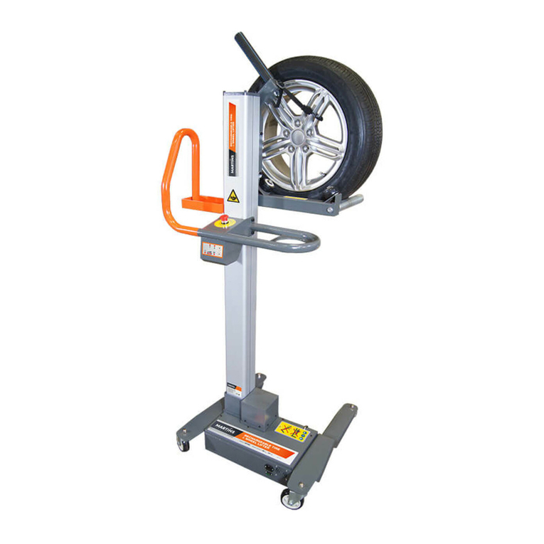
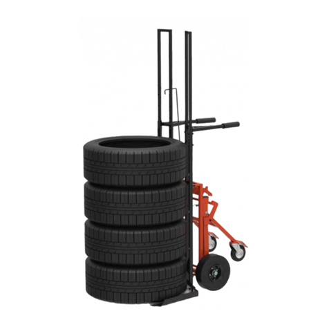
MARTINS Industries MTWL User manual

1
INSTRUCTIONS ORIGINALES
WHEEL LIFTER
MTWL
MANUAL
M A R T I N S I N D U S T R I E S .C O M

2
INSTRUCTIONS ORIGINALES
ENGLISH 02 / FRANÇAIS 29 / DEUTSCH 48

3
INSTRUCTIONS ORIGINALES
TABLE OF CONTENTS
1. INTRODUCTION............................................................................................................................................................. 4
1.1. WARRANTY TERMS .................................................................................................................................................. 4
1.2. SECURITY.............................................................................................................................................................. 5
1.3. SPECIAL WARNINGS................................................................................................................................................. 6
1.4. PRECAUTIONAL AND ORGANIZATIONAL ACTIONS ............................................................................................................. 6
2. TECHNICAL DATAS......................................................................................................................................................... 7
2.1. SOLLEVATORE........................................................................................................................................................ 7
2.2. POWER SUPPLY CABLE............................................................................................................................................. 7
3. TRANSPORT AND ASSEMBLING......................................................................................................................................... 8
4. USE ........................................................................................................................................................................ 10
4.1 BATTERIES CHARGE............................................................................................................................................... 10
4.2 CONTROLS AND USE INSTRUCTIONS........................................................................................................................... 11
4.3 LED LIGHTS SIGNALS.............................................................................................................................................. 12
5. MANTEINANCE ........................................................................................................................................................... 13
5.1. CLEANING ........................................................................................................................................................... 14
5.2. POWER SUPPLY CABLE CONTROL.............................................................................................................................. 14
5.3. WHEELS CHECK FOR TRANSPORT.............................................................................................................................. 14
5.4. EMERGENCY BUTTON CONTROL ................................................................................................................................ 14
5.5. FORK ROLLERS GREASING....................................................................................................................................... 15
5.6. TRAPEZOID SCREW AND RUNNERS GREASING .............................................................................................................. 16
5.7. BATTERIES REPLACEMENT ...................................................................................................................................... 17
6. BREAKDOWN CAUSES OR INTERRUPTION .......................................................................................................................... 18
7. DISPOSAL.................................................................................................................................................................. 19
8. STICKERS ON WHEELIFTER ............................................................................................................................................ 19
9. SECURITY CONTROLS SUMMARY SHEET ............................................................................................................................ 21
10. ELECTRICAL SCHEME.................................................................................................................................................. 22
11. EXPLODED VIEW ........................................................................................................................................................ 23

4
INSTRUCTIONS ORIGINALES
1. INTRODUCTION
Wheelifter 3473 is designed for the handling of the tire during the operations of assembly and
disassembly on the vehicle .Carefully read and follow the operating instructions in any work
situation, in order to avoid the damage and the risks deriving from the use of the equipment.
The Tire lifter Wheelifter 3473 is designed exclusively for lifting, lowering and transporting tires
for cars inside garages or tire replacement centers. The equipment should not be used in the
presence of explosive atmospheres .
Any use of the lift, which is not as specified in this manual is to be considered improper.
For a proper use of the equipment, it is recommended and it is considered necessary that
operator follows all instructions reported in this manual and that inspections and maintenance
are executed as set in the manual.
TECNOLUX s.r.l. will not be responsible in any way for damage or injury that are the
consequence of improper use of the equipment.
1.1. WARRANTY TERMS
Warranty terms are applied according to sale contract. The warranties and liability for personal
injury and / or material will expire if at least one of the following points occurs:
a) Misuse
b) Incorrect assembling
c) Maintenance and inspection of the equipment not correctly performed
d) The lift is used with protective devices that are not working or not properly installed
e) Instructions regarding the handling, assembly, maintenance and use are not followed
f) Parts subject to wear and / or deterioration are not replaced
g) Damage caused by agents and / or external causes or natural events

5
INSTRUCTIONS ORIGINALES
1.2. SECURITY
It is strictly forbidden the use the lift to unqualified people, people who do not know the
operating instructions of use and who have not read the manual. Using the lift, operator must
be aware of the basic safety standards .
The safety and operating instructions specified in this manual should be considered in addition
to the safety rules already set out for the place where the lift is in use.
For a safe use of the lift it is necessary to observe the following points:
a) The lift must be used only for the purposes for which it was conceived. It means that it
has to be used to lower or lift the wheel during mounting or dismounting it
b) Defects , non-compliance, malfunction must be reported and corrected immediately
c) If you find any defects, malfunctions or non-compliance, the lift should not be used until
these have been rectified .
d) Make sure that the lifter is working correctly after the assembly and initial operation .
e) When charging the battery make sure that the power cord is not in corridors or transit
area
f) Do not use and / or operate the lift in explosive atmospheres
g) Before you lift or lower the load, ensure that the tire is stable and well supported so that
it cannot fall .
h) Lower the tire completely before transporting
i) Use the lift only on flat floors and free of obstructions
j) Ensure that the use of the lift will not cause damage to other people
k) Keep the area free where the lift is used from obstacles
l) Do not enter into movement area of the lift
m) Do not exceed the allowed maximum loading
n) Perform lifting, lowering and transporting without sudden movements
o) Repairs on the lift can be operated only by qualified persons
It is complusory that operators who use the lift are informed concerning workplace safety, risks
prevention, lift operation and they have read, understood and accepted by signature of the
instructions and warnings in this paragraph.

6
INSTRUCTIONS ORIGINALES
1.3. SPECIAL WARNINGS
Before starting any maintenance or repair, disconnect the wheelifter from any power supply.
Take particular care not to mix up, confuse or incorrectly connect any electrical connection.
Take care not to come into contact with the battery pholes! Protect them and make sure they
are electrically isolated before handling the batteries.
Before opening the compartment containing the electrical equipment, the engine, make sure
that emergency button is pressed.
Before working on any electrical or mechanical parts or movement parts (eg motor, pulleys,
belts, etc.), disconnect the batteries and make sure that the lift can not accidentally come into
operation.
1.4. PRECAUTIONAL AND ORGANIZATIONAL ACTIONS
The operating instructions given in this manual must be kept in a place near the area of use of
the lift and accessible at any time.
In addition to these operating instructions and safety rules, all other rules relating to the
prevention of and protection from risks should be considered and implemented.
It is advisable to monitor the operators to ensure they are operating in accordance with the
safety standards and that they are using all safety devices required.
Make sure all safety instructions and usage on the lift are clearly readable.
Do not make any modifications to the lift without the approval of the manufacturer .
Use only original spare parts.
Perform periodic inspections as indicated in the manual.
In case of detected malfunction, immediately turn off the lift and make sure that it can not be
used. Repair the fault as soon as possible .

7
INSTRUCTIONS ORIGINALES
2. TECHNICAL DATAS
2.1. WHEEL LIFTER
TECHNICAL DATAS
M.U.
Width
mm
755
Length
mm
730
Heigth
mm
1710
Working height
mm
1100
Maximum height at wheel hub
mm
1400 *
Weight
Kg
55
Maximum speed
m/sec
0,1 (circa)
Maximum loading
kg
50
Operational temperature
°C
Min –5
Max +45
Batteries
Nr
2
Bat. Voltage
V
24
Bat. Capacity
Ah
12
Charge tension
V ac
220
* the data is connected to tire dimensions
2.2. POWER SUPPLY CABLE
The lift is equipped with a power cord to charge the batteries.
CABLE FEATURES
M.U.
Lenght
mm
2000
Cable type
-
Three poles cable 3x0,75 mm2
Plug
-
Europe type (CEE7/VII)
Outlet
-
IEC C13IEC
Working tension
V
250
Nominal power
A
16
Protection level
--
IP 20
External coating
-
PVC
Outlet cable
-
angled

8
INSTRUCTIONS ORIGINALES
3. TRANSPORT AND ASSEMBLING
Wheelifter 3473 is delivered packed in a carton box on a pallet. It is required a suitable means
of handling (such as a transpallet)
Inside the box you will find:
1) The main body (composed by the base, column, handle)
2) The brackets with wheels
3) The lifting forks
The assembly of parts must be carried out according to the following scheme (Figure 1)
Figure 1 - Assembling

9
INSTRUCTIONS ORIGINALES
In order the lifter to operate you need connect the battery and remove any protective packing
inside the engine compartment.
To connect the battery follow the step below:
1) Press the emergency button
2) Open the cover of the base (engine compartment)
3) Connect the batteries as shown in Figures 2 and 3.
4) Close the engine compartment.
5) Release the emergency button
Figure 2 –Engine compartment opening
Figure 3 –Connection to the battery
CONNECT THE CABLE TO
THE BATTERY

10
INSTRUCTIONS ORIGINALES
4. USE
4.1 BATTERIES CHARGE
This machine is
equipped with an
internal electronic
battery charger with
LED indicators on the
state of charging.
We recommend before
using this machine to
make a first recharge.
To charge the batteries
connect the power cord
to the power of the
machine, connect the
other end to the 220 V ac main supply.
Turn on the charger through the switch on the machine.
The LEDs indicate the charging status automatically.
It is recommended to recharge the batteries when the
charge state of the indicator LED is yellow, without waiting
for the battery is fully-discharged.
ATTENTIO
N!
Unplug the power cord from the wall outlet before removing
the plug from the machine.

11
INSTRUCTIONS ORIGINALES
4.2 CONTROLS AND USE INSTRUCTIONS
The commands to start the forks are placed under the handle
for the manual handling / transport of the lift.
To raise the forks press the white button in its upper part.
To lower the forks press the white button in its lower part.
When you release the button, the movement of the forks will
stop automatically.
If there are malfunctions immediately press the red
emergency button which will immediately stop the power
supply to the machine.
4.2.1 LOADING AND UNLOADING
Lower the forks until the inferior stop point.
Place the wheel so that the outer part of the metallic rim is
placed toward the operator side and rests against the oblique
roller.
Before giving the lifting command, make sure the wheel is
properly supported, is stable and cannot fall out easily.
Make sure that the wheel resting on the forks can rotate freely
without the rim can be damaged.
4.2.2 LOADING AND UNLOADING
Before moving the lift to transport the wheel, ensure that
there are no obstacles on the floor.
Transport the wheel only with the forks fully lowered.
Transport the wheel only on flat floors and stable
4.2.3 WHEEL LIFTING
To lift the forks press the white button in its upper part
During lifting make sure that the wheel and can not hurt
any obstacle
4.2.4 WHEEL LOWERING
ASCENT
DESCENT

12
INSTRUCTIONS ORIGINALES
To lower the forks press the white button in its upper part.
During lowering make sure that the wheel does not fall
down and can not hurt any obstacle.
After more than 5 minutes of inactivity , the wheelifter goes
into standby mode. To restart it press the button up/down.
4.3 LED LIGHTS SIGNALS
Led lights on the base of the wheelifter:
BLINKING TYPE
COLOUR
MEANING
Fixed LED
Green or Yellow
Battery charging level
Fixed LED
Red
Discharged Battery
Fast blinking LED
Red
Pressed emergency button
2 fast blinking + pause
Red
Overload of maximum loading capacity
Slow blinking LED
Red
engine temperature too high

13
INSTRUCTIONS ORIGINALES
5. MANTEINANCE
In order to obtain a state of optimum service it is necessary to perform regular maintenance on
the lift every 3 months. If the lift operates in dusty environment, it is advisable to perform
maintenance more frequently.
Before performing any maintenance keep in mind that:
1) All maintenance shall be performed only by qualified persons
2) There must be no load on the lift
3) The batteries of the lift should not be placed in charge during maintenance.
4) The lift must not be connected to the main supply.
5) During the operations of maintenance and / or replacement of spare parts, the equipment
and the spare parts have to be displaced in an easily usable way and the lifter in such a way to
facilitate intervention without compromising functionality.
ATTENTION!
1) Before performing any maintenance operation, press the emergency button and disconnect
the batteries to avoid any risk of unexpected activation of the lift.
The following is an illustrative list of the frequency of maintenance operations.
Daily
Every 3 months
Battery charge
x
Cleaning
x
Control on power supply cable control for battery charger
x
Control on screws tightening
x
Control on wheels for transport
x
Control on emergency button functioning
x
Trapezoid screw greasing
x
Sliding runners greasing
x
Fork rollers greasing
x

14
INSTRUCTIONS ORIGINALES
5.1. CLEANING
Do not use pressure washers or high pressure cleaning systems
Use standard detergent and dry thoroughly after cleaning
5.2. POWER SUPPLY CABLE CONTROL
Check that the cable is in good condition and that there are no bare wires and plugs are intact.
5.3. WHEELS CHECK FOR TRANSPORT
Make sure that all the wheels move smoothly on their axis of rotation and the axis of orientation.
Check that the screws are tight
Check that the wheels do not present excessive wear.
5.4. EMERGENCY BUTTON CONTROL
Perform the following tests:
1) Operate the lift and test that it stops when you press the emergency button.
2) Repeat the operation for both the operation during up and down operation.
3) Press the emergency button and make sure that the lift doesn’t respond to the command of
climb
4) Press the emergency button and make sure that the lift doesn’t respond to the command of
descent.

15
INSTRUCTIONS ORIGINALES
5.5. FORK ROLLERS GREASING
To ensure a smooth rotation of the wheel, plastic rollers must be greased periodically.
Unscrew the locking screws, pull the roller and grease the pivot of the gallows.
Replace the roller and replace the screws making sure they are tight.

16
INSTRUCTIONS ORIGINALES
5.6. TRAPEZOID SCREW AND RUNNERS GREASING
To grease the trapezoid screw and sliding surfaces of the skates perform the following
operations:
1) Set the forks at about the halfway point (60-65 cm from the floor)
2) Press the emergency button
3) Make sure the power cord is disconnected
4) Open the cover of the engine compartment and disconnect one of the battery pole
5) Grease the trapezoid screw and sliding surfaces of the skates accessing from the slot on the
side of the forks. Put the oil both above and below the forks, at the points A and B as shown in
figure
6) Connect the batteries and close the cover of the engine compartment
7) Release the emergency button
8) Make a few complete runs of the fork to allow the oil to spread evenly.
Use the following grease for bearings AREXON GC300 or equivalent.
A
B

17
INSTRUCTIONS ORIGINALES
5.7. BATTERIES REPLACEMENT
It is possible that during the life of the lift batteries need to be replaced.
To do this proceed according to the instructions specified below:
1) Press the emergency button and make sure that the lift is not connected to any power
source.
2) Open the casing of the engine compartment
3) Disconnect all battery cables
4) Remove the batteries and new batteries
5) Reconnect the cables to the batteries, being careful not to reverse or confuse the wires (see
wiring diagram)
6) Close the cover of the engine compartment
7) Dispose of old batteries

18
INSTRUCTIONS ORIGINALES
6. BREAKDOWN CAUSES OR INTERRUPTION
The arrest of the lift or an irregular functioning of it may be due to a few simple reasons shown
in the following table.
If it proves impossible to identify the cause of the malfunction, please contact our technical
department.
DETECTED PROBLEM
POSSIBLE CAUSE
WHAT TO DO
Non functioning or irregular
functioning Ascent/descent
Uncharged batteries
Charge the batteries
Exceed maximum loading
Remove the loading and test the
functioning of the unit
Fuses
Check the 20A fuse between the
two batteries and replace it if
necessary
Engine overheating
Wait for engine cooling down (to
shorten the time open engine
compartment)
Batteries cannot be charged
Defective battery
Check batteries voltage (2x12V)
Non functioning battery charger
Check all connections between
batteries and control board
Fuses
•Check the 20A fuse between
the two batteries and replace it
if necessary
•Check the fuse on the power
supply plug for battery
charging and replace it if
necessary
Batteries are completely
exhausted
Replace the batteries

19
INSTRUCTIONS ORIGINALES
7. DISPOSAL
IMPORTANT INFORMATION
According to art. 13 of Legislative Decree July 25, 2005 , n . 151 "Implementation of Directives
2002/95/EC , 2002/96/EC and 2003/108/EC relating to the reduction of use of hazardous
substances in electrical and electronic equipment and waste disposal"
The crossed-out dustbin symbol indicates that the product at the end of its life must be
collected separately from other waste.
The user should, therefore, take the equipment at the end of its useful life in separate collection
of electronic and electrical waste, or return it to the dealer when purchasing a new equivalent
product.
The separate collection for the subsequent forwarding of recycling, treatment and
environmentally compatible disposal contributes to avoid possible negative effects on the
environment and human health and promotes recycling of the materials.
Improper disposal of the product by the user entails the application of administrative sanctions
referred to in Legislative Decree no. N.22/1997 (Article 50 and following of Legislative Decree
no. N.22/1997 ) .
8. STICKERS ON WHEELIFTER
Stickers with following information are sticked on the wheelifter:
Don’t use the whelifter to lift persons
Don’t use the wheelifter to trnaport persons

20
INSTRUCTIONS ORIGINALES
Don’t put parts between forks and floor or between forks and base brackets
Don’t use the wheelifter on unflat floor
Don’t come up on the wheelifter
Dispose the wheelifter at the end of life cycle (paragraph 7)
Danger of cutting
Maximum load capacity (indication positioned on the
forks of the lift)
Other manuals for MTWL
1
Table of contents
Languages:
Other MARTINS Industries Lifting System manuals