Marvin Sash Limiter User manual

1
2019-07-29
19970160
Sash Limiter Installation
Ultimate Casement Field Applied Instruction
Sash Limiter Installation
Ultimate Casement Field Applied Instruction
This instruction applies to the following wood and clad
products: UCA, UCANF, UAWN, UAWNNF.
NOTE: Numbers listed in parentheses ( ) are metric
equivalents in millimeters rounded to the nearest whole
number.
Remove the Casement Sash
1. Open the sash approximately 4" (102).
2. With a firm grip on the sash, detach the operator
arm from the track by pushing the arm down. See
figure 1. Crank the arm back to the frame.
Figure 1 Detach operator arm.
3. While fully supporting the sash, detach both the top
and bottom hinge linkages from the studs. See
figure 2.
CAUTION
To avoid damage to the sash and/or personal injury, the
sash must be fully supported at all times. Do not rack
the hinges during removal, the sash stile must remain
parallel to the side jamb when removing or installing
the sash. Do not tip or rest the sash on the corners.
Figure 2 Detach hinge linkages.
4. Remove the sash by sliding it across to the groove
in the hinge track. Both hinge shoes must be free
of the groove in the hinge track before removal.
See figure 3.
Figure 3
You Will Need to Supply
Safety Glasses Sash Limiter
Phillips Screw Driver Flat Head Screw Driver
Operator arm
Hinge
linkage
Keep the stile
of the sash
parallel with
the side jamb.
Hinge shoe
Groove in hinge track
Hinge stud

2
2019-07-29
19970160
Sash Limiter Installation
Ultimate Casement Field Applied Instruction
5. To reinstall the sash, reverse the sash removal
procedures. Keep the sash shoes flat up against
the track just in front of the groove. For ease of
installation keep the sash stile parallel to the side
jamb and slide the top shoe into the groove in the
track followed by the bottom. The sash should be
fully supported until after both sash shoes are
securely engaged with the groove in the hinge
track, the hinges have been fully seated into the
hinge studs and the operator arm has been
attached. Reference figure 1, figure 2 and figure 3.
Remove the Awning Sash
1. Open the sash approximately 4" (102).
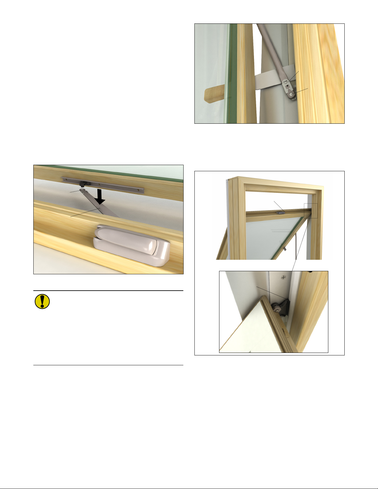
2. Detach the operator arm from the track by sliding
back the clip and then pushing the operator arm
down. See figure 4. Crank the arm back to the
frame.
Figure 4
CAUTION
To avoid damage to the sash and/or personal injury, the
awning sash must be fully supported at all times. Do
not lift sash past 60 degrees with the hinge arms
attached. Do not rack the hinges during removal, the
sash rail must remain parallel to the head jamb when
removing or installing the sash. Do not tip or rest the
sash on the corners.
3. While fully supporting the sash, detach the hinge
linkages from both sides of the sash by using a flat
head screwdriver to disengage the clip. Pry hinge
arm inward to release the arm from the hinge stud.
See figure 5.
Figure 5
4. Gently lower the sash until the shoe on both sides
of the sash are below the groove in the hinge track.
Remove sash from the frame by pulling it outward.
See figure 6.
Figure 6
5. To reinstall the sash, reverse the sash removal
procedures. Keep the sash shoes flat up against
the track just in front of the groove. Keeping the
sash stile parallel to the sill, slide the sash shoes
into the groove in the track. The sash should be
fully supported until both shoes are securely
engaged with the hinge track and the hinge arms
are placed onto the hinge studs and clips seated.
See figure 4, figure 5 and figure 6.
Detach clip
Operator arm
Clip
Hinge stud
Carefully lower top of sash
Groove in
hinge track

3
2019-07-29
19970160
Sash Limiter Installation
Ultimate Casement Field Applied Instruction
Install the Sash Limiter
1. Using a screwdriver, disconnect and remove the
frame bracket from the limiter arm. See figure 7.
Figure 7 Disconnect and remove frame bracket.
2. Referencing the chart and illustrations below,
obtain the correct location for the sash track
(dimension A) and frame bracket (dimension C).
Depending on the height of your window, you may
need to apply two tracks (dimension A and B for
the sash track, and dimension C and D for the
frame bracket). See figure 8, figure 9 and figure 10.
NOTE: Predrill all hole locations using a 3/32" or 7/64"
drill bit.
NOTE: For Awnings that require one sash limiter:
Apply on the exterior right hand side.
Figure 8 Casement sash shown.
Applies to Casement stile (A and B) and Awning bottom rail (B).
Figure 9 Clad frame (also applies to wood frame).
Applies to Casement jamb.
Ultimate Casement
Sash Track
Location
Frame Bracket
Location
Frame
Height
Dim
A
Dim
BDim C Dim D
11 1/2" -
23"
(292-584)
1"
(25) n/a 6 23/32"
(171) n/a
23 1/8" -
71 1/8"
(587-1807)
10"
(254) n/a 15 23/32"
(399) n/a
> 71 1/8"
(1807)
10"
(254)
10”
(254)
15 23/32"
(399)
15 23/32"
(399)
Ultimate Awning (see figure 8 and figure 10)
Sash Track
Location
Frame Bracket
Location
Frame Height Dim
A
Dim
B
Dim
CDim D
16" - 23 3/32"
(406-587) n/a 1"
(25) n/a 6 23/32"
(171)
23 1/8" - 72"
(587-1829) n/a 10"
(254) n/a 15 23/32"
(399)
Frame bracket
Limiter arm
Type of Unit Dim E
Replacement 1 5/32" (29)
Clad Full Frame 2 19/32" (66)
Wood Full Frame 1 1/2" (37)
3 7/8" (98)
1/2"
(13)
1/2"
(13)
3 7/8" (98)
11/16" (43)

4
2019-07-29
19970160
Sash Limiter Installation
Ultimate Casement Field Applied Instruction
Figure 10 Clad frame shown (also applies to wood frame).
Applies to Casement jamb and Awning sill.
3. Using the measurements from step 2, apply one
#8x11/16" pan head screw through the sash track
and into the stile. Slide the limiter arm into the track
and then apply the second screw. See figure 11.
Figure 11 Install the sash track and limiter arm.
NOTE: If installing the custodial sash limiter, secure
the sash track by using the tamper proof screws
provided.
4. Using the measurements obtained from step 2,
fasten the frame bracket using #8x11/16" screws
provided. See figure 12.
Figure 12 Fasten the frame bracket to the frame.
NOTE: For the custodial version, secure with tamper
proof screws.
5. Reinstall the sash by reversing the previous steps.
6. Attach the limiter arm to the frame bracket by
engaging the slider piece with the stud. See
figure 13.
Figure 13 Attach the limiter arm to the frame bracket.
NOTE: For the custodial version, apply the snap ring
to the stud.
11/16" (43)
Sash track
Limiter arm
Frame Bracket
Popular Household Hardware manuals by other brands

BLUM
BLUM SERVO-DRIVE uno Instruction leaflet

Lefroy Brooks
Lefroy Brooks M1-5310 Installation, operating, & maintenance instructions

Pressalit Care
Pressalit Care Indivo RK1010 User and maintenance guide

Gordon Ellis & CO
Gordon Ellis & CO ELEPHANT FEET 6070 quick start guide

TESA
TESA BNR 77775 Product information

Stratco
Stratco X-1 Steel Framing Design guide