Marvin GX97028 Instruction Manual

www.marvingroup.com 1 of 6 v1.2
Marvin Test Solutions, Inc
1770 Kettering
Irvine, California 92614 USA
T: +1 (949) 263-2222
F: +1 (949) 263-1203
www.marvintest.com
Installing a GX97028 Replacement Power Supply
This guide describes how to install a GX97028 replacement power supply into MTS GX7000/10,
GX7100/10, GX7200/10, GX7300/10 revision C or higher, GX7600/10 and GX7800 chassis. The
replacement power supply utilizes a 24-Pin ATX plug connector while the MTS backplane for
certain models utilize a 20-Pin ATX socket connector.
Relevant Information
The ATX power supply provided will have a 24-pin connector that will be plugged into the
backplane of the chassis models listed above. The ATX Power Supply Connector (labeled CN1)
depicted in Figure 1 will have pins one through three marked with raised bars on the connector
housing: one bar for pin 1, two bars for pin 2 and three bars for pin 3. On the reverse side of
this connector, you will see the latch and a green control line.
Figure 1: 24 Pin ATX Power Supply Connector (CN1 Front & Back)
Required Equipment
A Phillips and Torx-10 screw driver will be necessary for opening the chassis.
RTV silicone adhesive (DOW 3145 or equivalent) and nylon tie wraps will be necessary to secure
connectors and cables within the chassis.
It may be necessary to obtain a 2-way Internal Power Y splitter cable depending on the chassis
configuration. See step 4 of Installation Process for more details.
It is advised to have the proper ESD equipment during the entire process.

www.marvingroup.com 2 of 6 v1.2
Opening the Chassis
1. Turn-off and remove power from the chassis.
2. Remove the bumpers from the back of the chassis using the Torx-10 screw driver. Note
Figure 2 below. Also note that the bumpers are keyed and their locations should be
noted and retained for reinstallation.
3. Remove all screws from the two sides of the chassis using the Phillips screw driver.
Retain all removed hardware for reassembly. Note Figure 3 below.
4. Lift and remove the top shell from the chassis. The bottom shell can be left on as the
power supplies can be accessed from top.
On the backplane of your chassis, you will find two 20 or 24-pin backplane power connectors.
One such connector is depicted in Figure 4, below.
Figure 4: GX73xx Backplane Power Connector
Figure 2: Chassis Bumpers
Figure 3: Chassis Side Panel

www.marvingroup.com 3 of 6 v1.2
Removing the Power Supply
1. Disconnect the ATX plug connector(s) from the backplane. Note Figure 4 above.
2. Disconnect the PPC power supply connector(s) from bridge board(s). Note Figure 5
below.
3. Disconnect the power supply from all peripherals and remove any nylon tie wraps that
are used to secure the cables to the bottom panel of the chassis.
4. Remove the screws holding the power supply to the panel. Keep the screws and any
standoffs for later use.
Figure 5: GX7070 Backplane Bridge Connector

www.marvingroup.com 4 of 6 v1.2
Installation process
1. Plug the ATX Power Supply Connector (CN1) into the Chassis Backplane Power
Connector (J1). There should be two connections on the backplane for each appropriate
power supply. Pin 1 of the Power Supply Connector CN1 should plug into Pin 1 of the
Backplane Power Connector. The two connector’s pins are keyed so if you are having
trouble making the connection, check to see if you have the pins lined up correctly.
2. Above in Table 1 identify the chassis model to which the power supply is being replaced
and check if CN2 needs to be connected. If so follow similar steps to connect CN2 to the
backplane except CN2 will be connected to J2.
3. If the connectors have a different number of pins, the latches will be offset and the
connector could vibrate loose. See Figure 4 below. It is necessary to apply RTV on the
seam where the two connectors attach to secure the connection.
Power Supply Connectors
Chassis
CN1
CN2
CN3
CN4
Gx700x
ATX Connector
on Backplane
NC
Both
Bridges
DVD/CD
Drive, HDD
Gx701x
ATX Connector
on Backplane
NC
Both
Bridges
NC
Gx710x
ATX Connector
on Backplane
NC
DVD/CD
Drive
HDD
Gx711x
ATX Connector
on Backplane
NC
NC
NC
Gx720x
ATX Connector
on Backplane
ATX
Connector on
Backplane
DVD/CD
Drive
HDD
Gx721x
ATX Connector
on Backplane
ATX
Connector on
Backplane
NC
NC
Gx7300 C or higher
ATX Connector
on Backplane
ATX
Connector on
Backplane
Both
Bridges
DVD/CD
Drive, HDD,
RTM
Gx7310 C or higher
ATX Connector
on Backplane
ATX
Connector on
Backplane
Both
Bridges
NC
Gx7600
ATX Connector
on Backplane
NC
Bridge
DVD/CD
Drive, HDD
Gx7610
ATX Connector
on Backplane
NC
Bridge
NC
GX7800
ATX Connector
on Backplane
NC
NC
NC
Table 1: Chassis and connectors with Power Supply Connectors

www.marvingroup.com 5 of 6 v1.2
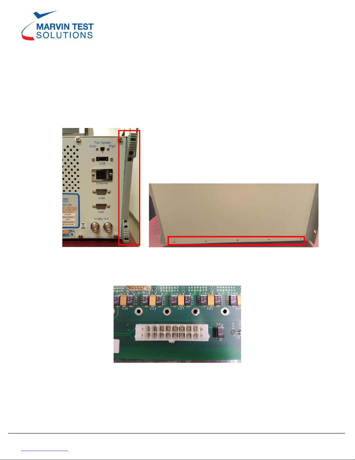
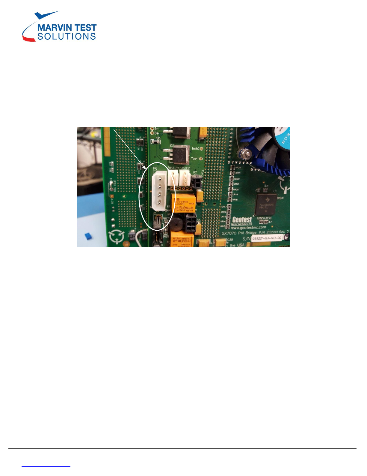
4. Connect CN3 of the Power Supply to P6 Connector on the bridge or to the connector
specified in Table 1 above. The P6 connector on the backplane is shown in Figure 3
above. It is necessary to apply RTV adhesive on the seam where the two connectors
attach to secure the connection.
5. With a Master configuration as in a GX7x0x not a GX7x1x, CN4 must be connected to a
splitter to power peripherals as defined by Table 1. (Note: A GX7x1x chassis does not
have any peripherals so it will not need a splitter)
a. If the configuration includes a GX7935/36/37 controller then there are 3
powered peripherals. They are the Rear Transition Module (RTM), the DVD/CD
drive and the hard drive. One power supply needs to power one peripheral and
the other power supply needs to power the other two peripherals. It is not
necessary to have any one power supply powering any specific peripheral.
b. If another master configuration, i.e. GX7927/30/32/34, exists there will be only 2
powered peripherals. They are the DVD/CD drive and the hard drive. The
peripherals can be split between the two power supplies and a splitter will not
be needed.
6. Tie down the cables with nylon tie wraps to the chassis lower frame. Make sure to
organize the cables such that the cables are not loose within the chassis or does not
obstruct the fans.
7. Mount the power supply to side wall with the screws that were removed from the
previous power supply, using any existing spacers as necessary.
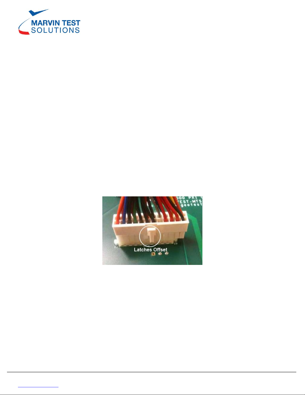
Figure 6: Latch is offset; RTV must be applied to secure the connector

www.marvingroup.com 6 of 6 v1.2
Closing the Chassis
1. Place the top shell onto the chassis. Slide the lip under the front making sure to keep
alignment with the side panel and bumper screw holes.
2. Screw in the 10 side panel screws onto the chassis (5 on each side) using the Phillips
screw driver. Note Figure 3 above.
3. Screw in the 2 bumpers on the back of the chassis using the Torx-10 screw driver. Note
Figure 2 above. Observe the bumper keying to align the bumper correctly.
Testing the Chassis
1. With the chassis switch in the off position, install the AC power cord.
2. Apply power to the chassis and verify proper POST and OS booting. If the GX7xxx
chassis is a slave configuration, power must be applied to the chassis before powering
up the host PC.
3. Launch the GxChassis Panel and initialize it. Go to the “Advance”tab and verify that the
backplane voltages are within specification.
Table of contents