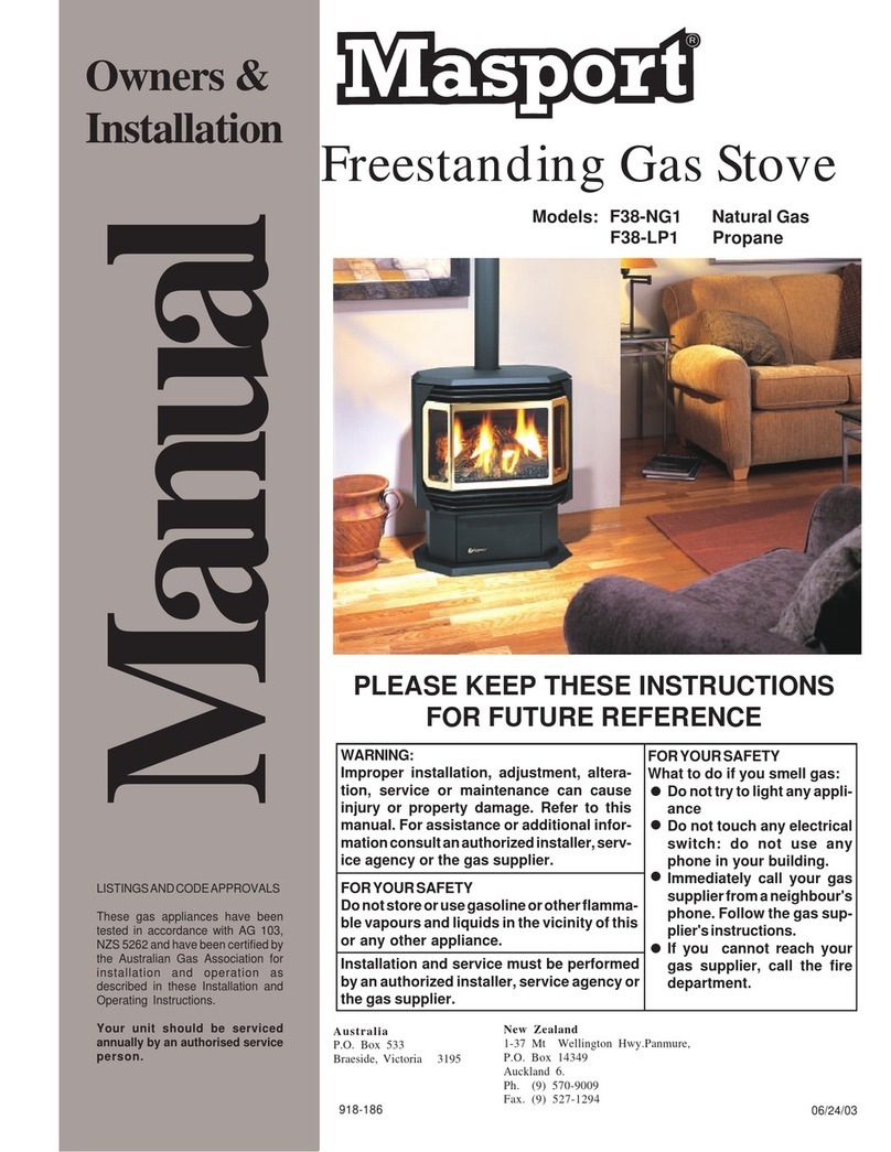
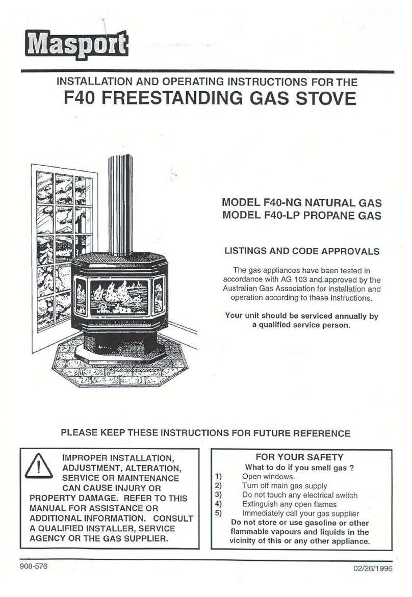
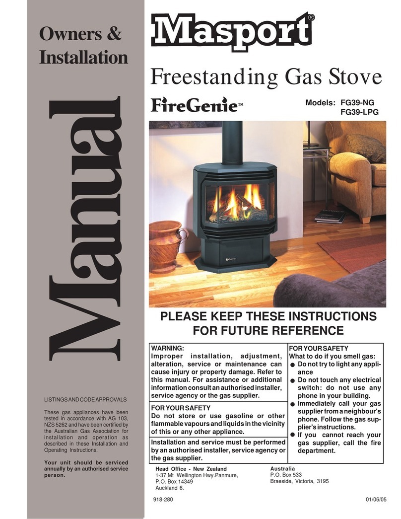
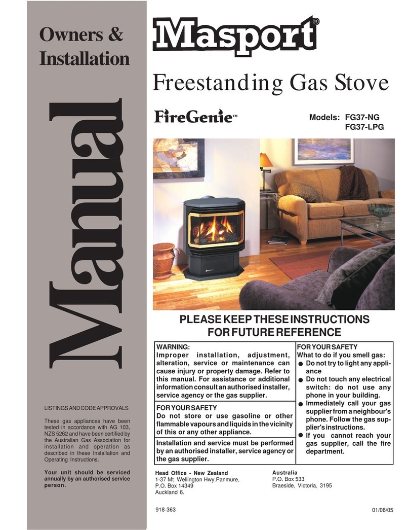
Masport Geneva F39-NG Quick start guide

01/20/04
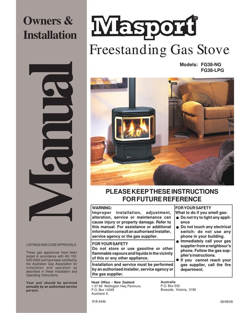
Freestanding Gas Stove
FORYOURSAFETY
What to do if you smell gas:
Donottrytolightanyappli-
ance
Do not touch any electrical
switch: do not use any
phone in your building.
Immediately call your gas
supplierfromaneighbour's
phone. Follow the gas sup-
plier'sinstructions.
If you cannot reach your
gas supplier, call the fire
department.
WARNING:
Improper installation, adjustment, altera-
tion, service or maintenance can cause
injury or property damage. Refer to this
manual. For assistance or additional infor-
mationconsultanauthorizedinstaller,serv-
ice agency or the gas supplier.
FORYOURSAFETY
Donotstoreorusegasolineorotherflamma-
blevapoursand liquids in thevicinityof this
or any other appliance.
Installation and service must be performed
byanauthorized installer, serviceagencyor
the gas supplier.
PLEASE KEEP THESE INSTRUCTIONS
FOR FUTURE REFERENCE
Owners &
Installation
Manual
LISTINGSANDCODEAPPROVALS
These gas appliances have been
tested in accordance with AG 103,
NZS5262andhavebeencertifiedby
the Australian Gas Association for
installation and operation as
described in these Installation and
Operating Instructions.
Your unit should be serviced
annually by an authorised service
person.
918-082b
Models: F39-NG
F39-LPG
Australia
P.O. Box 533
Braeside, Victoria 3195
New Zealand
1-37 Mt Wellington Hwy.Panmure,
P.O. Box 14349
Auckland 6.
Geneva

2Masport F39 Room Sealed Freestanding Gas Fire
To the New Owner:
Congratulations! You are the owner of a state-of-the-art Masport Room Sealed Gas Fire by FPI Fireplace
ProductsInternationalLtd.TheMasportGasSeriesofhandcraftedapplianceshasbeendesignedtoprovide
you with all the warmth and charm of a woodstove, at the flick of a switch. The models F39-NG, and
F39-LPGofthisserieshasbeenapprovedbyAGAforbothsafetyandefficiency.Asitalsobearsourownmark,
it promises to provide you with economy, comfort and security for many trouble free years to follow. Please
takeamomentnowtoacquaintyourselfwiththeseinstructionsandthemanyfeaturesofyourMasportRoom
Sealed Freestanding Gas Fire.
F39-NG & F39-LPG
UNIT SPECIFICATIONS

Masport F39 Room Sealed Freestanding Gas Fire 3
TABLE OF CONTENTS
Page Page
Operating Instructions
Operating Instructions....................................................17
Lighting Procedure .........................................................17
Shutdown Procedure......................................................17
First Fire..........................................................................17
Convection Fan Operation .............................................17
Adjusting Flame Height..................................................17
Copy of Lighting Plate Instructions ................................18
Normal Operating Sounds of Gas Appliances .............18
Maintenance
Maintenance Instructions ...............................................19
General Flue Maintenance .............................................19
Gold Plated Doors..........................................................19
Log Replacement...........................................................20
Door Gasket ...................................................................20
Latch Adjustment............................................................20
Glass Replacement .......................................................20
Fan Maintenance ............................................................21
Removing Valve..............................................................22
Firebox Paint...................................................................22
Replacement Parts List .................................................23
Warranty
Warranty..........................................................................27
Safety Label
Safety Labels ................................................................... 4
Installation
Important Message ..........................................................5
Specifications ...................................................................5
Before You Start................................................................5
General Safety Information...............................................5
Installation Checklist ........................................................6
Clearances to Combustibles...........................................6
Locating Your Masport Gas Fire ......................................6
Combustion and Ventilation Air .......................................6
Louvre Installation ............................................................7
Flueing..............................................................................7
Installation Precautions ...................................................7
Safety Precautions for the Installer ..................................7
Exterior Flue Termination Locations ................................8
Fluing Arrangements - Horizontal
Terminations: All Systems ........................................9
Fluing Arrangements - Vertical Terminations..................9
- Straight Vertical .......................................................9
- Offset Vertical ..........................................................9
Flue Restrictor Position....................................................9
Gas Connection .............................................................10
Pressure Testing............................................................10
Valve Description............................................................10
System Data Chart .........................................................11
Aeration Adjustment .......................................................11
Conversion from NG to LPG ..........................................12
Conversion to Lower BTU ..............................................13
Log Installation ...............................................................13
Front Door Installation....................................................15
Wall Thermostat (optional).............................................15
Remote Control (optional) .............................................15
Final Check.....................................................................15
Wiring Diagram ..............................................................16

4Masport F39 Room Sealed Freestanding Gas Fire
SAFETY LABEL
This is a copy of the label that accompanies
eachMASPORTF39RoomSealed Freestand-
ing Gas Stove. We have printed a copy of the
contents here for your review. The data plat is
locatedon the inside of the drop down pedestal
door.
NOTE: Masport units are constantly being im-
proved. Check the label on the unit and if there
isadifference,thelabelontheunitisthecorrect
one.
(AustraliaOnly)

Masport F39 Room Sealed Freestanding Gas Fire 5
IMPORTANT:
SAVE THESE
INSTRUCTIONS
TheMASPORTRoomSealedFreestandingGas
Fire must be installed in accordance AG601
and NZS 5261 and with these instructions.
Carefullyreadalltheinstructionsinthismanual
first.Consultthebuildingauthorityhavingjuris-
diction to determine the need for a permit prior
to starting the installation.
Note: Failure to follow the instructions
could cause a malfunction of the
heater which could result in death,
serious bodily injury, and/or prop-
erty damage. Failure to follow
these instructions may also void
your fire insurance and/or war-
ranty.
Note: These instructions take prece-
dence over Simpson Dura-Flue in-
structions.
SPECIFICATIONS
Fuels: F39-NG is approved for use with NG.
F39-LPG is approved for use with liq-
uefied petroleum gases (LPG).
Electrical: 240V A.C. system.
Circulation Fan: Variable speed, 125/75.
Log Sets: Ceramic fibre, 7 per set.
Flue System: Coaxial (6-5/8" outer / 4" inner
liner) rigid flue and termination cap.
BEFORE YOU START
Safeinstallationandoperationofthisappliance
requires common sense, however, we are
required by the Canadian Safety Standards
and ANSI Standards to make you aware of the
following:
INSTALLATION
ING,ETC. ITISIMPERATIVETHAT
THECONTROLCOMPARTMENT,
BURNERSANDCIRCULATINGAIR
PASSAGEWAYS OF THE APPLI-
ANCEBEKEPTCLEAN.
DUE TO HIGH TEMPERATURES,
THEAPPLIANCESHOULDBELO-
CATED OUT OF TRAFFIC AND
AWAY FROM FURNITURE AND
DRAPERIES.
WARNING:FAILURETOINSTALL
THIS APPLIANCE CORRECTLY
WILLVOIDYOURWARRANTYAND
MAY CAUSE A SERIOUS HOUSE
FIRE.
CHILDRENANDADULTSSHOULD
BE ALERTED TO THE HAZARDS
OF HIGH SURFACE TEMPERA-
TURES, ESPECIALLY THE FIRE-
PLACE GLASS, AND SHOULD
STAY AWAY TO AVOID BURNS
ORCLOTHINGIGNITION.
YOUNG CHILDREN SHOULD BE
CAREFULLY SUPERVISEDWHEN
THEYAREINTHESAMEROOMAS
THEAPPLIANCE.
CLOTHINGOROTHERFLAMMA-
BLEMATERIALSHOULDNOTBE
PLACEDONORNEARTHEAPPLI-
ANCE.
INSTALLATION AND REPAIRS
SHOULDBEDONEBYANAUTHOR-
IZEDSERVICEPERSON.THISAP-
PLIANCESHOULDBEINSTALLED,
REPAIRED,INSPECTEDBEFORE
USE AND AT LEAST ANNUALLY
BYANAUTHORIZEDSERVICEPER-
SON. MORE FREQUENT CLEAN-
ING MAY BE REQUIRED DUE TO
EXCESSIVELINTFROMCARPET-
page 7. This unit is approved for manufac-
tured home installations, see page 9 for the
required flue arrangements. If installed into
a manufactured home the unit must be
bolted down to the floor.
4) This appliance is Listed for bedroom instal-
lations when used with a Listed Millivolt
Thermostat. Some areas may have further
requirements, check local codes before
installation.
5) This appliance is Listed for Alcove installa-
tions,maintainminimumAlcove clearances
asfollows, minimumwidthof48"(1219mm),
a maximum depth of 36" (914mm), and
minimum ceiling height of 66" (1676mm).
6) We recommend that you plan your installa-
tion on paper using exact measurements
for clearances and floor protection before
actually installing this appliance. Have an
authorized building inspector review your
plans before installation.
GENERAL SAFETY
INFORMATION
1) The appliance shall be installed in accord-
ance with the manufacturer's installation
instructions,localgasfittingregulations,mu-
nicipal building codes, water supply regu-
lations, electrical wiring regulations, with
AG 601 (AGA gas installation code) NZS
5261 (New Zealand)
2) Installation and repair should be done
ONLY by an authorised person.
3) DONOTCONNECTTOMASONARYFLUE.
4) This appliance must be connected to
the specified flue and termination cap
to the outside of the building enve-
lope. Never flue to another room or
inside a building. Make sure that the
flue is fitted as per Flueing instruc-
tions.
5) Inspect the flueing system annually for
blockage and any signs of deterioration.
6) Flueing terminals shall not be recessed into
a wall or siding.
7) Any safety glass removed for servicing
must be replaced prior to operating the
appliance.
8) To prevent injury, do not allow anyone who
is unfamiliar with the operation to use the
fireplace.
9) Wear gloves and safety glasses for protec-
tion while doing required maintenance.
1) Provide adequate clearances for servicing,
proper operation and around the air open-
ings into the combustion chamber.
2) The appliance may be installed on a flat,
solid, continuous surface (e.g. wood, met-
al,concrete). This maybe the floor, or it can
be raised up on a platform to enhance its
visual impact. The appliance may be in-
stalled on carpeting, tile, wood flooring or
other combustible material, because the
appliance's metal pedestal base extends
the full width and depth of the appliance.
The Masport Room Sealed Freestanding
Gas Fire can be installed in a wide variety
of ways and will fit nearly any room layout.
It may be installed in a recessed position,
framed out into the room, or across a cor-
ner.
3) The Masport Room Sealed Freestanding
Gas Fire is approved for alcove installa-
tions, which meet the clearances listed on
6Masport F39 Room Sealed Freestanding Gas Fire
INSTALLATION
2) If required, adjusting the primary air to
ensurethattheflamedoesnotcarbon.First
allow the unit to burn for 15-20 min. to
stabilize.
CAUTION: Any alteration to the product
that causes sooting or carboning that
results in damage is not the responsibil-
ity of the manufacturer.
CLEARANCES TO
COMBUSTIBLES
TheclearanceslistedareMINIMUM distances.
Measure the clearance to both the appliance
and the chimney connector. The farthest
distance is correct if the two clearances
do not coincide.
Forexample, iftheapplianceis setasindicated
in one of the figures but the connector is too
close, move the stove until the correct clear-
ance to the connector is obtained.
This appliance may be installed only with the
clearances as shown in the situations pic-
tured. Do not combine clearances from
one type of installation with another in
order to achieve closer clearances.
Thisunitcanbeinstalledonasolidcombustible
surface like a wood floor. This unit can also be
installeddirectlyon carpeting or vinyl when the
bottom pedestal cover plate (provided with
unit) is installed.
Use the minimum clearances shown in the
diagrams below:
F39-NG & F39-LPG Clearances
A Side Wall to Unit 190mm
B Back Wall to Unit 150mm
E Side Wall to Unit 50mm
10)Be aware of electrical wiring locations in
walls and ceilings when cutting holes for
termination.
11)Under no circumstances should this appli-
ance be modified. Parts that have to be
removed for servicing should be replaced
prior to operating this appliance.
12)Installationandanyrepairstothisappliance
should be done by an authorised service
person. An authorised service person
should be called to inspect this appliance
annually. Make it a practice to have all of
your gas appliances checked annually.
13)Do not slam shut or strike the glass door.
14)Under no circumstances should any solid
fuels (wood, paper, cardboard, coal, etc.)
be used in this appliance.
15)The appliance area must be kept clear and
free of combustible materials, (gases and
other flammable vapours and liquids).
INSTALLATION
CHECKLIST
1) Check Clearances to Combustibles (pages
6and 7), location ofunit (page 6) and fluing
requirements (pages 7 to 9).
2) Install Louvers, page 7.
3) Make gas connections, page 10. Test the
pilot. Must be as per diagram, page 19.
4) If necessary, convert to LPG (page 12) or
convert to lower Btu rating (page 13).
5) Test Gas Pressure, page 10.
6) Install log set, see page 13.
7) Install Front Door Front, page 15.
8) InstalloptionalRemoteControl,orWallTher-
mostat, page 15.
9) Final check, page 15.
Before leaving this unit with the customer, the
installer must ensure that the appliance is firing
correctly and operation fully explained to
customer.
This includes:
1) Clockingtheappliancetoensurethecorrect
firing rate (rate noted on label) after burning
appliance for 15 minutes.
F39-NG & F39-LPG
Reference Dimensions
C Back Wall to Flue Centerline 11" / 280 mm
D Side Wall to Flue Centerline 521mm
F Side Wall to Flue Centerline 280 mm
Minimum ceiling
height is 914 mm
from top of unit.
LOCATING YOUR
MASPORT GAS FIRE
When selecting a location for your stove,
ensure that the clearances listed above are
met as well as ensuring that there is adequate
accessibility for servicing and proper opera-
tion.
A) Cross Corner
B) RoomDivider
C) Island
D) Flat on Wall
E) Flat on Wall Corner
F) Flush with Wall/ Alcove
ForFlueTerminationrequirements,seepage8.
COMBUSTION AND
VENTILATION AIR
Thecombustionairfromthisapplianceisdrawn
fromoutsidethebuildingthroughtheouterflue.
Extra provision for combustion air inside
the room is not required.

Masport F39 Room Sealed Freestanding Gas Fire 7
LOUVRE
INSTALLATION
1) Attachthetop&bottomlouvrestothe
side stove panel using 2 screws per
side.
INSTALLATION
FLUEING
INTRODUCTION
TheDVFireHorizontalFlueKitandtheSimpson
Dura-FlueRoom SealedSystemModelDV-GS
fluingsystems, in combinationwiththeMasport
RoomSealed FreestandingGasFire, F39-NG,
and F39-LPG, have been tested and listed as
direct flue heater systems by AGA.
Theseunitsusethe"balanced flue" technology
Co-Axial system. The inner liner flues products
of combustion to the outside while the outer
pipe draws outside combustion air into the
combustion chamber thereby eliminating the
needtouseheatedroomairforcombustionand
losing warm room air up the chimney.
Note: These flue pipes must not be con-
nected to any other appliance.
The gas appliance and flue system must be
flued directly to the outside of the building, and
never be attached to a chimney serving a
separate solid fuel or gas burning appliance.
Eachdirectfluegasappliancemustuseit'sown
separate flue system. Common flue systems
are prohibited.
IMPORTANT
Read all instructions carefully before starting
the installation. Failure to follow these instruc-
tions may create a fire or other safety hazard,
and will void the warranty. Be sure to check the
fluing and clearance to combustible require-
ments.Consultyourlocalbuildingcodesbefore
beginning installation.
The location of the termination cap must con-
form to the requirements in the Exterior Flue
Terminal Locations diagram on page 8.
Refer to the Masport Flue Kit in-
structions supplied with each kit.
INSTALLATION
PRECAUTIONS
These fluing systems are engineered products
that have been designed and tested for use
with the F39-NG, and F39-LPG. The warranty
will be voided and serious fire, health or other
safety hazards may result from any of the
following actions:
1) Installation of any damaged Room Sealed
component
2) Unauthorized modification of the Room
Sealed System
3) Installationofanycomponentpartnotman-
ufactured or approved by Masport.
4) Installation other than as instructed by
Masport.
Warning: Alwaysmaintainrequired
clearances (air spaces) to nearby
combustibles to prevent a fire haz-
ard.Do not fill airspaceswithinsu-
lation.
Besuretocheck the flue termination clearance
requirements from decks, windows, soffits,
gas regulators, air supply inlets and public
walkways as specified in the Exterior Flue
Terminal Locations on page 8 and in your local
building codes.
The gas appliance and flue system must
be flueed directly to the outside of the
building, and never be attached to a chim-
ney serving a separate solid fuel or gas-
burning appliance. Each direct flue gas ap-
pliance must use it's own separate flue sys-
tem. Common flue systems are prohibited.
SAFETY
PRECAUTIONS FOR
THE INSTALLER
1) Wear gloves and safety glasses for pro-
tection.
2) Exercise extreme caution when using
ladders or on roof tops.
3) Be aware of electrical wiring locations in
walls and ceilings.

8Masport F39 Room Sealed Freestanding Gas Fire
INSTALLATION
EXTERIOR FLUE TERMINATION LOCATIONS
Minimum clearances required for balanced flue terminals or
the flue terminals of outdoor appliances
according to AG 601 (AGA gas installation code) or NZS 5261 (New Zealand)
For vertical termination heights refer to AG 601 or NZS 5261.
Minimum
Clearance (mm)
a Below eaves, balconies or other projections:
- Appliances up to 50 MJ/h input 300
- Appliances over 50 MJ/h input 500
b From the ground or above a balcony 300
c From a return wall or external corner 500
d From a gas meter (M) 1000
e From an electricity meter or fuse box (P) 500
f From a drain or soil pipe 150
g Horizontal from any building structure (unless appliance is approved
for closer installation) or obstruction facing a terminal 500
h From any other flue terminal, cowl or combustion air intake 500
j Horizontally from an openable window, door, or non-mechanical air inlet, or
any other opening into a building, with the exception of sub-floor ventilation
(see also Note (I)):
- Appliances up to 150 MJ/h input 500
- Appliances over 150 MJ/h input 1500
k Vertically below an openable window, door, or non-mechanical air inlet,
or any other opening into a building, with the exception of sub-floor ventilation
(see also Note (I)): see table below
Clearance 'k' in mm
Space Heaters All Other Appliances
Up to 50 MJ/h Up to 50 MJ/h input Over 50 MJ/h input Over 150 MJ/h input
input to 150 MJ/h input
150 500 1000 1500
NOTES:
(I) For mechanical air inlets, including spa blowers, the clearance 'j' and 'k' shall be 1500 mm in all cases.
(II) All distances shall be measured vertically or horizontally along the wall to a point in line with the nearest
par to of the terminal.
(III) Prohibited area below electricity meter or fuse box extends to ground level.
(IV)A flue terminal of this type shall not be located under a roofed area unless the roofed area is fully open on
at least two sides and a free flow of air at the appliance is achieved.

Masport F39 Room Sealed Freestanding Gas Fire 9
INSTALLATION
FLUEING ARRANGEMENTS
Vertical Terminations
Residential Manufactured and Mobile Homes
The shaded area in the diagram below shows all allowable
combinations of straight vertical and offset to vertical runs
with vertical terminations. Maximum two 45oelbows.
If the flue is ENCLOSED in a chase (min. size 10" (255mm) x 10"
(255mm)) maintain a 40mm" clearance to combustibles.
May be installed in Manufactured (Mobile) Homes after first sale.
Horizontal Terminations for All Flueing Systems
The shaded areas in the diagram below show all allowable
combinations of vertical runs with horizontal terminations.
Maximum one 90Oelbow (two 45o elbows equal one 90oelbow).
LPG and NG:
Residential, Manufactured and Mobile Homes
Installations
The fluing arrangements shown below, have a min. of 75% (flue loss)
efficiency with Fan Off, as required for manufactured homes. (Actual
efficiency may be as high as 85%)
May be installed in Manufactured (Mobile) Homes after first sale.
FlueRestrictorPosition
To set the Flue restriction as indicated in the diagram, simply loosen the
screws and push the flue restrictor plate to the correct position. Tighten
the screws.
Flue Restrictor setting at
40 Mj/h Flue Restrictor setting at
31 Mj/h

10 Masport F39 Room Sealed Freestanding Gas Fire
PRESSURE TESTING
The manifold pressure is controlled by a regu-
lator built into the gas control, and should be
checked at the pressure test point.
Note: To properly check gas pressure,
both inlet and manifold pressures
should be checked using the valve
pressure ports on the valve.
1) Makesurethevalveisinthe"OFF"position.
2) Loosen the "IN" and/or "OUT" pressure
tap(s), turning counterclockwise with a 1/
8" wide flat screwdriver.
3) Attach manometer to "IN" and/or "OUT"
pressure tap(s) using a 5/16" ID hose.
4) Light the pilot and turn the valve to "ON"
position. Read manometer.
5) The pressure check should be carried out
with the unit burning and the setting should
be within the limits specified on the safety
label.
6) When finished reading manometer, turn off
the gas valve, disconnect the hose and
tighten the screw (clockwise) with a 1/8"
flat screwdriver. Note: Screw should be
snug, but do not over tighten.
GAS CONNECTION
The gas connection is a 3/8" NPT 90oelbow.
The gas line can be rigid pipe or to make
installation easier, use a listed flexible connec-
tor and/or copper tubing if allowed by local
codes. Since some municipalities have addi-
tional local codes it is always best to consult
with your local authorities.
When using copper or flex connectors use
only approved fittings. Always provide a union
sothat gas linescanbeeasilydisconnected for
burner and/or valve servicing. Flare nuts for
copper lines and flex connectors are usually
considered to meet this requirement.
Important: Always check for gas leaks
with a soap and water solution or gas
leak detector. Do not use open flame for
leak testing.
Note: Prior to any pressure testing of
the gas supply piping system that
exceeds test pressures of 3.45
kPa, this appliance must be dis-
connected from the piping sys-
tem. If test pressures equal to or
less than 3.45 kPa are used then
this appliance must be isolated
from the piping system by closing
its individual manual shut-off valve
during the testing.
INSTALLATION
Valve Description
1) Gas cock knob
2) Manual high/low adjustment
3) PilotAdjustment
4) Thermocouple Connection
5) Main Operator
6) Outlet Pressure Tap (Manifold
Pressure)
7) Inlet Pressure Tap (Supply
Pressure)
8) PilotOutlet
9) Main Gas Outlet
10)Flange Securing Screw Holes
11)Alternative TC Connection Point
12)Thermoelectric Unit
13)Additional Valve Mounting Hole

Masport F39 Room Sealed Freestanding Gas Fire 11
Burner Inlet Orifice Sizes:
NG LPG
Burner #32 #50
2.95mm 1.78mm
Max. Input NG 40 Mj/h
LPG 38Mj/h
Min. Input NG 20Mj/h
LPG 19Mj/h
Supply Pressure
NG min. 1.13 kPa
LPG min.2.75kPa
Manifold Pressure
NG .94kPa
LPG 2.55kPa
Electrical: 240 V. 1.13A 60Hz.
Circulation: 2 speed fan, 125/75 CFM.
Log Set: Ceramic fiber, 7 per set.
System Data
F39 Converted to 31mj
Burner Inlet Orifice Sizes:
NG #37 2.65mm
LPG #52 1.6mm
Max. Input - NG/LPG
31Mj/h
Min. Input - NG/LPG
16Mj/h
Supply Pressure
NG min. 1.13 kPa
LPG min.2.75kPa
Manifold Pressure
NG .89kPa
LPG 2.55kPa
Electrical: 240 V. 1.13A 60Hz.
Circulation:Variablespeedfan,125/75CFM.
Log Set: Ceramic fiber, 7 per set.
System Data
F39 with 40mj
INSTALLATION
AERATION
ADJUSTMENT
The burner aeration is factory set but may need
adjusting due to either the local gas supply or
altitude.
F39 with 40mj
F39-NG NG: Fullopen
F39-LPG LPG: Fullopen
F39 with 31mj
F39-NG NG 6mmopen
F39-LPG LPG 10mmopen
The aeration adjustment gears are located on
the right side of the burner box and can be
accessed from the side or from the front when
the louvres are removed.
To adjust the aeration: use the allen key to turn
theturninggear which will adjust theairshutter.
Open the air shutter for a blue flame or close it
for a yellower flame. This adjustment is per-
formed by an authorized installer. The factory
setting should be sufficient for most installa-
tions.
Caution: Carbon will be produced if the
air shutter is closed too much.
Note: Any damage due to carboning re-
sulting from improperly setting
the aeration controls is NOT cov-
ered under warranty.
Clockwise to open,
counter-clockwise to close.

12 Masport F39 Room Sealed Freestanding Gas Fire
INSTALLATION
InstallerNotice:
These instructions must be left
with the appliance.
Burner Orifice
CONVERSION FROM NG TO LPG
THIS CONVERSION MUST BE DONE BY AN AUTHORIZED GAS FITTER
IF IN DOUBT DO NOT DO THIS CONVERSION !!
Conversion Kit #730-969 Contains:
Qty. Part # Description
1 910-018 SIT Conversion Kit-
50% Turndown LPG
1 910-037 LPG Injector (Pilot Orifice)
1 904-641 Burner Orifice #50
1 908-528 Red"LPG"label
1 908-255 Label "Converted to LPG"
1 918-032 Instruction Sheet
1) Shut off the gas supply.
2) Open the front door and carefully remove
the logs and lava rock.
3) Remove burner. See diagram below.
Pilot assembly is now accessible for steps
4) to 9).
Note: Use a magnetic type screwdriver if pos-
sible.
4) Remove and discard the 3 pressure reg-
ulator mounting screws (A), pressure
regulator tower (B) and diaphragm (C).
5) Insure that the rubber gasket (D) is prop-
erly positioned and install the new HI/LO
pressureregulatorassembly tothevalve
using the new screws (E) supplied with
the kit. Tighten screws securely.
6) Pull off the pilot cap to expose the pilot
orifice.
7) Unscrew the pilot orifice with the allen key
and replace with the LPG pilot orifice in the
kit.
8) Remove burner orifice with a 1/2" spanner
anddiscard.Useaspannertoholdontothe
elbow behind the orifice.
9) Reinstall new burner orifice LPG stamped
#50 and tighten.
10)Reverse steps 3) to 2).
11)Attach the Conversion label "This unit has
been converted to LPG" on top of the data
badge.
12)Replace yellow "NG" label with red "LPG"
label
13)Check for gas leaks.
14)Check inlet and outlet pressures.
15)Check operation of flame control.
16)Check for proper flame appearance and
glow on logs.

Masport F39 Room Sealed Freestanding Gas Fire 13
LOG SET
INSTALLATION
Read the instructions below carefully
and refer to the diagrams. If logs are
broken do not use the unit until they are
replaced. Broken logs can interfere with
the pilot operation.
The gas log kit contains the following:
a) 02-65 Rear Log 902-267
b) 02-56 Middle Left Log 902-230
c) 02-44 Front Left Log 902-228
d) 02-46 Left Top Log 902-231
e) 02-45 Front Right Log 902-229
f) 02-47 Center Log 902-232
g) 02-48 MiddleRightLog 902-226
h) Embers 902-151
i) Lava 902-154
Note: Install Optional Brick Panels prior
to installing logs.
Embers Embers
The "02" refer numbers (i.e. 02-65) are
molded into the rear of each log.
1) Carefully remove the logs from the box and
unwrap them. The logs are fragile, handle
with care - do not force into position.
2) Sprinkle the embers on the left and right
sides of the firebox base.
INSTALLATION
CONVERSION TO LOWER BTU RATING
THIS CONVERSION MUST BE DONE BY AN AUTHORIZED
GAS FITTER IF IN DOUBT DO NOT DO THIS CONVERSION
!!
NG Conversion Kit 730-920
Contains:
Qty. Part # Description
1 904-240 Burner Orifice #37 (NG)
1 918-034 Decal "Converted to 30,000 Btu"
1 918-033 Instruction Sheet
LPG Conversion Kit 730-922
Contains:
Qty. Part # Description
1 904-390 Burner Orifice #52 (LPG)
1 918-034 Decal "Converted to 30,000 Btu"
1 918-033 Instruction Sheet
Additional Piece (pkg. with unit:
1 Log Bracket Restrictor
1) Shut off the gas supply.
2) Open the front door. Carefully remove the
logs and lava rock.
3) Remove burner. See diagram below.
Burner Orifice
4) Unscrew the 2 Rear
Log Pins and move
to the front hole po-
sition.
5) Remove Rear Log
Bracketandslidethe
Log Bracket Re-
strictor between the
Position the Log Bracket Restrictor between
the Rear Log Bracket and the burner.
6) Remove burner orifice with a 1/2" spanner
and discard.
7) Reinstall new burner orifice (NG stamped
#37 or LPG stamped #52) and tighten.
8) Reverse steps 3) and 2).
9) AdjustFluerestrictorsetting:TosettheFlue
restriction as indicated in the diagram, sim-
ply loosen the screws and push the flue
restrictorplatetothecorrect position. Tight-
en the screws.
Unit Btu/h Restrictor Opening
F39 40Mj/h A 45mm
31Mj/h B 35mm
Note: Use a
magnetic type
screwdriver if
possible.
Rear Log Bracket and the burner, secure
with the 2 screws.
Flue Restrictor
setting at High Btu/h Flue Restrictor
setting at Low Btu/h
10)Attach the label "This unit has been con-
verted to..." on top of the data badge over
the higher Btu information.
11)Check for gas leaks.
12)Check inlet and outlet pressures.
13)Checkoperationofflamecontrol. Check for
proper flame appearance and glow on logs.

14 Masport F39 Room Sealed Freestanding Gas Fire
Notch
E)02-45
Bracket
A)02-65
The bottom right edge of Log G)02-48 must
sit snugly against the bracket
Side View
G)02-48
E)02-45
F)02-47
11)Position notch in Front Right Log G)02-48
on Log F)02-47 and push the bottom right
edge against the bracket on the burner
tray.
G)02-48
12)Test fire to ensure proper light off (make
sure flame flows smoothly from one end of
burner to the other. If there is any flame
hesitation, check that area for any block-
age of the burner port.
F)02-47
E)02-45
A)02-65
G)02-48
D)02-46
B)02-56
C)02-44
Cutout
Pin
D)02-46
B)02-56
A)02-65
7) Place the Left Top Log D)02-46 on the pin
on Log B)02-56 and on top of the cutout on
Log A)02-65.
E)02-45
C)02-44
8) Place Front Right Log E)02-45 on the two
pins as shown.
9) Place thelavarockintheareabetweenthe
left and right logs, leaving a space in the
middle for log (F) 02-47.
CutoutNotch
F)02-47
E)02-45
A)02-65
10)Placethe notch in Center LogF)02-47 over
Log E)02-45 and across the cutout on Log
A)02-65.
C)02-44
Pins on Rear Log Support
A)02-65
B)02-56
3) Place Rear Log A)02-65 on the two pins on
the rear log support.
4) Place the Middle Left Log B)02-56 on the
two pins as shown.
5) Sprinkle some lava rock just in front of B)
02-56 on the burner holes.
lava rock
B)02-56
6) Place Front Left Log C)02-44 onto the 2
front pins as shown.
INSTALLATION

Masport F39 Room Sealed Freestanding Gas Fire 15
OPTIONAL WALL
THERMOSTAT
A wall thermostat may be installed if desired.
Connect the wires as per the wiring diagrams.
Note that the wires are connected to the "TH"
on the gas valve. Use table below to determine
the maximum wire length:
CAUTION
Do not connect the millivolt
wall thermostat wires
to the 240V wires.
OPTIONAL REMOTE
CONTROL
Use the Masport Remote Control Kit approved
forthisunit.Useofothersystemsmayvoidyour
warranty.
The remote control kit comes with a hand held
transmitter, a receiver and a wall mounting
plate.
1) Chooseaconvenientlocationonthewallto
install the receiver and the receptacle box
(protection from extreme heat is very im-
portant). Run wires from the fireplace to
that location, use Thermostat Wire Table.
2) Connect the wires as per the wiring dia-
gram above.
14 GA.
16 GA.
18 GA.
20 GA.
22 GA.
15.24 m
9.75 m
6.10 m
3.66 m
2.71 m
Recommended Maximum Lead Length
(Two-Wire) When Using Wall
Thermostat (CP-2 System)
Wire Size Max. Length
Thermostat Wire Table
INSTALLATION
Diagram 1
FRONT DOOR
INSTALLATION
(packaged separately)
1) Open the two side panels.
2) Slide the door
ontothetwohinge
pins making sure
the two pieces
are flush to-
gether. See di-
agram 1.
3) Close the door.
The latch plate must
plate slightly so the door closes easier.
4) Thelatches should alreadybeattheproper
setting. If they are too hard or too easy to
close, you may want to adjust them by
loosening the latch catch. See diagram 3.
Diagram 2
Diagram 3
5) Remove the blue plastic protective coating
from the glass.
6) Test the seal around the door by placing a
piece of paper between the unit and the
door,closethedoorandtrytopullthepaper
out.If it slips out easily, then the door isnot
properlysealed.Tightenorloosenthelatch.
See diagram 3.
becentered around the
alignmentpin. Seedia-
gram2. Ifthelatchplate
interferes with the cor-
ner of the stove you
may want to angle the
Note: The door latch may require ad-
justment as the door gasket mate-
rial compresses after a few fires
and after glass replacement. Turn
the latch catch inward or outward
to loosen or tighten.
CAUTION
Do not connect the millivolt
remote control wires to
the 240V wires.
3) Install3AAAalkalinebatteriesintransmitter
and 4 AA alkaline batteries in the receiver.
Install the receiver and its cover in the wall.
Switch the remote receiver to "remote"
mode. The remote control is now ready for
operation.
FINAL CHECK
Before leaving this unit with the customer, the
installer must ensure that the appliance is firing
correctly. This includes:
1) Clocking the appliance to ensure the cor-
rect firing rate (rate noted on label) at 15
minutes.
2) If required, adjusting the primary air to
ensurethat theflamedoesnot carbon.First
allowthe unit toburnfor15min. to stabilize.
3) Check for proper draft.
CAUTION
Any alteration to the product that causes
sooting or carboning that results in dam-
age to the exterior facia is not the respon-
sibility of the manufacturer.
Refertospecificdetailedinstruc-
tionssuppliedwitheachMasport
kit.

16 Masport F39 Room Sealed Freestanding Gas Fire
WARNING:ElectricalGroundingInstructions
Thisapplianceisequippedwitha threepronged(grounding)plugforyour protection againstshockhazardandshouldbe
pluggeddirectlyintoaproperlygroundedthree-prongreceptacle.Donotcutorremovethegroundingprongfromthisplug.
INSTALLATION
WIRING
CAUTION: Label all wires prior to
disconnectionwhenservicingcon-
trols. Wiring errors can cause im-
proper and dangerous operation.
Thisheaterdoesnotrequirea240VA.C.supply
for the gas control to operate. A 240V A.C.
power supply is needed for the fan/blower
operation.
Caution: Ensure that the wires do
not touch any hot surfaces and are
away from sharp edges.
NOTE: Switch must be
in "OFF" position to
operate remote.

Masport F39 Room Sealed Freestanding Gas Fire 17
ADJUSTING FLAME
HEIGHT
Your heater has an adjustable flame to tailor
the look and heat output to your specific
needs. It is adjusted by turning the flame
adjustment dial on the gas control valve.
Turn clockwise to adjust the flame higher,
counterclockwise for a lower flame.
OPERATING INSTRUCTIONS
OPERATING
INSTRUCTIONS
Before operating this appliance, proceed
through the following check list.
1) Read and understand these Instructions
before operating this appliance.
2) Check to see that all wiring is correct and
enclosed to prevent possible shock.
3) Check to ensure there are no gas leaks.
4) Make sure the three pieces of door glass
are properly positioned. Never operate the
appliance with any of the glass removed or
with the door open.
5) Verify that all fluing and the cap is unob-
structed.
6) Verify log placement. If the pilot cannot be
seen when lighting the unit - the logs or the
embers have been incorrectly positioned.
7) The unit should never to turned off and on
without a minimum of a 60 second wait.
LIGHTING
INSTRUCTIONS
1)Push in gas control knob slightly and turn to
“PILOT”position.
2)Push in control knob all the way and hold in
until the pilot lights up. Continue to hold the
controlknobinforabout20secondsafterthe
pilot is lit. Release knob.
3)Push in gas control knob slightly and
turn to "ON" position.
4)Turn ON the flame switch.
During the first few fires, a white film
may develop on the glass front as part
of the curing process. The glass
should be cleaned or the film will bake
on and become very difficult to re-
move. Use a non-abrasive cleaner and
NEVER clean the glass while it is hot.
SHUTDOWN
INSTRUCTIONS
1)Turn OFF the flame switch.
2)Pushingascontrolknobslightlyandturnto"OFF"
position.
FIRST FIRE
The FIRST FIRE is part of the paint curing
process. To ensure that the paint is properly
cured, it is recommended that you burn your
fireplace for at least four (4) hours the first time
you use it with the fan on. When first operated,
the unit will release an odour caused by the
curingof the paint andthe burning off ofany oils
remaining from manufacturing. Smoke detec-
tors in the house may go off at this time. Open
a few windows to ventilate the room for a
couple of hours. The glass may require clean-
ing.
DO NOT ATTEMPT TO CLEAN THE
GLASS WHILE IT IS STILL HOT!
Note: When the glass is cold and the
appliance is lit, it may cause con-
densation and fog the glass. This
condensation is normal and will
disappear in a few minutes as the
glass heats up.
DO NOT BURN THE APPLIANCE
WITHOUT THE GLASS FRONT IN
PLACE.
AUTOMATIC
CONVECTION FAN
OPERATION
Set the fan speed on control panel at the top
rear of the unit to adjust to the desired speed.
The fan will turn on as the stove comes up to
operating temperature. After the unit has been
turned off and the unit cooled to below a useful
heat output range the fan will shut off automat-
ically.

18 Masport F39 Room Sealed Freestanding Gas Fire
NORMAL
OPERATING SOUNDS
OF GAS APPLIANCES
Itispossiblethatyouwillhearsomesounds
from your gas appliance. This is perfectly
normalduetothefactthat there are various
gauges and types of steel used within your
appliance. Listed below are some exam-
ples. All are normal operating sounds
and should not be considered as defects in
your appliance.
Blower:
Masportgasappliancesusehightechblow-
ers to push heated air farther into the room.
It is not unusual for the fan to make a
"whirring" sound when ON. This sound will
increase or decrease in volume depending
on the speed setting of your fan speed
control.
Burner Tray:
The burner tray is positioned directly under
the burner tube(s) and logs and is made of
a different gauge material from the rest of
the firebox and body. Therefore, the vary-
ing thicknesses of steel will expand and
contract at slightly different rates which
can cause "ticking" and "cracking" sounds.
You should also be aware that as there are
temperature changes within the unit these
sounds will likely re-occur. Again, this is
normal for steel fireboxes.
Blower Thermodisc:
When this thermally activated switch turns
ON it will create a small "clicking" sound.
This is the switch contacts closing and is
normal.
Pilot Flame:
Whilethepilotflameisonitcanmakeavery
slight "whisper" sound.
Gas Control Valve:
Asthegas control valve turns ONandOFF,
a dull clicking sound may be audible, this is
normal operation of a gas regulator or
valve.
Unit Body/Firebox:
Different types and thicknesses of steel
will expand and contract at different rates
resulting in some "cracking" and "ticking"
soundswillbe heard throughout thecycling
process.
COPY OF THE
LIGHTING PLATE INSTRUCTIONS
OPERATING INSTRUCTIONS
FORYOURSAFETYREADBEFORELIGHTING
A) This appliance has a pilot which must be lighted
by hand, following the instructions below
exactly.
B) BEFORE LIGHTING smell all around the appliance
area for gas. Be sure to smell next to the floor
because some gas is heavier than air and will
settle on the floor.
WHAT TO DO IF YOU SMELL GAS
- Do not try to light any appliance
- Do not touch any electric switch, do not use any
phone in your building
- Immediately call your gas supplier from a
neighbors phone. Follow the gas supplier’s in-
structions.
- If you cannot reach your gas supplier, call the
fire department.
C) Use only your hand to push in or turn the gas
control knob. Never use tools. If the knob will not
push in or turn by hand, don’t try to repair it, call
918-254
WARNING: If you do not follow these instructions exactly, a fire or explosion may result
causingpropertydamage,personalinjuryorlossoflife.Improperinstallation,adjustment,
alteration, service or maintenance can cause injury or property damage. Refer to the
owner’s information manual provided with this appliance. For assistance or additional
information consult a qualified installer, service agency or gas supplier.
a qualified service technician. Force or attempted
repair may result in a fire or explosion.
D) Do not use this appliance if any part has been under
water. Immediately call a qualified service techni-
cian to inspect the appliance and to replace any part
of the control system and any gas control which has
been under water.
This appliance needs fresh air for safe operation and
must be installed so there are provisions for adequate
combustion and ventilation air.
LIGHTINGINSTRUCTIONS
TOTURNOFFGASAPPLIANCE
This appliance must be installed in accordance with local codes, if any; if not,
follow the current CAN1-B149/ANSI Z 223.1 (Australia: AG601, New Zealand: NZS 5261)
DO NOT REMOVE THIS INSTRUCTION PLATE
CAUTION:Hotwhileinoperation.Donottouch.
Severe Burns may result. Due to high surface
temperatures keep children, clothing and
furniture, gasoline and other liquids having
fammablevaporsaway.Keepburnerandcontrol
compartment clean. See installation and
operatinginstructionsaccompanyingappliance.
STOP! Read the safety information above on this label.
1)Push in gas control knob slightly and turn to “PILOT” position.
2)Push in control knob all the way and hold in until the pilot lights up. Continue to hold the control knob
in for about 20 seconds after the pilot is lit. Release knob.
3)Push in gas control knob slightly and
turn to "ON" position.
4) Turn ON the flame switch.
1) Turn OFF the flame switch.
2) Push in gas control knob slightly and turn to "OFF" position.
You may shut off the pilot during prolonged non use periods to conserve fuel.

Masport F39 Room Sealed Freestanding Gas Fire 19
MAINTENANCE
MAINTENANCE
INSTRUCTIONS
1) Always turn off the valve before cleaning.
For relighting, refer to lighting instructions.
Keep the burner and control compartment
clean by brushing and vacuuming at least
once a year. When cleaning the logs, use
a soft clean paint brush as the logs are
fragile and easily damaged.
2) Clean glass (never when unit is hot), appli-
ance, louvres, and door with a damp cloth.
Never use an abrasive cleaner. The gold
louvres (and optional gold door) may be
scratched if abrasives are used to clean
them.
The heater is finished in a heat resistant
paint and should only be refinished with
heat resistant paint (not with wall paint).
Masport uses StoveBright Paint - Metallic
Black #6309.
3) Make a periodic check of burner for proper
position and condition. Visually check the
flame of the burner periodically, making
sure the flames are steady; not lifting or
floating.Ifthereisaproblem,callanauthor-
ized service person.
4) Caution: Label all wires prior to disconnec-
tion when servicing controls. Wiring errors
can cause improper and dangerous oper-
ation.
5) The appliance and fluing system must be
inspectedbeforeuse,andatleastannually,
by an authorized field service person, to
ensure that the flow of combustion and
ventilation air is not obstructed.
During the annual service call, the burners
shouldberemovedfromtheburnertrayand
cleaned. Replace the embers but do not
block the pilot.
6) Keepthe area near the applianceclear and
free from combustible materials, gasoline,
and other flammable vapours and liquids.
DONOTUSETHISAPPLIANCEIF
ANYPARTHASBEENUNDERWA-
TER. IMMEDIATELY CALL AN
AUTHORIZEDSERVICETECHNI-
CIAN TO INSPECT THE APPLI-
ANCE AND TO REPLACE ANY
PARTOFCONTROLSYSTEMAND
ANYGASCONTROLWHICHHAS
BEENUNDERWATER.
CAUTION:ANYSAFETYSCREEN
ORGUARDREMOVEDFORSERV-
ICING AN APPLIANCE MUST BE
REPLACEDPRIORTOOPERAT-
INGTHEAPPLIANCE.
CLOTHINGOROTHERFLAMMA-
BLEMATERIALSHOULDNOTBE
PLACED ON OR NEAR THE AP-
PLIANCE.
Top View of pilot flame
Incorrect flame pattern will have small, proba-
bly yellow flames, not coming into proper con-
tact with the rear of the burner or thermopile.
WARNING: CHILDREN AND
ADULTSSHOULDBEALERTEDTO
THEHAZARDSOFHIGHSURFACE
TEMPERATURE AND SHOULD
STAYAWAYTOAVOIDBURNSOR
CLOTHING IGNITION. YOUNG
CHILDRENSHOULDBECAREFUL-
LYSUPERVISEDWHENTHEYARE
IN THE SAME ROOM AS THE AP-
PLIANCE.
7) Each time the appliance is lit, it may cause
condensation and fog the glass. This con-
densation and fog is normal and will disap-
pearin a fewminutesastheglass heats up.
Never operate the appliance without
the glass properly secured in place or
with the door open.
8) Periodically check the pilot flames. Correct
flame pattern has three strong blue flames:
1 flowing around the thermopile and 1
around the thermocouple, and 1 flowing
across the rear of the burner (it does not
have to be touching the burner).
Note: If you have an incorrect flame pat-
tern, contact your Masport dealer
for further instructions.
GENERAL FLUE
MAINTENANCE
Conduct an inspection of the fluing system
semi-annually.Recommendedareastoinspect
as follows:
1) Check the Fluing System for corrosion in
areas that are exposed to the elements.
These will appear as rust spots or streaks,
andin extremecases,holes.Thesecompo-
nents should be replaced immediately.
2) Remove the Cap, and shine a flashlight
down the Flue. Remove any bird nests, or
other foreign material.
3) Check for evidences of excessive conden-
sation, such as water droplets forming in
the inner liner, and subsequently dripping
outthejoints,Continuouscondensationcan
cause corrosion of caps, pipe, and fittings.
It may be caused by having excessive
lateral runs, too many elbows, and exterior
portions of the system being exposed to
cold weather.
4) Inspectjoints, to verifythat no pipe sections
or fittings have been disturbed, and conse-
quently loosened. Also check mechanical
supports such as Wall Straps, or plumbers'
tape for rigidity.
GOLD-PLATED DOORS
The 24 carat gold plated finish on the door
requires little maintenance, and need only be
cleaned with a damp cloth. DO NOT use
abrasive materials or chemical cleaners, as
they may harm the finish and void the warranty.
Clean any fingerprints off before turning the
unit on. If the door starts to discolour,
check the gasket seal and replace if nec-
essary.

20 Masport F39 Room Sealed Freestanding Gas Fire
Mitred Glass Replacement
Removing Glass:
1) Removethedoorfromtheunitandplaceon
a soft surface to prevent scratching.
2) Pull out the door gasket.
3) Remove the 24 nuts holding the glass
retainers in place. Do not remove the nuts
underneath the retainers.
4) Remove the door catch plate.
5) Remove glass retainers on sides first (3
each side) then remove two center retain-
ers.
Note: Center glass retainers are glued
to center glass.
6) Remove glass from extrusions. When re-
moving center glass, leave white insula-
tion in place.
Installing Glass:
2) Place glass assembly into door frame.
3) Install retainers by placing 1 drop of glue
where previously glued and put in place.
4) Install side retainers.
5) Install door catch plate.
6) Installthe24nutsloosely,donottightenyet.
1) Installbothcenter
and side glass
ontoextrusionsas
per diagram.
Panel Glass Door Assembly
Wraparound Assembly Door
(same glass retainers as the
Panel Assembly)
Note: Wearing gloves will protect your hands
while handling glass.
Panel Glass Replacement
1) Removethedoorfromtheunitandplaceon
a soft surface to prevent scratching.
2) Pull out the door gasket.
3) Removethenutsholdingtheglassretainers
in place.
4) Remove the glass retainers (sides, top and
bottom) and the door catch plate.
5) Replace the glass. The glass must have
gasketing around it.
6) Reverse the previous steps, replace the
retainersand fasten with thenuts but donot
overtighten, as this can break the glass.
Note: the door catch plate fits on top of the
left side retainer.
7) Put gasket glue on the retainers, but do not
put glue on the screws. Replace the door
gasket, the two ends butt tight together on
the bottom edge of the door.
8) Replace door on the stove and check the
seal.
LOG REPLACEMENT
Theunitshouldneverbeusedwithbrokenlogs.
Turn off the gas valve and allow the unit to cool
before opening door to carefully remove the
logs. The pilot light generates enough heat to
burn someone. If for any reason a log should
need replacement, you must use the proper
replacement log. The position of these logs
must be as shown in the diagram under Log
Installation.
Note: Improper positioning of logs may
create carbon build-up and will al-
ter the unit’s performance which
is not covered under warranty.
DOOR GASKET
If the door gasket requires replacement use 7/
8" diameter oval door gasket (Part # 650-920).
LATCH ADJUSTMENT
The door latch may require adjustment as the
door gasket material compresses after a few
fires and after glass replacement. Turn the
adjustable catch to tighten or loosen the latch.
GLASS
REPLACEMENT
Your Masport stove is supplied with high tem-
perature, 5 mm Neoceram ceramic glass that
willwithstandthehighestheatthatyourunit will
produce. In the eflue that you break your glass
by impact, purchase your replacement door
from an authorized Masport dealer only, and
follow our step-by-step instructions for re-
placement. The glass is not sold separately, as
it must be properly sealed in the door frame.
Replacement Part #
940-325/P F39 Wraparound Glass
940-322/P F39 Panel Center Glass
940-323/P F39 Panel Side Glass
WARNING: Do not operate appli-
ance with glass panels removed,
crackedorbroken.Replacementof
the glass should be done by a li-
censedorqualifiedserviceperson.
MAINTENANCE
This manual suits for next models
1
Table of contents
Other Masport Stove manuals

Masport
Masport F38-NG1 Quick start guide

Masport
Masport PITTSBURGH User manual

Masport
Masport PITTSBURGH Wiring diagram

Masport
Masport FireGenie FG37-NG Quick start guide

Masport
Masport F2101 Quick start guide

Masport
Masport FireGenie FG39-NG Quick start guide

Masport
Masport Westcott 3000 User manual

Masport
Masport MONTEREI User manual

Masport
Masport F40 User manual

Masport
Masport FG38-NG User manual