Masspower SUN-1000GTIL2-LCD User manual

UserManualof 2nd Generation GridTieInverterwithLimiter
Grid TieInverterWithInternal&ExternalLimiter(GTIL)
2016-3-1All rightsreserved
1

Whywe produced theGTI-L --- It isin response to theoverwhelmingclamorfromour
customersfora product that can controltheamount ofpowerthat thegridtie inverters
(GTI)cangenerate sothat theamountofexcess powerproduced bythe solarpanels
are
reducedtoinsignificantlevels, if not eliminated---because in somecountries,
theproducerpaysfortheexcesspoweritgivestothe distributiongrid. This
is becausethe electric powermeters(theone providedbytheelectricityproviderinthe
area)arenot aware ofthedirection ofpowerflow.Inotherwordsitonlyaddseven if
poweris exported to the grid,thus, the consumerswill be chargedforpowereven if itis
given to thegrid,andthisistheproblem
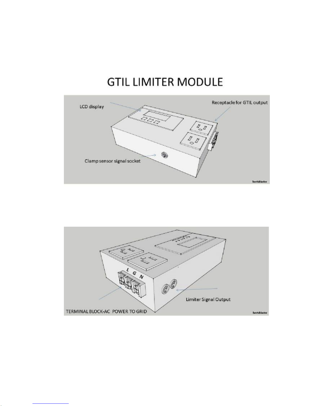
This isthe 2nd generationGTIL ofMasspower.The first generationGTIL mustbe used
withan additionallimitermodule,wealsoadd answitchbuttontoenablethe inverter
eithercanwork
at limit mode orat normalgrid tiemode. With the 2nd generation GTIL,we integrated the
limit functioninsidethe GTI-We callthisinternallimiter.In this way,Noadditionallimiter
moduleis needed,reduced customer scost,more easierforinstallation.Butin case
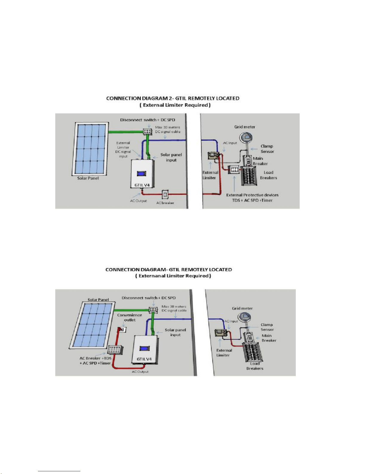
customerinstall inverterfarawayfromthe main circuitbreaker,wealso enable the 2nd
GTILworkwithstand-alone limiter,we callthis-externallimiter.Forsure,the invertercan
workundernormalGridtie-nolimitmode,just setontheniceLCD andsaveyoursetting.

1.On-GridSystemUsingStandard GridTieInverter
1.1.TheGridTieinverterconvertsDC powerproduced bySolarPanelsto AC,
connectstothe gridandfeedallofthepoweravailable fromthepanels to the
ACload.
1.2.All excesspowerthat is notneededbytheloadis then exported to theGrid.
1.3.IftheGridfails,thenthe Grid Tie Inverterwillturnoff.When the Grid comes
backon line. The Grid TieInverterwill again supplypowerto theloadandany
excess poweris exported to the Grid again.
1.4.IftheSolarPanelis producingless powerandtheGTIcannot deliverallthe
powerneededbytheload,then power
willbe supplementedbytheGrid.
1.5.PowerMeters(Exceptsmartmeter) arenotawareofthedirectionofPower
flow.Theuserthenpaysforthepowerexportedanddelivered bythe Grid.

2.On-GridSystemUsing Grid TieInverterWith Limiter(GTIL)
2.1 TheGrid TieInverterwith Limiterdeliversonlythepowerneededbythe load and
preventsdelivering excess powerhence avoidsexcesspoweringoing back to
theGrid.
2.2 TheheartoftheGridTie Inverterwith Limiteristhe LimiterModule (LM).TheLM
continuouslysampledthepowerneededbytheload through thecurrent sensor
connected aftertheMain Circuit Breaker.TheLMthenwill processthe signal.It
then sendssignaltoGrid TieInverterhowmuchpowertodeliverto theload in
realtime.
2.3 Theuser, afterinstalling andconnecting theGTIL correctly, neednot doanything
and theunit willdo itsworkautomatically.

3.The LimiterModule-PartsDescription

3.1.TheLCD Display
Displaysthe UtilityPower(grid power),InverterPower(GTIL power), UtilityKWH
and InverterKWH.
3.2.ACReceptacleForGTIL AC output
Two (2 pcs)-ConnectstheAC outputof GTIL to LM.Can beplug in either
receptacle. MaximumPowerperreceptacle is 2kworatotalof4kwGTILcanbe
plugged in thetworeceptacles.Theoutput of GTILcanalsobedirectly
connected to thegridorthroughthe house convenient outlet. ButtheLCD will
notdisplaythe InverterPower.
3.3.ClampSensor
Connects/clampsto onehot wireafterthe MainCircuit Breaker. Convertsthe
magneticfield createdbythe flow of currentin thewire into smallAC voltageand
current whichisproportionalto thepowerthatpassesthroughthewire.
3.4.ClampsensorAC signalsocket–connectsthe clamp sensorAC signalto the
LMmodule.
3.5.TerminalBlock-AC powertoGrid
TheAC output oftheGTIL is plugged to theLMreceptacle inorderforthe LCD
to displaytheGTIL outputinwattsand KWH. The GTIL outputis connected to
theGrid through theTerminalBlock. Connecting the terminalblocktoAC grid
alsopowersthewattmeterand limitercircuit.
3.6.LimiterDC SignalOutput, 2 pcs–Connectsthe LMoutput signaltotheGTIL
signalinput. Usercanconnectto anyofthesignaloutputreceptacle.

4. WIRINGDIAGRAMWITHEXTERNALLIMITER

4.1. The installationsof the GTILsystemareshown above,The acplugcaneither
connectto thenearbyAC socketorplug into thelimitersocket,thedcsignalcable can
reachmax30 meterslongth sothat youcanabletoinstalltheinverterfarawayfromthe
limitermodule.Theidealinstallationis thatthelimiterinstall neartheGTIL.TheGTIL
unitand theLimiterModule areplaced close to eachother.Thesignalwireswillbe
short, assuppliedwith theunit.
4.2.Usea dedicated20 AbreakerfortheGTIL in theLoad Circuitbreakerpanelboard
4.3. WiringandConnection Procedure
4.3.1.AftertheGTIL andLMareproperlyinstalled. Shut off the maincircuit
breaker.Connecttheclampsensorto onehot wireafterthe mainbreaker.
Connect theotherend ofclamp sensorsignalcabletothe LM.Neatlylayout the
signalcable. You can nowsafelyopen theMain breaker.
4.3.2 Connect the LMmodule to grid. Usingthe terminalblock, useat leastwire no.12
AWG(20Aampacity-wirenot includedin the package)andconnectto20A circuit

breakerdedicated fortheGTIL. Make surethe20Abreakeris off while wiring.Do
notturnonthebreaker!
4.3.3Connectthe DC signalcablefromLMtoGTILinput. The connectorshave
threadedscrewto securelyfastentheconnectorsplugatbothendsofthecable.
Alsotheconnectorplugshavedent/slotintheplugsbodysoitcanonlybe
connected in one direction orposition.
Step 3-ConnectingLimiter moduleDCoutputsignaltoGTIL
Usingthedcsignalcablewhichprovidedbysuppliertoconnecttheexternal
limiterconnectoroftheGTIL to thelimiterDC connector.DCoutputsignalsocket
inthelimitermoduleis markedAand B,you canconnectthe connectorofthe
cable to eitherAorB.Pluginandscrewin tolock.

Step4-Connectthe solar panelcableto the GTILDC input
4.3.5.Connect theSolarpaneloutput totheDC powerinputof GTIL. Make sure
the disconnectswitch/breakerof solarpanelisoff.
Beforeconnectingthe solarpanelcable,makesurethat the solarpanel
disconnectswitchorDCbreakerisoffandobservecorrectpolaritywhen
connectingthe cable.Failureto followwill causeseriousproblemwiththe unit.Pls
readthemanualbooklet oftheGTIincluded inthepackageforcorrectwireand
circuitbreaker/disconnectswitchrating.DonotturnontheDC circuit
breaker/disconnectswitch.
4.3.6.Reviewall connectionsandmakesure ofthe tightnessof plugsand
connections. Re-checkDC polarityconnectionsofsolarpanel.
4.3.7.Turnonthe20Acircuit breakertopowertheLimiterModule.
4.3.8.IntheLM, Press SETbuttonbelowthe LCD fora fewseconds.TheLCD
will lightupand initialize.

4.3.8.Afterinitialization, LCD willdisplayUtilityPower,whichis theactualpower
ortotalloadinrealtime.Presstheupand downbuttonstodisplaythe Inverter
Power, Utilitypower,UtilityTotalKWHand InverterTotalKWH. InverterPower
shouldreadzeroinitially.

To reset the UtilityTotal, just pressthe upbutton fora fewsecondsand you will
bepromptedyesornotoreset. Pressup ordown buttontoselecteitheryesor
no,andthenpressSETtoreset.
To reset InverterTotal, press thedownbutton continuouslyandyouwill
prompted yesornoalso to reset. Press upordown to selectyesornoand
PressSETtoreset.

4.3.9.ConnecttheGTIL poweroutputtothe LMAC receptacleusingthe
suppliedcable. Turn onthedisconnectswitch/dcbreakerofsolarpanel.
Thewattmeterinthe GTILshouldpowerupand startproducingpoweraftera
minute ortwo.
4.3.10 ChecktheLMdisplay. Theutilitypowershoulddisplay0-15windicating
theGTIL is alreadysupplying powerto theload.Checkthe inverterpowerdisplay
in the LCD.
4.3.11 To shutdown, turn-offorunplug first the GTIL beforedisconnectingthe
powerto limitermodule.Or shut offthebreakerto LMmodule to cut powerto
wholeset-up. Donot disconnect SolarpanelconnectiontoGTIL while thesystem
is operating.
4.3.12 In normaloperation,whentheunit is startedortheLMbreakeris turned
on,whileallthe cablesare connected andDC breakerison, therewillbeabout
2 minutesand20secondstime delaybeforetheGTILunitwillrun.Always

rememberthatforLMmodule to power-up,need to press Set buttonsfirst inthe
LMmodule forthe systemtorun.
5.Installation ofGTILWithInternalLimiter
5.1.This installation is notrequire an additionallimitermodule,Installation is much
easier.Clampthe current sensorcable to thehot wireto measurethe
current,theinternallimiterwillauto detecttheloadpowerandcontrolthe
inverteroutput power,excesspowerwillbewellcontrolled.
5.2.Externalprotective deviceincludingdcand acSPD(Surge protection
device),dcandacbreaker,etcis recommended to installedin thesystem.

Limiter SettingontheLCDof theinverter:
TheGTIL include threeworking mode:WorkasnormalGTIwithoutpower
limitation.WorkunderInternallimitermodeand WorkunderExternallimitermode,Pls
makeyoursettingontheLCD and saveit,details settingoperation,pls read the GTI
manual.
Theconnectorof Internal&ExternalLimiter:

Attention:Forexternal limitermode.Need tolongpresstheSETbutton
wheninitialpowerontheGTILsystemafterallconnectionsaredone.Due
togrid failureormalfunction,GTILsystemwillable toautorestartaftergrid
recover.
Aftersalesserviceandtechnicalsupport-Formoreinformation
aboutinstallation andotherconcerns,orif you havemore
questionsorclarification abouttheproduct.
6.0LimiterModuleSpecification
1.Clampsensor-Max100A
2.Wattmeter-Max9999w
3.TerminalBlock-Max20A
4.Receptacle-max2000w
5.Clampsensorsignal-5vACmaxmA
6.DC signal Cable-5vDC, ____ maxmA
Available MasspowerGTILModel
1000W -Model SUN-1000GTIL2-LCD
22-60VDC/45-90VDC,120VAC/230VAC
2000W-Model SUN-2000GTIL2-LCD
45-90VDC/230VAC
This manual suits for next models
1
Table of contents