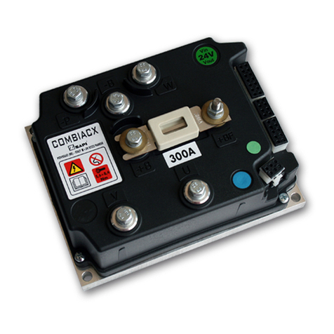
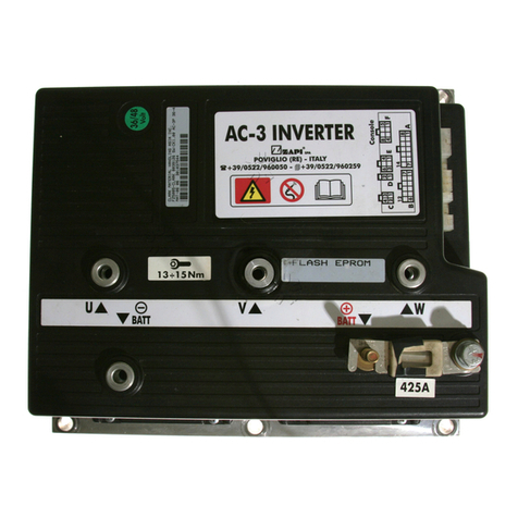
Zapi DUALAC2 User manual

Page 1
INDEX
1 Introduction............................................................................................................. 4
2 Specification ........................................................................................................... 5
2.1 Technical specifications - "Dualac2"................................................................ 5
2.2 Technical specifications - "Dualac2&hp" ......................................................... 6
2.3 Technical specifications - "Dualac2 Power"..................................................... 7
2.4 Technical specifications - "Dualac2&hp Power" .............................................. 8
2.5 Control unit ...................................................................................................... 8
2.5.1 Microswitches ........................................................................................ 8
2.5.2 Accelerator unit ...................................................................................... 8
2.5.3 Other analog control unit ......................................................................... 9
2.5.4 Speed feedback................................................................................... 10
2.5.5 Steering angle transducer ..................................................................... 10
2.6 Protection features ................................................................................. 12
2.7 Operational features ...................................................................................... 13
2.8 Diagnosis ..................................................................................................... 14
2.9 Thermal consideration ................................................................................... 14
2.10 General instructions and precautions ...................................................... 14
2.11 Susceptibility and electromagnetic emission ......................................... 15
2.12 Main contactor and emergency switch ........................................................... 15
3 Safety and protection ................................................................................... 16
4 Installation ............................................................................................................. 17
4.1 Connection cables ........................................................................................ 17
4.2 Contactors .................................................................................................... 17
4.3 Fuses ............................................................................................................ 17
4.4 Description of connectors - "Dualac2" and "Dualac2 Power" ........................ 18
4.5 Description of connectors - "Dualac2&hp" and "Dualac2&hp Power" ............ 20
4.6 Encoder installation ....................................................................................... 23
4.7 CANBUS connector description .................................................................... 24
4.7.1 "Dualac2" Controller in stand-alone configuration.................................. 24
4.7.2 "Dualac2" Controller is a termination module in the canbus net ............. 24
4.7.3 "Dualac2" Controller is a repetition module in the canbus net ................ 25
4.8 Description of power connections.................................................................. 26
4.8.1 "Dualac2" ............................................................................................. 26
4.8.2 "Dualac2 Power" .................................................................................. 27
4.8.3 "Dualac2&hp"....................................................................................... 28
4.8.4 "Dualac2&hp Power" ............................................................................ 30
4.9 Mechanical drawing ...................................................................................... 32
4.10 Connection drawing - "Dualac2" and "Dualac2 Power" standalone ................ 36
4.11 Connection drawing - "Dualac2&hp" and "Dualac2&hp Power" standalone ... 37

Page 2
5 Programming & Adjustments using Digital Console ......................................... 38
5.1 Adjustments via Console ............................................................................... 38
5.2 Description of Console & Connection ............................................................ 38
5.3 Description of Standard Console Menu ......................................................... 39
5.3.1 "Dualac2" and "Dualac2 Power" menu configuration ............................ 39
5.3.1.a Master ............................................................................................... 39
5.3.1.b Slave ................................................................................................. 40
5.3.2 "Dualac2&hp" and "Dualac2&hp Power" menu configuration ................ 41
5.3.2.a Master ............................................................................................... 41
5.3.2.b Slave ................................................................................................. 42
5.4 Function configuration ................................................................................... 43
5.4.1 "Dualac2" and "Dualac2 Power" - Master ............................................. 43
5.4.2 "Dualac2" and "Dualac2 Power" - Slave ............................................... 46
5.4.3 "Dualac2&hp" and "Dualac2&hp Power" - Master ................................ 47
5.4.4 "Dualac2&hp" and "Dualac2&hp Power" - Slave .................................. 47
5.5 Parameter regulation ..................................................................................... 52
5.5.1 "Dualac2" - Master ............................................................................... 52
5.5.2 "Dualac2" - Slave ................................................................................. 53
5.5.3 "Dualac2&hp" - Master ......................................................................... 54
5.5.4 "Dualac2&hp" - Slave ........................................................................... 55
5.6 Programming console functions .................................................................... 60
5.6.1 Functional configuration (see 5.4) ......................................................... 60
5.6.2 Parameter programming (see 5.5) ....................................................... 60
5.6.3 "Dualac2" and "Dualac2 Power" Tester: user can verify the state of the
following parameters: .................................................................................... 60
5.6.4 "Dualac2&hp" and "Dualac2&hp Power" Tester: user can verify the state
of the following parameters: ........................................................................... 61
5.6.5 Save function (for storing data) --> only with Pc-console ........................ 61
5.6.6 Restore function (for downloading parameters to another controller) -->
only with Pc-console ...................................................................................... 61
5.6.7 Display of the last 5 alarms including hour-meter value and temperature at
the moment of the alarm. ............................................................................... 61
5.6.8 Accelerator range programming ........................................................... 61
5.6.9 See the console manual for a detailed description of function and param-
eters.............................................................................................................. 61
5.7 Sequence for Ac Inverter Traction setting....................................................... 62
5.8 Tester: description of the function .................................................................. 63
5.8.1 "Dualac2" and "Dualac2 Power" - Master ............................................. 63
5.8.2 "Dualac2" and "Dualac2 Power" - Slave ............................................... 64
5.8.3 "Dualac2&hp" and "Dualac2&hp Power" - Master ................................ 65
5.8.4 "Dualac2&hp" and "Dualac2&hp Power" - Slave .................................. 66
6 Other functions ..................................................................................................... 69
6.1 Save and Restore function............................................................................. 69
6.2 Description of Alarms menu .......................................................................... 70
6.3 Description of Console Program Vacc function ............................................. 71

Page 3
= The informations included into the marked paragraphs by this symbol are
essential for the safety.
SIGNATURES TABLE
COM PANY DEPT. SERVICES M ANAGEM ENT EXECUTIVE
ENGINEERING SECTION EXECUTIVE
EXPORT MANAGER
Publications N°: AE9ZP0BA
Edition: March 2003
7 "Dualac2" and "Dualac2&hp" Inverter diagnostic ............................................ 72
7.1 Traction related fault codes ........................................................................... 72
7.2 Analysis of traction related alarms displayed on console................................ 76
7.3 Pump related fault codes ............................................................................... 81
7.4 Analysis of pump related alarms displayed on console .................................. 82
8 Recommended Spare parts for inverter ............................................................. 83
9 Periodic Maintenance to be repeated at times indicated ................................... 84

Page 4
1 INTRODUCTION
Within the ZAPIMOS family, the DUALAC2 inverter is the model suitable for control of pairs
of 3.0kW to 7.0kW motors. The DUALAC2&HP can also control a DC-Series pump motor,
up to 15kW. These controllers have been expressly designed for battery powered applica-
tions, traction and hydraulic functions. They are fit for electric trucks, utility cars, tractors.

Page 5
2 SPECIFICATION
2.1 TECHNICAL SPECIFICATIONS - "DUALAC2"
Inverter for pairs of AC asynchronous 3-phase motors
Regenerative braking functions
Can-bus interface
Digital control based upon a microcontroller (one per each motor)
Voltage: .................................................................................. 24 - 36 - 48 - 72 - 80V
Maximum current (24V): ........................................ 350A (RMS) for 3' per each motor
Maximum current (36/48V): ................................... 275A (RMS) for 3' per each motor
Maximum current (72/80V): ................................... 200A (RMS) for 2' per each motor
Operating frequency: ..........................................................................................8kHz
External temperature range: ................................................................. -30°C ÷ 40°C
Maximum inverter temperature (at full power): .................................................... 75°C
BLOCK DIAGRAM

Page 6
2.2 TECHNICAL SPECIFICATIONS - "DUALAC2&HP"
Inverter for pairs of AC asynchronous 3-phase motors plus chopper for DC series pump
motor.
Regenerative braking functions
Can-bus interface
Digital control based upon a microcontroller (one per each AC motor)
Voltage: .................................................................................. 24 - 36 - 48 - 72 - 80V
Maximum current (24V): ........................................ 350A (RMS) for 3' per each motor
Maximum current (36/48V): ................................... 275A (RMS) for 3' per each motor
Maximum current (72/80V): ................................... 200A (RMS) for 2' per each motor
Chopper maximum current (24V): ............................................................. 500A for 2'
Chopper maximum current (36/48V): ........................................................ 420A for 2'
Chopper maximum current (72/80V): ........................................................ 300A for 2'
Operating frequency: ..........................................................................................8kHz
External temperature range: ................................................................. -30°C ÷ 40°C
Maximum inverter temperature (at full power): .................................................... 75°C
BLOCK DIAGRAM

Page 7
BLOCK DIAGRAM CHOPPER
2.3 TECHNICAL SPECIFICATIONS - "DUALAC2 POWER"
Inverter for pairs of AC asynchronous 3-phase motors
Regenerative braking functions
Can-bus interface
Digital control based upon a microcontroller (one per each AC motor)
Voltage: .................................................................................. 24 - 36 - 48 - 72 - 80V
Maximum current (24V): ........................................ 450A (RMS) for 3' per each motor
Maximum current (36/48V): ................................... 350A (RMS) for 3' per each motor
Maximum current (72/80V): ................................... 275A (RMS) for 2' per each motor
Operating frequency: ..........................................................................................8kHz
External temperature range: ................................................................. -30°C ÷ 40°C
Maximum inverter temperature (at full power): .................................................... 75°C
BLOCK DIAGRAM
See chapter 2.1 - Block Diagram.

Page 8
2.4 TECHNICAL SPECIFICATIONS - "DUALAC2&HP POWER"
Inverter for pairs of AC asynchronous 3-phase motors plus chopper for DC series pump
motor
Regenerative braking functions
Can-bus interface
Digital control based upon a microcontroller (one per each AC motor)
Voltage: .................................................................................. 24 - 36 - 48 - 72 - 80V
Maximum current (24V): ........................................ 450A (RMS) for 3' per each motor
Maximum current (36/48V): ................................... 350A (RMS) for 3' per each motor
Maximum current (72/80V): ................................... 275A (RMS) for 2' per each motor
Chopper maximum current (24V): ............................................................. 500A for 2'
Chopper maximum current (36/48V): ........................................................ 420A for 2'
Chopper maximum current (72/80V): ........................................................ 300A for 2'
Operating frequency: ..........................................................................................8kHz
External temperature range: ................................................................. -30°C ÷ 40°C
Maximum inverter temperature (at full power): .................................................... 75°C
BLOCK DIAGRAM
See chapter 2.2 - Block Diagram.
2.5 CONTROL UNIT
2.5.1 Microswitches
- The microswitches must have a contact resistance lower than 0.1ohm and a leakage
current lower than 100µA.
- When full load connected, the voltage between the key switch contacts must be lower
than 0.1V.
- The microswitches send a voltage signal to the microprocessor when a function request
(for ex.: running request) is made.
2.5.2 Accelerator unit
The accelerator unit can consist of a potentiometer or an Hall effect device.
It should be in a 3-wire configuration.
CPOT (C21) signal ranges from 0 to 10V.
Potentiometer value should be in the 0.5 - 10 Kohm range; generally, the load should be in
the 1.5mA to 30 mA range. Faults can occur if it is outside this range.

Page 9
PPOT is the accelerator unit positive supply. It can be either a 5V output or a 10V output.
The selection of the output voltage is made in the logic card by moving a jumper (factory
set).
NPOT is the accelerator unit negative supply. This output is feedback to the µC A/D con-
verter to test the continuity of the accelerator unit circuit (test of poti wire disconnection).
The Procedure for automatic potentiometer signal acquisition is carried out using the
Console. This enables adjustment of the minimum and maximum useful signal level
(PROGRAM VACC function), in either direction. This function is unique when it is neces-
sary to compensate for asymmetry with the mechanical elements associated with the
potentiometer, especially relating to the minimum level.
The sequence of procedure is described in the programming console manual.
The two graphs show the output voltage from a non-calibrated potentiometer with
respect to the mechanical “zero” of the control lever. MI and MA indicate the point where
the direction switches close. 0 represents the mechanical zero of the rotation.
The Left Hand graph shows the relationship of the motor voltage without signal acquisition
being made. The Right Hand Graph shows the same relationship after signal acquisition
of the potentiometer.
2.5.3 Other analog control unit
1) Input C18 is an analog input, whose typical application is for proportional braking. It
should be in a 3 wire configuration. Potentiometer value should be in the 0.5-10 Kohm
range. Generally, the load should be in the 1.5mA to 30 mA range.
The CPOTB (C18) signal range is from 0 to 5V or from 0V to 10V.
2) Connections C25 (PTHERMR) and C24 (NTHERMR) are used for the right motor
thermal sensor. Connections C35 (PTHERML) and C34 (NTHERML) are used for the
left motor thermal sensor. Sensors can be digital (on/off sensor, normally closed) or
analog. See also chapter 5.4 for more explanation.
3) In the versions with integrated pump chopper (DUALAC2&HP and DUALAC2&HP
POWER), it is possible to input to the controller an analog signal for proportional lifting.
This input will be the output of a potentiometer (3 wires, resistance in the 1 to 10kohm
range) or of a Hall Effect device; the load must be below 10mA. CPOTLIFT (D9) signal
has to be within the 0 to 10V range.

Page 10
2.5.4 Speed feedback
The traction motors control is based upon the motor speed feedback. The speed trans-
ducer is an incremental encoder, with two phases shifted at 90°. The encoder can be of
different types :
- power supply: +5V or +12V
- electric output: open collector ( NPN or PNP), push-pull
For more details about encoder installation see also chapter 4.6.
2.5.5 Steering angle transducer
Angular position of steered wheels is transduced to an electric information (voltage) by
means of a potentiometer, with following characteristics:
- resistance in the 2kohm to 20kohm range;
- suggested rotation electric angle: at least 300°;
- positive supply: 5V or 10V;
- potentiometer has to be installed in a way that in the "zero" position (straight wheels),
poti output voltage is in the middle of the electric range corresponding to a full left-to-
right transition of the steered wheels;
- install the potentiometer in a way that, when truck turns right, poti output voltage in-
creases;
- use "SET STEER MIN" and "SET STEER MAX" functions to record the extremes (mini-
mum and maximum) of the potentiometer range; see chapter 5.4.
- use "SET STEER 0-POS" function to record the poti output when the steered wheels
are straight; see chapter 5.4.
MOTOR MANAGEMENT TABLE

Page 11
Potentiometer connections
Steering table
The relationship between the two motors speed changes as a function of the steering
angle and of the axle/wheeltrack ratio.
While the steering angle is an information coming from the trasducer (potentiometer), the
axle/wheeltrack ratio is a constant characteristic of the truck that depends on his dimen-
sions. Actually two steering tables are provided:
Option #1 = tables for 3 wheels trucks with driving wheels counter-rotation (the internal
wheel inverts the direction).
Option #2 = tables for 4 wheels trucks without driving wheels counter-rotation (the
internal wheel does not inverts the direction).
The truck data have to be communicated to Zapi, so that it is possible to put in the software
the correct steering table.
The correct table selection is done in the SET OPTION menu, see chapter 5.4.
The relationship between the two motors speed is equal to the relationship between the
two radius described during the curve.

Page 12
2.6 PROTECTION FEATURES
- Battery polarity inversion:
It is necessary to fit a MAIN CONTACTOR to protect the inverter against reverse battery
polarity and for safety reasons.
- Connection Errors:
All inputs are protected against connection errors.
- Thermal protection
If the chopper temperature exceeds 75°C, the maximum current is reduced in
proportion to the thermal increase. The temperature can never exceeds 100°C.
- External agents:
The inverter is protected against dust and the spray of liquid to a degree of
protection meeting IP54.
- Protection against uncontrolled movements:
The main contactor will not close if:
- The Power unit is not functioning.
- The Logic is not functioning perfectly.
- the output voltage of the accelerator does not fall below the minimum voltage value
stored, with 1V added.
- Running microswitch in closed position.
-Low battery charge:
when the battery charge is low, the maximum current is reduced to the half of the maxi-
mum current programmed.
- Protection against accidental Start up
A precise sequence of operations are necessary before the machine will start.
Operation cannot begin if these operations are not carried out correctly.
Requests for drive, must be made after closing the key switch

Page 13
2.7 OPERATIONAL FEATURES
- Speed control.
- Optimum behaviour an a slope due to the speed feedback:
- the motors speed follows the accelerator, starting a regenerative braking if the speed
overtakes the speed set-point.
- the system can perform an electrical stop on a ramp (the machine is electrically hold
on a slope) for a programmable time (see also chapter 5.4)
- Stable speed in every position of the accelerator.
- Electronic differential feature with torque balance between external and internal wheel.
- Regenerative release braking based upon deceleration ramps.
- Regenerative braking when the accelerator pedal is partially released (deceleration).
- Direction inversion with regenerative braking based upon deceleration ramp.
- Regenerative braking and direction inversion without contactors: only the main
contactor is present.
- The release braking ramp can be modulated by an analog input, so that a proportional
brake feature is obtained.
- Optimum sensitivity at low speeds.
- Voltage boost at the start and with overload to obtain more torque (with current control).
- The inverter can drive an electromechanical brake
- Hydraulic steering function:
- the traction inverter sends a "hydraulic steering function" request to the pump inverter
on the can-bus line.
- moreover , if the pump inverter is not present (for ex: tractor application), the traction
inverter can manage an "hydraulic steering function" by driving a hydro contactor which
drive a hydraulic steering motor (output C31).
- High efficiency of motor and battery due to high frequency commutations.
- Modification of parameters through the programming console.
- Internal hour-meter with values that can be displayed on the console.
- Memory of the last five alarms with relative hour-meter and temperature displayed on the
console.
- Diagnostic function with Zapi handset for checking main parameters.
- Built in BDI feature.
- Flash memory, sw downloadable via serial link and via CANBUS.
- Canopen interface available.

Page 14
2.8 DIAGNOSIS
The microprocessors continually monitor the inverter and carry out a diagnostic procedure
on the main functions. The diagnosis is made in 4 points
1) Diagnosis on key switch closing that checks: watchdog circuit, current sensor, capaci-
tor charging, phase's voltages, contactor drivers, can-bus interface, if the switch se-
quence for operation is correct and if the output of accelerator unit is correct, correct
synchronization of the two µCS, integrity of safety related inputs hardware.
2) Standby diagnosis at rest that checks: watchdog circuit, phase's voltages, contactor
driver, current sensor, can-bus interface.
3) Diagnosis during operation that checks: watchdog circuits, contactor driver, current
sensors, can-bus interface.
4) Continuos diagnosis that check: temperature of the inverter, motor temperature.
Diagnosis is provided in two ways. The digital console can be used, which gives a detailed
information about the failure; the failure code is also sent on the Can-Bus.
2.9 THERMAL CONSIDERATION
- The heat generated by the power block must be dissipated. For this to be possible,
the compartment must be ventilated and the heat sink materials ample.
- The heat sink material and system should be sized on the performance requirement of
the machine. Abnormal ambient air temperatures should be considered. In situations
where either ventilation is poor, or heat exchange is difficult, forced air ventilation should
be used.
- The thermal energy dissipated by the power block module varies and is dependent on
the current drawn and the duty cycle.
2.10 GENERAL INSTRUCTIONS AND PRECAUTIONS
- Never connect SCR low frequency chopper with ASYNCHRONOUS INVERTER be-
cause the ASYNCHRONOUS filter capacitors alter the SCR choppers' work. If it is
necessary to use two or more control units (traction + lift. for ex.), they must belong to the
ZAPIMOS family.
- Do not connect the inverter to a battery with a nominal value different from the value
indicated on the chopper plate. If the battery value is greater, the MOS may fail; if it is
lower, the control unit does not "power up".
- During battery charge, disconnect ASYNCHRONOUS from the battery.
- Supply the ASYNCHRONOUS only with battery for traction; do not use a power supply.
- When the chopper is installed, make tests with the wheels raised from the ground, in
order to avoid dangerous situations due to connection errors.
- After the chopper is switched off (key off), the filter capacitor remains charged for about
1 minute; if you need to work on the inverter, discharge them using a
10W ÷ 100W resistance connected from the +Batt to the -Batt.

Page 15
2.11 SUSCEPTIBILITY AND ELECTROMAGNETIC EMISSION
Electromagnetic susceptibility and emission are strongly influenced by the installation.
Special attention must be given to the lengths and the paths of the electric connections and
the shields.
This situation is beyond ZAPI's control. Therefore ZAPI declines any responsibility for
noncompliance if correct testing is not made (the irradiated emission directive is
EN50081-2).
2.12 MAIN CONTACTOR AND EMERGENCY SWITCH
- The connection of the battery line switches must be carried out following ZAPI instruc-
tions.
- If a mechanical battery line switch is installed, it is necessary that the key supply to the
inverter is open together with power battery line; if not, the inverter may be
damaged if the switch is opened during a regenerative braking.
- An intrinsic protection is present inside the logic when the voltage on the battery power
connection overtakes 40% more than the battery nominal voltage or if the key is
switched off before the battery power line is disconnected.

Page 16
3 SAFETY AND PROTECTION
ZAPI controllers are designed according to the prEN954-1 specifications for safety
related parts of control system and to UNI EN1175-1 norm.
The safety of the machine is strongly related to installation; length, layout and
screening of electrical connections have to be carefully designed.
Dualac2 controller electronic implements double hardware circuit for four inputs: Seat (C5),
Forward (C6), Reverse (C7), Accelerator Enable (C8).
These signals are input, through two hardware independent circuits, to both
microcontrollers which implement a cross-check of the input status, thus preventing an
abnormal behaviour due to a failure in the input hardware.
It is strongly suggested to connect the machine safety related devices to these
four inputs, in order to increase machine safety.
ZAPI is always available to cooperate with the customer in order to evaluate instal-
lation and connection solutions. Furthermore, ZAPI is available to develop new
SW or HW solutions to improve the safety of the machine, according to customer
requirements.
Machine manufacturer holds the responsibility for the truck safety features and
related approval.

Page 17
4 INSTALLATION
Install the controller with the base-plate on a flat metallic surface that is clean and
unpainted. Apply a light layer of thermo-conductive grease between the two surfaces to
permit better heat dissipation.
Ensure that the wiring of the cable terminals and connectors is carried out correctly.
Fit transient suppression devices to the horn, solenoid valves, and contactors not con-
nected to the chopper such as those for activating the pump motor or steering motor.
4.1 CONNECTION CABLES
For the auxiliary circuits, use cables of 0.5mm² section.
For power connections to the motor and to the battery, use cables having section
of 35 mm² (as a minimum).
For the optimum inverter performance, the cables to the battery should be run side by side
and be as short as possible.
4.2 CONTACTORS
The main contactor must be installed. The LC coil driver is voltage controlled by means of
a 1 khz PWM. The voltage applied to the coil can be adjusted by "Main Cont Voltage"
parameter in Config/Adjustment menu. It has to be adjusted to the LC coil nominal voltage.
4.3 FUSES
- Use a 6.3A Fuse for protection of the auxiliary circuits.
- For protection of the power unit, refer to diagrams.. The Fuse value shown is the maxi-
mum allowable. For special applications or requirements these values can be reduced.
- For Safety reasons, we recommend the use of protected fuses in order to prevent the
spread of fused particles should the fuse blow.

Page 18
4.4 DESCRIPTION OF CONNECTORS - "DUALAC2" AND "DUALAC2 POWER"
A1 CAN_H High level CANBUS.
A2 CANT_H CANBUS termination output, 120 ohm internally connected to
CAN_H. Connect to CAN_L_OUT to insert the termination.
A3 CAN_POS Positive of CAN circuit; to be used in case of optoisolated
CANBUS.
A4 CAN_L_OUT Low level CANBUS: to be used as repetition for CAN_L line or to be
connected to CANT_H to insert termination resistance.
A5 CANT_L CANBUS termination output, 120 ohm internally connected to
CAN_L. Connect to CAN_H_OUT to insert the termination.
A6 CAN_L Low level CANBUS.
A7 CAN_H_OUT High level CANBUS: to be used as repetition for CAN_H line or to
be connected to CANT_L to insert termination resistance.
A8 CAN_NEG Negative of CAN circuit, to be used in case of optoisolated
CANBUS.
B1 PCLRXD Positive serial reception.
B2 NCLRXD Negative serial reception.
B3 PCLTXD Positive serial transmission.
B4 NCLTXD Negative serial transmission.
B5 GND Negative console power supply.
B6 +12 Positive console power supply.
B7 FLASH
B8 FLASH

Page 19
C1 PENC_R Positive of right motor encoder power supply (+5V/+12V).
C2 NENC_R Negative of right motor encoder power supply.
C3 KEY Connected to +Batt trough a microswitch and a 10A fuse in series.
C4 CM Common of FW / REV / HB / PB / SEAT / ENABLE microswitches.
C5 SEAT Seat presence signal; active high.
C6 FORWARD Forward direction request signal; active high.
C7 REVERSE Reverse direction request signal; active high.
C8 ENABLE Traction request signal; active high.
C9 PB Pedal brake request signal; active high.
C10 SR/HB Speed reduction signal or hand brake input; active low (microswitch
open). See also chapter 5.4.
C11 PENC_L Positive of left motor encoder power supply (+5V/+12V).
C12 NENC_L Negative of left motor encoder power supply.
C13 PHA_R Right motor encoder phase A.
C14 PHB_R Right motor encoder phase B.
C15 NPOTST Negative of steering potentiometer (-BATT).
C16 PPOTST Positive of steering potentiometer (+5V/+12V).
C17 CPOTST Steering potentiometer wiper signal.
C18 CPOTB Brake potentiometer wiper signal.
C19 NPOTB -BATT.
C20 NPOT Negative of traction accelerator potentiometer, tested for wire dis-
connection diagnosis.
C21 CPOT Traction potentiometer wiper signal.
C22 PHA_L Left motor encoder phase A.
C23 PHB_L Left motor encoder phase B.
C24 NTHERM_R Negative of right traction motor temperature sensor.
C25 PTHERM_R Right traction motor temperature signal.
C26 NLC Output of main contactor coil driver (drives to -BATT).
C27 PLC Positive of main contactor coil.
C28 NBRAKE Output of electric brake coil; drives the load to -BATT, maximum
current 3A.
C29 PBRAKE Positive of the electromechanical brake coil.
C30 PAUX Positive of auxiliary load.
C31 NAUX Output of auxiliary load driver (drives to -BATT).
C32 -BATT
C33 PPOT Traction potentiometer positive, 5/10V output; use load > 1k ohm.
C34 NTHERM_L Negative of left traction motor temperature sensor.
C35 PTHERM_L Left traction motor temperature signal.

Page 20
4.5 DESCRIPTION OF CONNECTORS - "DUALAC2&HP" AND "DUALAC2&HP
POWER"
A1 CAN_H High level CANBUS.
A2 CANT_H CANBUS termination output, 120 ohm internally connected to
CAN_H. Connect to CAN_L_OUT to insert the termination.
A3 CAN_POS Positive of CAN circuit; to be used in case of optoisolated
CANBUS.
A4 CAN_L_OUT Low level CANBUS: to be used as repetition for CAN_L line or to be
connected to CANT_H to insert termination resistance.
A5 CANT_L CANBUS termination output, 120 ohm internally connected to
CAN_L. Connect to CAN_H_OUT to insert the termination.
A6 CAN_L Low level CANBUS.
A7 CAN_H_OUT High level CANBUS: to be used as repetition for CAN_H line or to
be connected to CANT_L to insert termination resistance.
A8 CAN_NEG Negative of CAN circuit, to be used in case of optoisolated
CANBUS.
B1 PCLRXD Positive serial reception.
B2 NCLRXD Negative serial reception.
B3 PCLTXD Positive serial transmission.
B4 NCLTXD Negative serial transmission.
B5 GND Negative console power supply.
B6 +12 Positive console power supply.
B7 FLASH
B8 FLASH
Table of contents
Other Zapi Inverter manuals
Popular Inverter manuals by other brands

Power Electronics
Power Electronics SD 500 Series Hardware and installation manual

Xantrex
Xantrex PV-100208 Operation and maintenance manual

TerraGen
TerraGen TGR installation manual

Dometic
Dometic CK36H401RI Harrier Inverter installation manual

DeWalt
DeWalt DXAEPI1000 instruction manual

Well
Well Well Triumph 230V 500VA 300W instruction manual