Master audio KEY8 User manual

KEY8 / KEY12 / KEY15 / KEY18W
Pol.Ind.Norte-Perpinyà,25
08226 TERRASSA (Barcelona-SPAIN)
All rights reserved www.master-audio.com
Jan 14
User’s manual / Manual usuario

Master Audio
KEY Series (Passive). Version 1.0 Jan14 2
ENGLISH
1. INTRODUCTION
1.1. General
Master Audio would like to thank you for your confidence in our KEY Series. We
suggest you to read the following instructions carefully in order to obtain the best
performance.
1.2. Features and presentation
KEY8
- Two-way Full Range Speaker System
- 8" woofer with kevlar cone and 1.5” voice coil
- 1" titanium diaphragm neodymium tweeter
- Accurate designed crossover to achieve the best performance
- 240W musical program
- Sensitivity: 93 dB (1W/1m)
KEY12
- Two-way Full Range Speaker System
- 12" woofer with 2” voice coil
- 1” kevlar diaphragm driver
- 70º (H) x 40º (V) dispersion horn
- Accurate designed crossover to achieve the best performance
- 400W musical program
- Sensitivity: 97 dB (1W/1m)
KEY15
- Two-way Full Range Speaker System
- 15" woofer with 2.5” voice coil
- 1” kevlar diaphragm driver
- 70º (H) x 40º (V) dispersion horn
- Accurate designed crossover to achieve the best performance
- 500W musical program
- Sensitivity: 98 dB (1W/1m)
KEY18W
- Low frequency reinforcement unit
- 18" woofer with 4” voice coil
- 1000W musical program
- Sensitivity: 97 dB (1W/1m)
- Passive-parallel or bi-amplified use with KEY8/KEY12/KEY15

Master Audio
KEY Series (Passive). Version 1.0 Jan14 3
2. CONNECTIONS
2.1. Connection description
Fig.1. KEY (passive) connectors
(1)-SPEAKON: All models use two Speakon terminals and are duly prepared for a
perfect connection in a parallel system. Terminal pins +1/-1 must be always used,
disregarding the +2/-2 which are not internally connected.
WARNING: It is strongly recommended to use a two-conductor high quality wire, non-
shielded and two-coloured. We recommend using a minimum section of 4mm2for
each conductor. Avoid long wire distances as they induce to important power and
quality losses
2.2. Configurations
2.2.1. Full Range Stereo configuration
Connect each output of the amplifier LEFT/RIGHT to each cabinet using two
independent wires.
Fig.2. Full range stereo configuration

Master Audio
KEY Series (Passive). Version 1.0 Jan14 4
2.2.2. Full Range Parallel
configuration
Connect the amplifier's output to
the Speakon’s input of the first
cabinet, always respecting the
polarity positive +1, negative -1.
Then, make a bridge from the first
cabinet to the second one. This
configuration allows you to connect
up to four cabinets to the same
amplifier.
Fig.3. Full range parallel configuration
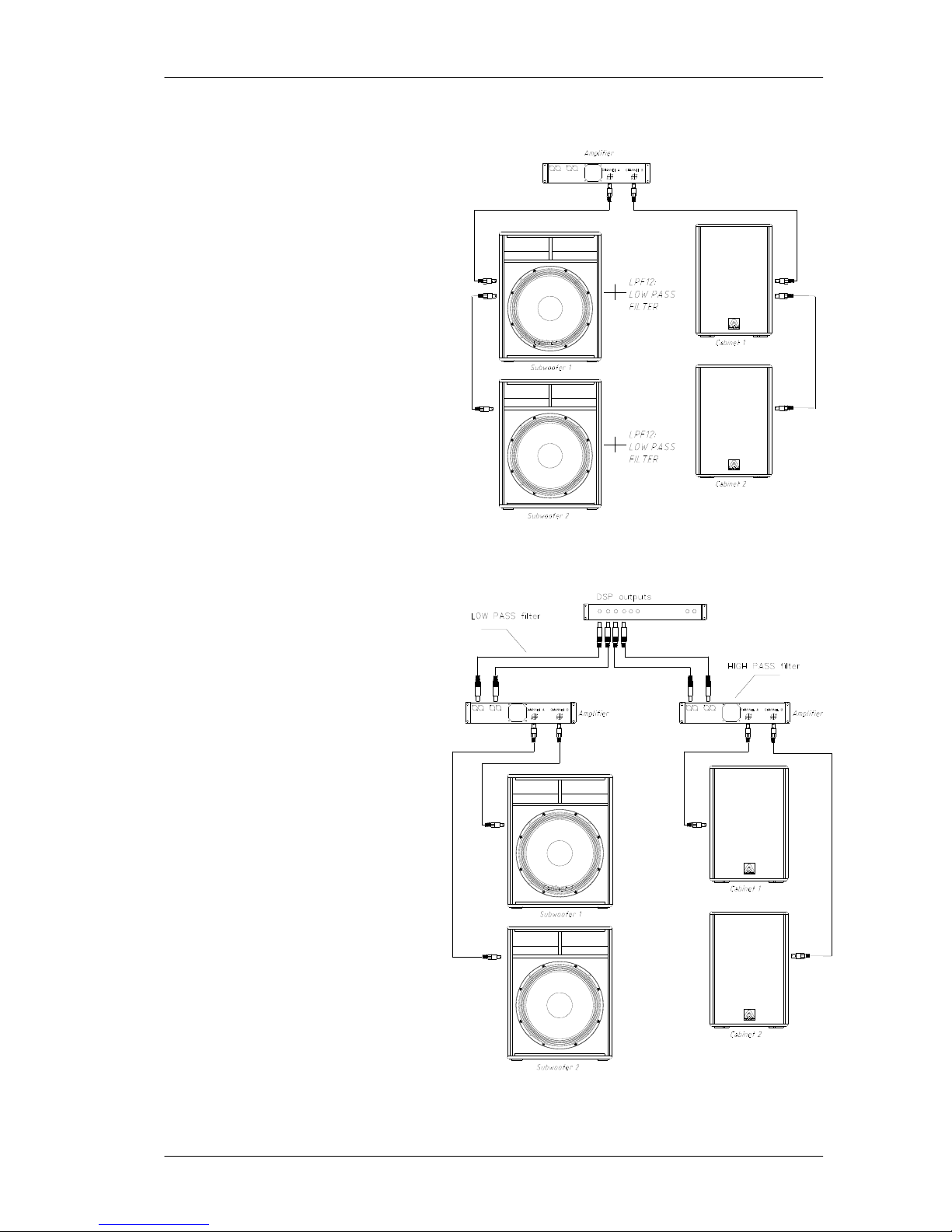
2.2.3. Passive configuration with Subwoofer
There will be times when you will be
interested in reinforcing your KEY
systems with subwoofer units, in passive
mode. In this case only one amplifier will
be used for the whole system.
Connect one of the outputs of the
amplifier to the subwoofer through a wire.
Then, make a bridge from the slave
Speakon connector of the subwoofer to its
respective mid-high top unit, always
respecting the correct polarity between
both systems. Do the same with the other
channel. It is also correct, if the
installation requires so, to make the
connection in the opposite way, that is,
from the amplifier to the satellite and then
to the subwoofer.
Note: when using this configuration, make
sure to use a LPF (Low pass filter) on the
subwoofer unit (refer to “LPF12
accessory”).
Fig.4. Passive with subwoofer configuration

Master Audio
KEY Series (Passive). Version 1.0 Jan14 5
2.2.4. Bi-Amplified configuration with Subwoofer
A wire with the maximum available
section (4mm2minimum) should
link the low frequencies output
channel of the amplifier to one of
the subwoofers. Two subwoofers
can be also connected by bridge
one to another, as long as the
polarity is strictly respected.
Connect the other output of the
amplifier to the Full Range
cabinets.
Note: when using this
configuration, make sure to use a
LPF (Low pass filter) on the
subwoofer units (refer to “LPF12
accessory”).
Fig.5. Bi-amplified with subwoofer configuration (option 1)
It is also possible to use only one
amplifier for the low
reinforcement units, connecting
each one of the subwoofers to
the two outputs of the amplifier
and consequently, connecting the
Full Range cabinets to a second
amplifier.
Note: when using this
configuration, make sure to use
an external DSP with a low pass
filter for the subwoofer units and
a high pass filter for the full-range
cabinets.
Fig.6. Bi-amplified with subwoofer configuration (option 2)

Master Audio
KEY Series (Passive). Version 1.0 Jan14 6
WARNING!!!!: In order to allow a bridge connection between cabinets, each one of
them has been provided with two Speakon connectors that allow the Input / Output
function indistinctly. Terminal pins +1/-1 must be always used, disregarding the +2/-2
which are not internally connected.
3. MOUNTING AND PLACEMENT
For a proper installation of the acoustic cabinets, it is strongly recommended to read
carefully the following advices.
3.1. Placement
The Full Range cabinets should be located in a high
position (between two or three meters), slightly inclined to
the audience. If the loudspeakers are located too low, the
listeners at the end of the room will not hear a good sound
quality.
Fig.7. Flying placement
It is advisable to locate the subwoofer units on the floor as they can take advantage
of the so-called “floor-effect”, thus increasing the response in the low frequencies.
If possible, place the subwoofers under the same acoustic axis used for the satellites.
If the above option cannot be carried out, then they should be placed in an
intermediate point between the left and right channels.
3.2. Tripod use
The KEY8, KEY12 and KEY15 models
are equipped with a tripod socket (A) for
use with a standard 35mm tripod.
Do not use the tripod on non-flat floors
and be careful not to raise the cabinet too
high on the tripod, as it may become
unstable.
Fig.8. Full range cabinet with tripod

Master Audio
KEY Series (Passive). Version 1.0 Jan14 7
3.3. Full range cabinet with subwoofer
The KEY18W is equipped with a
M20 Plate (A) for a 35mm distance
rod. You can use it to place over the
subwoofer the models that are
equipped with the tripod socket
(KEY8, KEY12 and KEY15). Be
careful not to use this system on
non-flat surfaces as it may become
unstable.
Fig.9. Full range cabinet with
subwoofer
3.4. Live applications (mobile)
For a mobile application, whether it is
an outdoor or indoor installation, the
common location is to place the bass
units (one or two per channel) on each
side of the stage.
Fig.10. Mobile applications
To obtain a clear and free-distortion reproduction, it is advisable to place the mid-high
units on top of the low units keeping between them an approximate height of two
meters. If such height cannot be achieved nor maintained, it is advisable to use the
classical tripod for each mid-high cabinet and leave the low units on the floor.
WARNING!!! For installations that suffer from acoustic problems and in which it is
necessary to reinforce the response in the low frequencies, it is advisable to group all
the subwoofers together in the same point. By this way, cancellations will be avoided
and a higher acoustic pressure level will be obtained.

Master Audio
KEY Series (Passive). Version 1.0 Jan14 8
3.5. Stage monitor use
The KEY12 and KEY15 models have
trapezoidal shape so, they can be used
as floor monitors without extra
accessories.
Fig.11. Stage monitor use
3.6. Rotatable logo
KEY8, KEY12, KEY15 and KEY18W model logos can be rotated.
3.7. Flying
Only experienced people should fly speaker cabinets. Extreme care should be taken
to assure the load bearing capabilities of the structures where the cabinets will be
placed. Hanging hardware (as chains, eyebolts, lock pins...) should be regularly
inspected and replaced if in doubt.
WARNING!!! DO NOT SUSPEND THE CABINETS FROM THE HANDLES!!!!
3.7.1. KEY8, KEY12 and KEY15 horizontal flying with “U” bracket
The KEY8 may be wall mounted by the SP8 “U” bracket accessory.
The KEY12 may be wall mounted by the SP12 “U” bracket accessory.
The KEY15 may be wall mounted by the SP15 “U” bracket accessory
Fig.12. SP8(A), SP12(B), SP15(C) “U” brackets
Mounting:
1- Hold the bracket against the mounting surface, so you can mark the locations of
the mounting holes
2- Drill corresponding pilot holes on the wall and attach the bracket with screws
3- Remove the top hat socket from the cabinet and put the M8 round plate

Master Audio
KEY Series (Passive). Version 1.0 Jan14 9
4- Set the cabinet on the bracket and fix it through the two M8 bracket knobs
5- Adjust the cabinet for desired position and angle
For more information refer to “SP-XX” user’s manual.
3.7.2. KEY8, KEY12 and KEY15 flying with ACR-M8 eyebolts
These models provide
several M8 flying points.
Their correct use will permit
the flying in horizontal or
vertical position.
Fig.13. KEY8 rigging points
Fig.14. KEY12 rigging points

Master Audio
KEY Series (Passive). Version 1.0 Jan14 10
Fig.15. KEY15 rigging points
KEY8 KEY12 KEY15
Horizontal flying 2&5 or 3&6 or 9&10 or 11&12 (front rigging points)
1&4 or 7&8 (back tilt points)
Vertical Flying 2&3 or 5&6 or 9&11 or 10&12 (front rigging points)
1 or 4 or 7 or 8 (back tilt points)
We offer as optional accessory the ACR M8 eyebolt.
3.7.3. KEY8, KEY12 and KEY15 flying with SP35 wall stand
These models may be wall mounted by the SP35 wall stand accessory.
Fig.16. SP35 wall stand

Master Audio
KEY Series (Passive). Version 1.0 Jan14 11
Mounting:
1- Hold the wall stand against the mounting surface, so you can mark the locations of
the mounting holes
2- Drill corresponding pilot holes on the wall and attach the bracket with screws
3- Set the cabinet on the 35mm pole
4- Adjust the cabinet for desired angle
3.7.4. KEY8, KEY12 and KEY15 vertical flying with “HR” bar
Use HR8 flying bar for KEY8
Use HR1215 flying bar for KEY12
Use HR1215 flying bar for KEY15
Fig.17. “HR” flying bar for KEY cabinets
3.7.5. KEY18W flying
This model is not prepared for flying.
3.8. KEY grille
To remove the front grille, first remove the
screws on the left side.
Fig.18. Grille screws

Master Audio
KEY Series (Passive). Version 1.0 Jan14 12
4. TECHNICAL FEATURES
KEY8 KEY12 KEY15 KEY18W
Impedance 16Ω8Ω
Sensitivity (1W/1m) 93 dB 97 dB 98 dB 97 dB
Frequency response
(-10dB) 62Hz-20kHz 50Hz-18kHz 48Hz-18kHz 34Hz-150Hz
(with external
DSP)
Program power 240W 400W 500W 1000W
Directivity 90º x 90º 70º x 40º 70º x 40º omni-
directional
Components
LF 1 x 8”
woofer 1 x 12”
woofer 1 x 15”
woofer 1 x 18”
woofer
HF 1 x 1”
neodymium
tweeter,
titanium
diaphragm
1 x 1” kevlar diaphragm
driver
Cabinet
Type Bass-reflex
Height 450 mm 608 mm 688 mm 700 mm
Width 295 mm 420 mm 474 mm 550 mm
Depth 280 mm 405 mm 440 mm 605 mm
Weight (net) 9,5 Kg 18,7 Kg 21,9 Kg 39,9 Kg
Connectors 2 x Speakon (In/Link)
Material Multilayer plywood, steel front grille with acoustic foam
Finish Ecological water-base matt paint

Master Audio
KEY Series (Passive). Version 1.0 Jan14 13
5. POWER LOSSES (%) AND DAMPING FACTOR, RELATED TO WIRE LENGTH
AND SECTION
(*) Referred to an amplifier with a Damping Factor of 200:1. Wire sections under
2.50 mm2are completely inadvisable.
For fixed installations with a 4-Ohm load, it is better to have one wire for each
speaker system. It is not advisable to bridge one cabinet to another.
Wire length
(m) Section
(mm2) Resistance
(Ohms) Power losses
8Ohms 4Ohms 2Ohms Damping losses(*)
8 Ohms 4 Ohms
0.75 0.042 0.53% 1.05% 2.10% 98 49
1.50 0.025 0.31% 0.63% 1.25% 123 62
2.50 0.013 0.16% 0.33% 0.65% 151 75
1
4.00 0.008 0.10% 0.20% 0.40% 167 83
0.75 0.210 2.63% 5.25% 10.5% 32 16
1.50 0.125 1.56% 3.13% 6.25% 48 24
2.50 0.065 0.81% 1.63% 3.25% 76 38
5
4.00 0.040 0.50% 1.00% 2.00% 100 50
0.75 0.420 5.25% 10.50% 21.00% 17 9
1.75 0.250 3.13% 6.25% 12.50% 28 14
2.50 0.130 1.63% 3.25% 6.50% 47 24
10
4.00 0.080 1.00% 2.00% 4.00% 67 33
0.75 0.840 10.50% 21.00% 42.00% 9 5
1.50 0.500 6.25% 12.50% 25.00% 15 7
2.50 0.260 3.25% 6.50% 13.00% 27 13
20
4.00 0.160 2.00% 4.00% 8.00% 40 20
0.75 2.100 26.25% 52.50% --- 4 2
1.50 1.250 15.63% 31.25% 62.50% 6 3
2.50 0.650 8.13% 16.25% 32.50% 12 6
50
4.00 0.400 5.00% 10.00% 20.00% 18 9

Master Audio
KEY Series (Passive). Version 1.0 Jan14 14
ESPAÑOL
1. INTRODUCCIÓN
1.1. Generalidades
Master Audio le agradece la confianza depositada en nuestros productos de la Serie
KEY. Le sugerimos lea atentamente las indicaciones que a continuación exponemos,
confiando en que le serán de gran utilidad para obtener sus mejores resultados.
1.2. Características y presentación
KEY8
- Sistema de 2 vías Full Range
- Altavoz de 8" con cono de kevlar y bobina de 1,5”
- Tweeter exponencial de 1" de neodimio, con diafragma de titanio
- Filtro divisor pasivo diseñado con precisión para obtener los mejores resultados
- 240W de programa musical
- Sensibilidad de 93 dB (1W/1m)
KEY12
- Sistema de 2 vías Full Range
- Altavoz de 12" con bobina de 2”
- Motor de agudos de 1” con diafragma de kevlar
- Difusor de dispersión 70º (H) x 40º (V)
- Filtro divisor pasivo diseñado con precisión para obtener los mejores resultados
- 400W de programa musical
- Sensibilidad de 97 dB (1W/1m)
KEY15
- Sistema de 2 vías Full Range
- Altavoz de 15" con bobina de 2,5”
- Motor de agudos de 1” con diafragma de kevlar
- Difusor de dispersión 70º (H) x 40º (V)
- Filtro divisor pasivo diseñado con precisión para obtener los mejores resultados
- 500W de programa musical
- Sensibilidad de 98 dB (1W/1m)
KEY18W
- Refuerzo de bajas frecuencias
- Altavoz de 18" con bobina de 4”
- 1000W de programa musical
- Sensibilidad de 97 dB (1W/1m)
- Fácil utilización en pasivo-paralelo / bi-amplificado con KEY8/KEY12/KEY15

Master Audio
KEY Series (Passive). Version 1.0 Jan14 15
2. CONEXIONES
2.1. Descripción conexionado
Fig.1. Conexiones para serie KEY pasiva
(1)-SPEAKON: Todos los modelos incorporan dos terminales Speakon NL4 y están
preparados para su perfecta conexión en un sistema en paralelo. La señal de
entrada/salida es mediante los pins +1/-1. Los pins +2/-2 no están conectados
internamente.
ATENCIÓN: Utilice en lo posible cable-manguera de dos conductores, sin apantallar,
bicolor y de buena calidad. Se recomienda el uso de una sección de 4mm2como
mínimo para cada conductor. Evítense largas distancias de cableado ya que
provocan importantes pérdidas de potencia y calidad.
2.2. Configuraciones
2.2.1. Configuración Full Range Estéreo
Conectar cada salida del amplificador LEFT/RIGHT a cada unidad, mediante dos
mangueras, independientemente.
Fig.2. Configuración Full range estéreo

Master Audio
KEY Series (Passive). Version 1.0 Jan14 16
2.2.2. Configuración Full Range en Paralelo
Conectar una primera caja desde la
salida del amplificador a su entrada de
Speakon, respetando siempre la
polaridad positivo +1, negativo -1. A
continuación, realizar un puente
mediante manguera, desde esta
primera caja a la segunda. Con esta
configuración podrá conectar, por
ejemplo, cuatro cajas a un mismo
amplificador.
Fig.3. Configuración Full range en paralelo
2.2.3. Configuración en Pasivo con Subwoofer
Muchas veces le interesará reforzar sus
sistemas KEY full range mediante
unidades subwoofer de la misma serie,
tanto en activo como en pasivo.
En el caso pasivo, se dispondrá de un
sólo amplificador para todo el sistema. De
una de las salidas del amplificador
conectar, mediante cable manguera, la
unidad de graves.
Posteriormente, efectuar un puente desde
el conector Speakon esclavo del
subwoofer a su respectiva unidad satélite
de medios-agudos, respetando siempre la
correcta polaridad entre ambos sistemas.
Proceder de igual manera para el otro
canal. También es correcto, si la
instalación lo requiere, efectuar la
conexión a la inversa, es decir, del
amplificador al satélite y luego al
subwoofer.
Fig.4. Configuración en pasivo con subwoofer
Recuerde que en esta configuración será necesario colocar un filtro paso-bajo en las
unidades subwoofer. Consulte el accesorio “LPF12”.

Master Audio
KEY Series (Passive). Version 1.0 Jan14 17
2.2.4. Configuración Bi-Amplificada con Subwoofer
Del canal de salida de la etapa de potencia destinada a graves saldremos con una
manguera de la mayor sección
posible (4mm2mínimo) hacia uno
de los subwoofers. Si se dispone
de pareja de subwoofers,
realizaremos una conexión en
puente entre ambos, respetando
siempre la polaridad.
Conectar la otra salida del
amplificador independientemente
a la caja de medios-agudos. Si se
dispone de pareja de cajas,
realizaremos una conexión en
puente entre ambas, respetando
siempre la polaridad.
Recuerde que en esta
configuración será necesario
colocar un filtro paso-bajo en las
unidades subwoofer. Consulte el
accesorio “LPF12”.
Fig.5. Configuración bi-amplificada con subwoofer (opción 1)
También es posible destinar un
sólo amplificador para los
refuerzos de graves, conectando
cada uno de los subwoofers a las
dos salidas de la etapa y en
consecuencia, alimentar el
sistema de medios-agudos
mediante un segundo
amplificador.
Recuerde que en esta
configuración será necesario
insertar en el procesador (DSP)
un filtro paso-bajo en las unidades
subwoofer y un filtro paso-alto en
las unidades de medios-agudos.
Fig.6. Configuración bi-amplificada con subwoofer (opción 2)

Master Audio
KEY Series (Passive). Version 1.0 Jan14 18
¡ATENCIÓN!!!!: Para efectuar un puente entre cajas, cada una de ellas dispone de
dos conectores idénticos Speakon que hacen la función de Entrada / Salida
indistintamente. Siempre deben utilizarse los terminales pin +1/-1, despreciando los
terminales +2/-2 que no están conectados internamente.
3. MONTAJE E INSTALACIÓN
Para la adecuada instalación de los sistemas de cajas acústicas se recomienda lea
atentamente los siguientes consejos.
3.1. Posicionamiento
Siempre que sea posible coloque las unidades Full
Range en posición elevada (entre dos y tres metros
del suelo), ligeramente inclinadas hacia la audiencia.
Si las cajas se colocan a una altura cercana al suelo
los oyentes de las últimas filas recibirán un sonido de
baja calidad.
Fig.7. Posicionamiento en formato volado
Para posicionar las unidades de graves, es recomendable que éstas estén colocadas
en el suelo ya que así se aprovecha, de forma natural, el llamado "efecto-suelo"
incrementando notoriamente la respuesta en bajas frecuencias.
Le aconsejamos coloque siempre que sea posible las unidades de graves bajo el
mismo eje acústico de los satélites. Si esto no es posible deberían situarse en un
punto intermedio entre los canales Izquierdo y Derecho.
3.2. Uso con trípode
Los modelos KEY8, KEY12 y KEY15
incorporan en su parte inferior un vaso
para trípode estándar de 35mm.
No utilice el trípode en superficies con
pendiente, ni coloque la caja
demasiado alta, pues el sistema
puede ser totalmente inestable.
Fig.8. Posicionamiento con trípode

Master Audio
KEY Series (Passive). Version 1.0 Jan14 19
3.3. Utilización sobre subwoofer
El modelo KEY18W incorpora
integrado en su parte superior una
pletina para cilindro de 35mm
(diámetro de un trípode estándar).
Así podemos colocar de forma
elevada sistemas acústicos que
vayan provistos del vaso inferior
para trípode (KEY8, KEY12,
KEY15). Evite colocar sistemas
montados de esta forma en
superficies inclinadas o irregulares.
Fig.9. Posicionamiento sobre subwoofer
3.4. Uso en aplicaciones de directo (móvil)
Para una aplicación móvil, para
directo o discoteca, la ubicación
clásica sería la de situar las
unidades de graves (una ó dos por
canal) a cada lado del escenario
(sobre éste).
Fig.10. Aplicaciones de directo
Para conseguir una reproducción libre de obstáculos, se recomienda coloque las
unidades de medios-agudos por encima de las unidades de graves, a unos dos
metros de altura.
Si no se dispone de esta altura, es conveniente utilizar el clásico trípode para cada
caja y dejar las cajas de graves en el suelo.

Master Audio
KEY Series (Passive). Version 1.0 Jan14 20
¡ATENCIÓN!!! En recintos con problemas de acústica y en los que es necesario
reforzar la respuesta en bajas frecuencias es recomendable agrupar todos los
subwoofers en un mismo punto. De esta manera evitaremos cancelaciones y
obtendremos un nivel de presión acústica mucho más elevado.
3.5. Uso como monitor
La forma trapezoidal-cuña de los modelos
KEY12 y KEY15 permite su utilización
como monitor de escenario sin la
necesidad de incorporar ningún accesorio
extra
Fig.11. Posicionamiento en formato monitor
3.6. Giro del logotipo “Master Audio”
Los logotipos “Master Audio” de los modelos KEY8, KEY12, KEY15 y KEY18W
pueden girarse para adaptarse a la posición de la caja (horizontal o vertical).
3.7. Volado
Sólo personal especializado debe realizar el volado de sistemas acústicos.
Asegúrese del peso que es capaz de soportar la estructura sobre la cual se va a
colgar la caja. El hardware de volado (cadenas, pasadores, anillas...) debe ser
revisado regularmente y, en caso de cualquier duda, debe ser reemplazado por
material nuevo.
¡ATENCIÓN! ¡NO COLGAR NUNCA LAS CAJAS POR EL ASA!!!!
3.7.1. Volado horizontal KEY8, KEY12, KEY15 mediante accesorio “U” bracket
La KEY8 puede colgarse horizontalmente en pared o techo mediante el accesorio
SP8, la KEY12 mediante el accesorio SP12 y la KEY15 mediante el accesorio SP15.
Fig.12. Soporte SP8(A), SP12(B), SP15(C).
This manual suits for next models
3
Table of contents
Languages:
Other Master audio Speakers System manuals

Master audio
Master audio X208 User manual

Master audio
Master audio EL-30 User manual

Master audio
Master audio Xcellence X12CE User manual

Master audio
Master audio Xcellence X15LTP User manual

Master audio
Master audio Xcellence Series User manual

Master audio
Master audio PA208A User manual

Master audio
Master audio EL-10 User manual