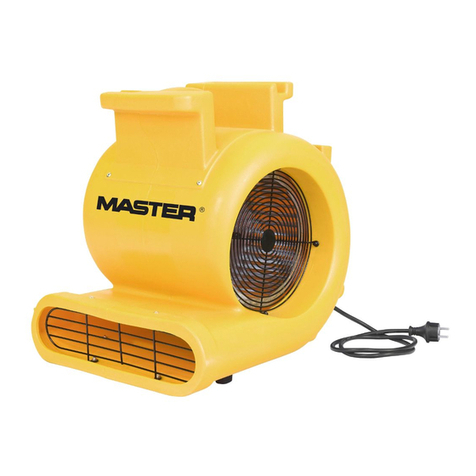
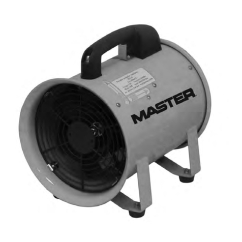
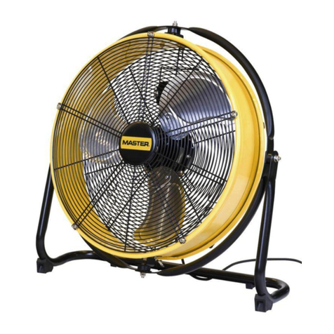
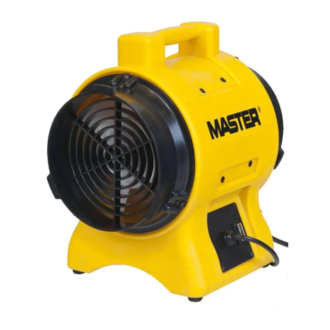
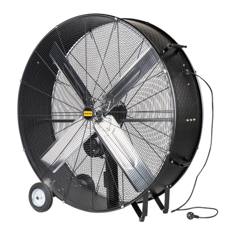
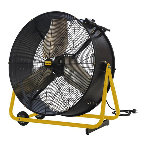
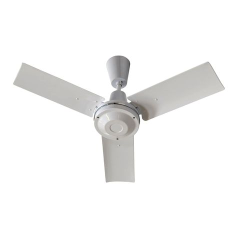
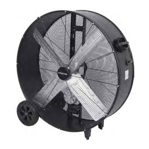
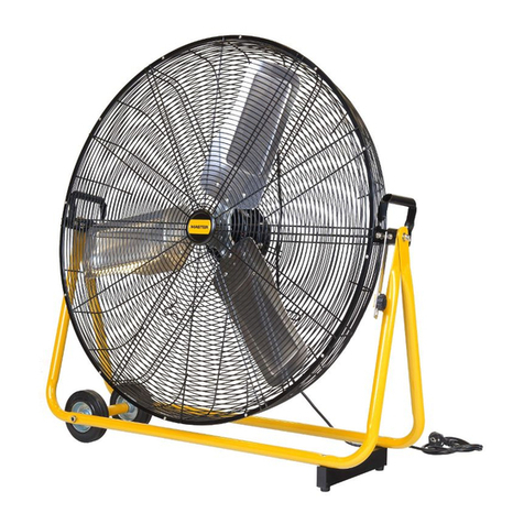
Master E36202 Manual

E36202 - E48202
E56002 - E60002
IT
ITITITITDK
NL
FR
ES
DE
GB
EE
LV
LT
HR
SE
BG
SK
SI
HU
CZ
RU
NO
FI
RO
PL
USER AND MAINTENANCE BOOK
en
LIBRETTO USO E MANUTENZIONE
it
BEDIENUNGS- UND WARTUNGSANLEITUNG
de
MANUAL DE INSTRUCCIONES PARA EL USO Y MANTENIMIENTO
es
MANUEL D’UTILISATION ET DE MAINTENANCE
fr
HANDLEIDING VOOR GEBRUIK EN ONDERHOUD
nl
MANUAL DE USO E MANUTENÇÃO
pt
VEJLEDNING OM BRUG OG VEDLIGEHOLDELSE
da
KÄYTTÖ- JA HUOLTO-OHJE
HEFTE FOR BRUK OG VEDLIKEHOLD
no
ANVÄNDAR- OCH UNDERHÅLLSHANDBOK
sv
INSTRUKCJA OBSŁUGI I KONSERWACJI
pl
РУКОВОДСТВО ПО ЭКСПЛУАТАЦИИ И ТЕХНИЧЕСКОМУ ОБСЛУЖИВАНИЮ
ru
PŘÍRUČKA PRO POUŽITÍ A ÚDRŽBU
cs
HASZNÁLATI ÉS KARBANTARTÁSI KÉZIKÖNYV
hu
PRIROČNIK Z NAVODILI ZA UPORABO IN VZDRŽEVANJE
sl
KNJIŽICA O UPORABI I ODRŽAVANJU
hr
NAUDOJIMO IR PRIEŽIŪROS KNYGELĖ
lt
LIETOŠANAS UN TEHNISKĀS APKOPES GRĀMATIŅA
lv
KASUTUS- JA HOOLDUSJUHEND
et
LIVRET DE UTILIZARE ŞI ÎNTREŢINERE
ro
PRÍRUČKA PRE POUŽITIE A ÚDRŽBU
sk
НАРЪЧНИК ЗА ИЗПОЛЗВАНЕ И ПОДДРЪЖКА
bg
使用和维护手册
zh
ПАЙДАЛАНУ ЖӘНЕ ТЕХНИКАЛЫҚ ҚЫЗМЕТ КӨРСЕТУ ЖЕТЕКШІЛІГІ
kk

Printed in Thailand Part No.10083789
1
ASSEMBLY INSTRUCTIONS & PARTS MANUAL FOR
MODEL: 36202, 48202, 56202, 60002
READ INSTRUCTIONS CAREFULLY BEFORE ATTEMPTING TO ASSEMBLE OR SERVICE THE HUSAN CEILING
FAN. FAILURE TO COMPLY WITH INSTRUCTIONS COULD RESULT IN PERSONAL INJURY AND/OR PROPERTY
DAMAGE.
RETAIN FOR FUTURE REFERENCE.
READ AND SAVE THESE INSTRUCTIONS
A statement that the installation is to be in accordance with the
National Electric Code and local code.
General Safety Information
WARNING: DISCONNECT POWER BEFORE INSTALLING OR
SERVICING THIS EQUIPMENT.
1. All electrical wiring should be done by a qualified electrician in
accordance with applicable Nation Electrical Codes.
2. Do not allow moving blades to come in contact with any part of
the body.
3. Mount fan so that fan blades are 3 meters or higher form floor.
4. Make sure hanger hooks are mounted securely to structural
ceiling members.
5. Do not mount in an area which will allow the fan to get wet.
WARNING: DO NOT USE IN AN EXPLOSIVE ATMOSPHERE.
6. Make certain that the ground wire is connected to the ground
terminal and to a suitable electrical ground.
NOTE: when mounted in cathedral ceilings, the blade tip should be
at least 12 inches from the angle roof line to prevent air “blow
back” causing possible fan sway.
CAUTION: Read and follow instructions carefully, Failure to
comply with instructions could result in the risk of fire,
electric shock and injury to persons.
WARNING: TO REDUCE THE RISK OF PERSONAL INJURY DO
NOT BEND THE BLADE BRACKETS WHEN INSTALLING THE
BRACKETS OR CLEANING THE FAN. DO NOT INSERT
FOREIGN OBJECT IN BETWEEN ROTATING FAN BLADES.
Description
The Master Industrial ceiling Fans are designed as a dual purpose
product. By minimizing temperature stratification in winter, they can
reduce heating costs in high bay buildings. The summertime
application provides a gentle downward movement of air for general
air re circulation and evaporative cooling. A permanent split capacitor
motor and permanently lubricated sealed ball bearings add to the
efficiency and quietness of the fans.
Unpacking
1. Remove fan components from carton carefully.
2. Check for shipping damage.
3. Check for any missing parts against parts list.
RECOMMENDED MOUNTING HEIGHTS.
For heat reclamation, this fan should be mounted on the standard
50mm. downrod included. On installations through drop ceiling,
note the diameter of the downrod hole in ceiling should be 60mm.
CAUTION: Fan blades should not be mounted lower than 3
meters above the floor.
SPECIFICATIONS
MODEL
NUMBER
36202
48202
56002
60002
BLADE
SWEEP
900
1200
1400
1500
COLOR
WHITE
WHITE
WHITE
WHITE
MAX
HZ
50/60
50/60
50/60
50/60
MAX
RPM
325
300
290
300
AMPS
0.31
0.53
0.55
0.60
VO LTAG E
230
230
230
230
WT
(KGS)
8
10
10
13
WATT
71
105
110
120
INDUSTRIAL CEILING FANS
CEILING FANS SHOULD BE INSTALLED
BY QUALIFIED INSTALLER.
MASTER

Printed in Thailand
2
Assembly
This fan includes a ”secondary support ”safety cable feature that
complies with existing National Safety requirements and all other
proposed safety regulations for overhead air movement
equipment. To insure proper installation of this important
safety feature, please read and follow these instructions carefully
1. Carefully unwrap the coiled safety cable and motor lead wires.
2. At the motor yoke assembly (A), remove the cotter pin and loosen
the hexagon nut. Carefully remove spring washer and the hexagon
screw (E) (See Figure 1)
3. Slide the upper canopy cover (B) (Bell shaped) up the rod. Slide the
lower canopy cover (C) up the rod.
4. Feed the three wires and the safety cable through the center hole in
the steel yoke connecting piece above the motor (A) and then
continue feeding wires and cable through the downrod until the
Wires and cable come out at the upper (shackle) end.
5. Mount the downrod to the yoke (A) and replace the hexagon screw.
Secure the spring washer hexagon nut and spread the cotter pin.
NOTICE: The safety cable should be taped to one side of the yoke
with electrical tape to prevent the cable from resting on top of motor
during running operation (See Figure 2)
6. Slide the lower canopy (C)to be a 1/4” minimum height above
motor.
CAUTION: Do not allow the permanently installed lower canopy
to tough the revolving motor as damage will occur. Make sure all
wires are securely places to avoid rubbing against the motor.
7. Attach the three blades, curved side down to the motor with the
insulation pad mounted between the blade and the motor. Make
sure blade holder is flat against motor platform when tightening
Blade nuts for secure fit.
CAUTION: Blade must be fastened to the motor as shown in Figure
1. DO NOT reverse blade when installing.
NOTE: Blades are weight balance per set. DO NOT mix on multiple
fan installations.
NOTE: Do not bend fan blade brackets.
WARNING: DISCONNECT CIRCUIT POWER BEFORE MAKING
ANY ELECTRICAL CONNECTIONS.
WARNING: To reduce the risk of fire, electric shock, or personal
injury,mount directly to a structural framing member or to an outlet
box marked acceptable for fan support of 15 kg (35lbs) or less. For
outlet box mounting, use mounting screws provided with the outlet
box
8. Before attaching the appropriate “J” hook to the building structure
member note the following:
IMPORTANT: WHEN MOUNTING THIS FAN, THE
SUPPORT BEAM MUST BE SUITABLE FOR A 110 KGS LOAD
LIMIT.
CAUTION: If pilot hole is used with the wood thread hook, the
pilot hole should be drilled no larger than the minor diameter of
the screw thread on the hook. Do not put a lubricant on the “J”
hook. At least 1 1/2” of the screw threads should be secure into
the structural wood joist. When the threaded bolt hook is used,
be careful to secure tightly with supplied lock-washers and
nuts. Attach the hook as instructed and hang the fan.
CAUTION: Make sure that blades are attached as shown.
9. This fan is equipped with the required “secondary support” cable.
This cable must be affixed to the beam structures and securely
clamped in such manner to support the weight of the fan in event
The mounting hook or other parts fail. After wrapping cable around
A structural member that will support 300 lbs,. Secure cable with
supplied cable clamps as illustrated in Figure 3.(Note: Any
Additional materials needed for specific installations may be
purchased from your local distributor.)
NOTICE: Leave approximately 75mm but no more than 125mm.
of total slack on this safety cable to allow for possible fan
movement. Do not exceed more than 125mm. total slack.
IMPORTANT CAUTION: The safety cable must not be place
between the rubber roller and hook but as illustrated in
Figure 3.
Figure 1.
Part No.10083789
(A) Motor Yoke
Assembly
Steel Yoke
Capacitor
Plastic Pad
Motor Housing
Blade
Hex Bolt
Lock Washer
(B) Upper Canopy
(F) Set Screw
(D) Upper Shackle Assembly
(C) Lower Canopy
(E) Mounting Hex Bolt Set
Wire
Hook
Rubber Roller
Wood Joist
Metal Beam
CAUTION:Leave 6mm.
clearance between lower
canopy and motor housing
CAUTION:Leave 6mm.
clearance between Upper
canopy and ceiling

Printed in Thailand
3
Figure 4
Figure 5
Figure 3
Figure 2
Safety Cable
Safety Cable
Rubber
Roller
Wire Hook
IMPORTANT NOTICE: It is important to note the proper installation
position of the cable clamps as illustrated in Figure 4. To obtain
maximum holding power, install U-bolt section of clip on dead or short
end of cable and saddle on long end of cable, Improper installation
reduces the efficiency of the connection by as much as 40 percent.
10. When hanging fan on factory supplied “J” hook make sure cable
at top of rod is positioned behind “J” hook as illustrated in Figure 3.
WARNING: DISCONNECT CIRCUIT POWER BEFORE MAKING
ANY ELECTRICAL CONNECTIONS.
11.Run the wires from the downrod assembly to the electrical supply
using appropriate wiring in accordance with the local code.
Connect with listed wire connectors available from your local
distributor. Connect back to black, white to white, and green
grounding lead to the grounded connector of the supply circuit.
No loose strands or loose connections should be present. After
splices are made, the wire should be spread apart so that the
green and white are on one side of the outlet box and the black is
on
the other side. Turn splices upward and carefully push all wiring in
to the outlet box.
12.Slide the upper canopy (B) up the rod to within 5mm. of the
ceiling or beam and securely tighten the set screw (F).
13. If a remote control is to be used refer to the installation included
with that control for proper installation and wiring.
14. Restore power.
15. After completing installation, test run in normal operating manner.
Inspect for any possible shake or wobble which may be cause by
binding as result of “tight cable”. If this should happen, shut off
power supply and re-check instructions to correct problem.
NOTE: When any solid state motor speed control is used, a humming
noise will be present in the fan on low speed. This hum is no way
affect operation of the fan and acceptable in most industrial
installations.
Maintenance
WARNING: THESE FAN HAS AN INTERNAL SELF RESETTING
THERMAL OVERLOAD PROTECTOR. ALWAY DISCONNECT
FROM POWER SUPPLY BEFORE SERVICING.
CLEANING
This fan may be wipe off with a damp cloth. Do not allow the motor to
get wet. Do not use solvents or harsh detergent.
CAUTION: Before servicing or cleaning unit, switch power off at
service panel and lock service disconnecting means to prevent
power from being switched on accidentally. When the service
disconnecting means cannot be locked, securely fasten a
prominent warning device, such as a tag, to the service panel.
LUBRICATION
All bearings are permanently lubricated and require no further
lubrication.
WHITE
BLACK
BLACK
BLACK
WHITE/BLACK
OPTIONAL
SOLID STATE
REGULATOR
MOTOR
GRD.
GRD.
Part No.10083789

4
Printed in Thailand
Y
( ) Included in Motor Assembly.
( ) Standard hardware item, available locally
*
( ) Replacement set of 3 only, white in color.
HOW TO ORDER REPAIR PARTS
In order to obtain any needed repair or replacement parts,
warranty service or technical information, please contact your local
distributor When ordering repair parts, always give the information
listed as follows:
1. The Part Number
2. The Model Number
3. The Part Description
4. Date of Manufacture
Part No.10083789
1
1A
8
11
4
6
11
15
17
19
20
18
22
23
16
5
2
9
10
12
7
14
13
21
6
3
189000380 1
1A 89000199 1
289000168 1
389000106 1
489000205 1
589000182 1
689000397 1
789000403 2
889000366 1
989000021 1
10 89000151 1
11
"J" Hook mounting bolt assy.
Wood screw hook assy
Upper Shackle
Rubber roller
Clevis pin
3/32 x 3/4" Cotter pin
1/4 x 11/2" Hex bolt assy.
1/4 x 11/8" Hex bolt assy.
24" Downrod pipe
Upper canopy, bell shaped
Lower canopy
10-24 x 3/8" canopy set screw 89000212 2
12 Steel Yoke 89000137 1
13 Capacitor clamp screw 89000229 1
14 1
1
1
15 Grounding screw assembly 89000410 1
16 Plastic cable clamp assembly 89000359 1
†800mm. Blade 890004703
†1500mm.Blade 89000496
18 89000267 3
89000274 3
19 89000236 6
20
Blade pad 36" 48" 56"
Blade pad 60"
M 6 x 1 x 10 mm Blade screw
1/4" Blade lock washer 89000144 6
21 Motor Assy 36202 89000571 1
Motor Assy 48202 89000595 1
Motor Assy 56002 89000601 1
Motor Assy 60002 89000618 1
22 Safety cable assembly 89000281 1
23 Cable clamps 89000649 1
Ref. Part
Description No.No. Qty.
Ref. Part
No. Description No. Qty.
Capacitor 36202
Capacitor 48202
Capacitor 56002
Capacitor 60002
89000045
89000083
89000090
89000014
1
17
†1200mm. Blade
†1400mm.Blade
89000471
89000472
Replacement Parts

EN LOS MODELOS 36202 Y 48202 LAS ASPAS DEL VENTILADOR
NO DEBEN ESTAR A MENOS DE 3 METROS DEL SUELO Y EN LOS
MODELOS 56002 Y 60002 A MENOS DE 4 METROS DEL SUELO.

ATENCI
Ó
N
Solicite nuestro Reguladores de velocidad, para
controlar la velocidad de giro del Ventilador,desde
cero hasta el máximo.Son también interruptor ON/OFF


LISTA DE RECAMBIOS
/
17A/17B/17C
14/14A/14B/14C
A

Printed in Thailand Part No.10083789
1
ASSEMBLY INSTRUCTIONS & PARTS MANUAL FOR
MODEL: 36202, 48202, 56202, 60002
READ INSTRUCTIONS CAREFULLY BEFORE ATTEMPTING TO ASSEMBLE OR SERVICE THE HUSAN CEILING
FAN. FAILURE TO COMPLY WITH INSTRUCTIONS COULD RESULT IN PERSONAL INJURY AND/OR PROPERTY
DAMAGE.
RETAIN FOR FUTURE REFERENCE.
READ AND SAVE THESE INSTRUCTIONS
A statement that the installation is to be in accordance with the
National Electric Code and local code.
General Safety Information
WARNING: DISCONNECT POWER BEFORE INSTALLING OR
SERVICING THIS EQUIPMENT.
1. All electrical wiring should be done by a qualified electrician in
accordance with applicable Nation Electrical Codes.
2. Do not allow moving blades to come in contact with any part of
the body.
3. Mount fan so that fan blades are 3 meters or higher form floor.
4. Make sure hanger hooks are mounted securely to structural
ceiling members.
5. Do not mount in an area which will allow the fan to get wet.
WARNING: DO NOT USE IN AN EXPLOSIVE ATMOSPHERE.
6. Make certain that the ground wire is connected to the ground
terminal and to a suitable electrical ground.
NOTE: when mounted in cathedral ceilings, the blade tip should be
at least 12 inches from the angle roof line to prevent air “blow
back” causing possible fan sway.
CAUTION: Read and follow instructions carefully, Failure to
comply with instructions could result in the risk of fire,
electric shock and injury to persons.
WARNING: TO REDUCE THE RISK OF PERSONAL INJURY DO
NOT BEND THE BLADE BRACKETS WHEN INSTALLING THE
BRACKETS OR CLEANING THE FAN. DO NOT INSERT
FOREIGN OBJECT IN BETWEEN ROTATING FAN BLADES.
Description
The Master Industrial ceiling Fans are designed as a dual purpose
product. By minimizing temperature stratification in winter, they can
reduce heating costs in high bay buildings. The summertime
application provides a gentle downward movement of air for general
air re circulation and evaporative cooling. A permanent split capacitor
motor and permanently lubricated sealed ball bearings add to the
efficiency and quietness of the fans.
Unpacking
1. Remove fan components from carton carefully.
2. Check for shipping damage.
3. Check for any missing parts against parts list.
RECOMMENDED MOUNTING HEIGHTS.
For heat reclamation, this fan should be mounted on the standard
50mm. downrod included. On installations through drop ceiling,
note the diameter of the downrod hole in ceiling should be 60mm.
CAUTION: Fan blades should not be mounted lower than 3
meters above the floor.
SPECIFICATIONS
MODEL
NUMBER
36202
48202
56002
60002
BLADE
SWEEP
900
1200
1400
1500
COLOR
WHITE
WHITE
WHITE
WHITE
MAX
HZ
50/60
50/60
50/60
50/60
MAX
RPM
325
300
290
300
AMPS
0.31
0.53
0.55
0.60
VO LTAG E
230
230
230
230
WT
(KGS)
8
10
10
13
WATT
71
105
110
120
INDUSTRIAL CEILING FANS
CEILING FANS SHOULD BE INSTALLED
BY QUALIFIED INSTALLER.
PRZEMYSŁOWE DESTRYFIKATORY SUFITOWE
Uwaga: wentylatory powinny być instalowane
przez profesjonalnego instalatora
ZANIM PRZYSTĄPISZ DO MONTAŻU ALBO SERWISOWANIA URZĄDZENIA PRZECZYTAJ
INSTRUKCJĘ UWAZNIE I STOSUJ SIĘ DO WSKAZÓWEK W NIEJ ZAWARTYCH. NIEDOSTOSOWANIE
SIĘ DO INSTRUKCJI MOŻE SPOWODOWAĆ USZKODZENIA CIAŁA LUB URZĄDZENIA.
ZACHOWAJ INSTRUKCJĘ DO PRZYSZŁYCH
CZYNOŚCI.
PRZECZYTAJ I ZACHOWAJ TĘ INSTRUKCJĘ
Instalacja powinna być zgodna lokalnymi kodami
dotyczącymi instalacji elektrycznych.
INFORMACJE O BEZPIECZEŃSTWIE
OSTRZEŻENIE: WYŁĄCZ ZASILANIE ZANIM
ZACZNIESZ SERWISOWAĆ URZĄDZENIE.
1. Wszystkie instalacje elektryczne powinne być wy-
konane przez profesjonalnych elektryków
2. Nie wolno przesuwać łopatek wentylatora
3. Wentylator powinien być zamontowany 3 metry
od podłogi
4. Upewnij się, że haki są pewnie zamontowane w
strukturze sutu
5. Nie wolno montować wentylatora w obszarze,
gdzie może mieć kontakt z wilgocią
OSTRZEŻENIE: NIE UŻYWAĆ
W TEMPERATURZE WYBUCHOWEJ
6. Upewnij się, że przewód uziemiający jest podłą-
czony do uziemienia i do odpowiedniego uziemie-
nia elektrycznego.
UWAGA: jeśli urządzenie montowane jest na sucie
katedry, ostrze łopatki powinno być co najmniej 12
cali od kąta dachu, żeby zapobiegać podmuchom
wstecznym, spowodowanym pracą wentylatora.
UWAGA: Przeczytaj poniższą instrukcję uważnie
i podążaj zgodnie z jej wskazówkami, aby
uniknąć ryzyka pożaru, porażenia elektrycznego
czy uszkodzenia ciała.
OSTRZEŻENIE: ABY ZREDUKOWAĆ
NIEBEZPIECZEŃSTWO USZKODZENIA
CIAŁA NALEŻY NIE ZAGINAĆ WSPORNIKÓW
PODCZAS INSTALACJI ALBO CZYSZCZENIA.
NIE WKŁADAJ OBCYCH OBJEKTÓW POMIĘDZY
OBRACAJĄCE SIĘ ŁOPATKI WENTYLATORA.
Opis
Destrykatory Master są zaprojektowane jako
produkt podwójnego przeznaczenia. Poprzez
zminimalizowanie różnicy temperatur zimą, potraą
zredukować koszty ogrzewania w wysokich
budynkach. Urządzenie używane latem zapewnia
delikatną cyrkulację powietrza i chłodzenie
ewaporacyjne.
Wypakowanie
1. Wyłóż części wentylatora delikatnie opakowania
2. Sprawdź pod kątem uszkodzenia podczas trans-
portu.
3. Sprawdź pod kątem brakujących części zgodnie
z zawartą listą.
REKOMENDOWANA WYSOKOŚĆ
ZAWIESZENIA
Żeby odzyskiwać ciepło, destrykator powinien być
zamontowany na standardowych 50 mm. wliczając
pręt. Jeśli instalowany jest na sucie podwieszanym,
pamiętaj, że średnica otworu na pręt powinna mieć
60 mm.
UWAGA: Łopatki wentylatora powinny być
montowane wyżej niż 3 metry od podłogi.
Instalacja
Destrykator posiada „podwójne zabezpieczenie”,
czyli przewód bezpieczeństwa zgodny z regulacjami
bezpieczeństwa dla napowietrznych urządzeń.
Żeby zapewnić jego odpowiednią instalację należy
podążać za poniższymi instrukcjami:
1. Ostrożnie rozpakować przewód bezpieczeństwa
oraz przewody silnika.
2. Na jarzmie silnika (A) usuń zawleczkę i rozluźnij
sześciokątną nakrętkę. Ostrożnie usuń podkładkę
sprężynująca i śrubę sześciokątną
3. Przesuń górny daszek obudowy (B) w górę pręta
oraz przesuń dolny daszek (C) obudowy w górę.
4. Doprowadź 3 przewody i przewód bezpieczeń-
stwa przez centralny otwór w stalowym jarzmie
łączącym część nad silnikiem (A), a potem kon-
tynuuj przeciąganie kabli przez dolny pręt, dopóki
przewody nie pojawią się na górnym zakończeniu.
5. Zamontuj pręt do jarzma (A) i zamień szcześcio-
kątną śrubę. Zabezpiecz podkładkę sprężynującą
podkładką szcześciokątną i rozszerz zawleczkę.
UWAGA: Upewnij się, że wszystkie przewody
są bezpiecznie umieszczone w niższym daszku
obudowy.
6. Przesuń niższy daszek obudowy (C) do ¼” mini-
malna odległość powyżej silnika.
UWAGA: Łopatki są ustawione w sposób
balansujących ich wagę, prosimy nie zmieniać
ustawień wentylatora i jego łopatek.
UWAGA: Nie zaginać łopatek wentylatora.
OSTRZEŻENIE: Aby zredukować ryzyko pożaru,
porażenia elektrycznego czy uszkodzenia ciała,
zamontuj bezpośrednio do szkieletu urządzenia
lub do wyjścia puszki (15 kg albo mniej). Żeby
zamontować do puszki należy użyć śrub
zapewnionych w komplecie puszki.
7. Zanim dołączysz odpowiedni haczyk „J” pa-
miętaj o poniższym:
WAŻNE: BELKA NA KTÓREJ ZAMONTOWANY
ZOSTANIE DESTRYFIKATOR MUSI BYĆ W
STANIE UDŹWIGNĄĆ 110 KG.
UWAGA: jeśli otwór prowadnicy jest używany z
gwintem drewnianego haka, to otwór prowadnicy
nie może być większy od mniejszej średnicy
śruby na haku. Nie używaj lubrykantu na haku
„J”. ½” gwinta śruby powinno być zabezpieczone
w belce stropowej. Jeśli używana jest śruba
gwintowana, pamiętaj żeby zabezpieczyć
szczelnie wraz z załączonymi podkładkami
blokującymi i nakrętkami.
UWAGA: Upewnij się, że łopatki są ustawione
tak jak to pokazano.
8. Destrykator jest wyposażony w podwójnie za-
bezpieczający przewód. Przewód musi być przy-
mocowany do struktury belki i zabezpieczony
zaciskami. Po owinięciu przewodu wokół elemen-
tów, zabezpiecz go za pomocą załączonych zaci-
sków jak na ilustracji nr 3.
UWAGA: żadne dodatkowe materiały nie są
potrzebne do instalacji. Dla utrudnionych
instalacji dodatkowe urządzenia mogą zostać
zakupione u lokalnego dystrybutora.
UWAGA: pozostaw około 75 mm, ale nie więcej niż
125 mm zwisu na przewodzie zabezpieczającym,
żeby umożliwić ruch wentylatora.
Rysunek 1.

WAŻNA UWAGA: Kabel zabezpieczający nie
może być umiejscowiony pomiędzy gumowe
łożysko a hak. Rys 3.
9. Upewnij się, że kabel na samej górze pręta jest
umieszczony jak na rysunku:
WAŻNA UWAGA: Odpowiednia pozycja
zainstalowania zacisków przewodu
przedstawiona jest na rysunku 4. Aby uzyskać
maksymalną siłę utrzymania, zainstaluj część U -
śruby zacisku na krótkim końcu przewodu i osadź
na długim końcu przewodu. Nieodpowiednia
instalacja redukuje wydajność połączenia o 40%.
OSTRZEŻENIE: ROZŁĄCZ ZASILANIE OBWODU
ZANIM PRZYSTĄPISZ DO JAKICHKOLWIEK
PODŁĄCZEŃ ELEKTRYCZNYCH
10. Podłącz przewody od dolnego pręta do zasilania
elektrycznego używając konektorów w następują-
cy sposób: czarny przewód do czarnego, biały do
białego, zielony uziemiający do uziemiającego ko-
nektora zasilania elektrycznego. Nie powinno być
żadnych luźnych kabli oraz konektorów. Po połą-
czeniu, przewód powinien być rozszerzony tak,
żeby zielony i biały były bo jednej stronie puszki, a
czarny po drugiej. Odwróć podłączenie i ostrożnie
przesuń wszystkie przewody do puszki.
11. Przesuń górny daszek obudowy (B) w górę prę-
ta do 5mm od sutu albo belki i ostrożnie zaciśnij
zestaw śrub (F).
12. Sterownik powinien zostać zainstalowany zgod-
nie z załączonym rysunkiem.
13. Przywróć zasilanie.
14. Po kompletnej instalacji, przetestuj włączając
normalny tryb pracy. Sprawdź pod względem
wstrząsów, które mogą być wywołane przez wią-
zanie przewodów. Jeśli wystąpiła powyższa sy-
tuacja, należy wyłączyć zasilanie i sprawdzić w
instrukcji ponownie jak prawidłowo zainstalować
urządzenie.
UWAGA: jeśli nie jest używany żaden regulator
prędkości silnika, odczuwalny hałas będzie słyszany
podczas niskich obrotów wentylatora. Odgłos ten
jest nieunikniony i akceptowalny w większości
instalacji przemysłowych.
Utrzymanie
OSTRZEŻENIE: DESTRYFIKATORY MAJĄ
WEWNĘTRZNE, SAMORESETUJĄCE SIĘ
ZABEZPIECZENIE TERMICZNE. PAMIĘTAJ
ZAWSZE ODŁĄCZAĆ URZĄDZENIE OD
ZASILANIA ZANIM PRZYSTĄPISZ DO
CZYNNOŚCI SERWISOWYCH.
Smarowanie
Wszystkie łożyska są nasmarowane na stałe i nie
potrzebują żadnej, dodatkowej konserwacji.
Czyszczenie
Destrykator może być czyszczony ścierką lub
wilgotną tkaniną. Nie pozwól, aby woda dostała się
do silnika. Nie używaj środków do czyszczenia, ani
detergentów.
UWAGA: Zanim przystąpisz do czynności
serwisowych, albo czyszczenia produktu, wyłącz
zasilanie, oraz do dopilnuj, żeby nie zostało
włączone przypadkowo, podczas Twojej pracy.
Printed in Thailand
3
Figure 4
Figure 5
Figure 3
Figure 2
Safety Cable
Safety Cable
Rubber
Roller
Wire
Hook
IMPORTANT NOTICE: It is important to note the proper installation
position of the cable clamps as illustrated in Figure 4. To obtain
maximum holding power, install U-bolt section of clip on dead or short
end of cable and saddle on long end of cable, Improper installation
reduces the efficiency of the connection by as much as 40 percent.
10. When hanging fan on factory supplied “J” hook make sure cable
at top of rod is positioned behind “J” hook as illustrated in Figure 3.
WARNING: DISCONNECT CIRCUIT POWER BEFORE MAKING
ANY ELECTRICAL CONNECTIONS.
11.Run the wires from the downrod assembly to the electrical supply
using appropriate wiring in accordance with the local code.
Connect with listed wire connectors available from your local
distributor. Connect back to black, white to white, and green
grounding lead to the grounded connector of the supply circuit.
No loose strands or loose connections should be present. After
splices are made, the wire should be spread apart so that the
green and white are on one side of the outlet box and the black is
on
the other side. Turn splices upward and carefully push all wiring in
to the outlet box.
12.Slide the upper canopy (B) up the rod to within 5mm. of the
ceiling or beam and securely tighten the set screw (F).
13. If a remote control is to be used refer to the installation included
with that control for proper installation and wiring.
14. Restore power.
15. After completing installation, test run in normal operating manner.
Inspect for any possible shake or wobble which may be cause by
binding as result of “tight cable”. If this should happen, shut off
power supply and re-check instructions to correct problem.
NOTE: When any solid state motor speed control is used, a humming
noise will be present in the fan on low speed. This hum is no way
affect operation of the fan and acceptable in most industrial
installations.
Maintenance
WARNING: THESE FAN HAS AN INTERNAL SELF RESETTING
THERMAL OVERLOAD PROTECTOR. ALWAY DISCONNECT
FROM POWER SUPPLY BEFORE SERVICING.
CLEANING
This fan may be wipe off with a damp cloth. Do not allow the motor to
get wet. Do not use solvents or harsh detergent.
CAUTION: Before servicing or cleaning unit, switch power off at
service panel and lock service disconnecting means to prevent
power from being switched on accidentally. When the service
disconnecting means cannot be locked, securely fasten a
prominent warning device, such as a tag, to the service panel.
LUBRICATION
All bearings are permanently lubricated and require no further
lubrication.
WHITE
BLACK
BLACK
BLACK
WHITE/BLACK
OPTIONAL
SOLID STATE
REGULATOR
MOTOR
GRD.
GRD.
Part No.10083789
Rysunek 2 i 3.
Printed in Thailand
3
Figure 4
Figure 5
Figure 3
Figure 2
Safety Cable
Safety Cable
Rubber
Roller
Wire Hook
IMPORTANT NOTICE: It is important to note the proper installation
position of the cable clamps as illustrated in Figure 4. To obtain
maximum holding power, install U-bolt section of clip on dead or short
end of cable and saddle on long end of cable, Improper installation
reduces the efficiency of the connection by as much as 40 percent.
10. When hanging fan on factory supplied “J” hook make sure cable
at top of rod is positioned behind “J” hook as illustrated in Figure 3.
WARNING: DISCONNECT CIRCUIT POWER BEFORE MAKING
ANY ELECTRICAL CONNECTIONS.
11.Run the wires from the downrod assembly to the electrical supply
using appropriate wiring in accordance with the local code.
Connect with listed wire connectors available from your local
distributor. Connect back to black, white to white, and green
grounding lead to the grounded connector of the supply circuit.
No loose strands or loose connections should be present. After
splices are made, the wire should be spread apart so that the
green and white are on one side of the outlet box and the black is
on
the other side. Turn splices upward and carefully push all wiring in
to the outlet box.
12.Slide the upper canopy (B) up the rod to within 5mm. of the
ceiling or beam and securely tighten the set screw (F).
13. If a remote control is to be used refer to the installation included
with that control for proper installation and wiring.
14. Restore power.
15. After completing installation, test run in normal operating manner.
Inspect for any possible shake or wobble which may be cause by
binding as result of “tight cable”. If this should happen, shut off
power supply and re-check instructions to correct problem.
NOTE: When any solid state motor speed control is used, a humming
noise will be present in the fan on low speed. This hum is no way
affect operation of the fan and acceptable in most industrial
installations.
Maintenance
WARNING: THESE FAN HAS AN INTERNAL SELF RESETTING
THERMAL OVERLOAD PROTECTOR. ALWAY DISCONNECT
FROM POWER SUPPLY BEFORE SERVICING.
CLEANING
This fan may be wipe off with a damp cloth. Do not allow the motor to
get wet. Do not use solvents or harsh detergent.
CAUTION: Before servicing or cleaning unit, switch power off at
service panel and lock service disconnecting means to prevent
power from being switched on accidentally. When the service
disconnecting means cannot be locked, securely fasten a
prominent warning device, such as a tag, to the service panel.
LUBRICATION
All bearings are permanently lubricated and require no further
lubrication.
WHITE
BLACK
BLACK
BLACK
WHITE/BLACK
OPTIONAL
SOLID STATE
REGULATOR
MOTOR
GRD.
GRD.
Part No.10083789
Rysunek 4.
Printed in Thailand
3
Figure 4
Figure 5
Figure 3
Figure 2
Safety Cable
Safety Cable
Rubber
Roller
Wire Hook
IMPORTANT NOTICE: It is important to note the proper installation
position of the cable clamps as illustrated in Figure 4. To obtain
maximum holding power, install U-bolt section of clip on dead or short
end of cable and saddle on long end of cable, Improper installation
reduces the efficiency of the connection by as much as 40 percent.
10. When hanging fan on factory supplied “J” hook make sure cable
at top of rod is positioned behind “J” hook as illustrated in Figure 3.
WARNING: DISCONNECT CIRCUIT POWER BEFORE MAKING
ANY ELECTRICAL CONNECTIONS.
11.Run the wires from the downrod assembly to the electrical supply
using appropriate wiring in accordance with the local code.
Connect with listed wire connectors available from your local
distributor. Connect back to black, white to white, and green
grounding lead to the grounded connector of the supply circuit.
No loose strands or loose connections should be present. After
splices are made, the wire should be spread apart so that the
green and white are on one side of the outlet box and the black is
on
the other side. Turn splices upward and carefully push all wiring in
to the outlet box.
12.Slide the upper canopy (B) up the rod to within 5mm. of the
ceiling or beam and securely tighten the set screw (F).
13. If a remote control is to be used refer to the installation included
with that control for proper installation and wiring.
14. Restore power.
15. After completing installation, test run in normal operating manner.
Inspect for any possible shake or wobble which may be cause by
binding as result of “tight cable”. If this should happen, shut off
power supply and re-check instructions to correct problem.
NOTE: When any solid state motor speed control is used, a humming
noise will be present in the fan on low speed. This hum is no way
affect operation of the fan and acceptable in most industrial
installations.
Maintenance
WARNING: THESE FAN HAS AN INTERNAL SELF RESETTING
THERMAL OVERLOAD PROTECTOR. ALWAY DISCONNECT
FROM POWER SUPPLY BEFORE SERVICING.
CLEANING
This fan may be wipe off with a damp cloth. Do not allow the motor to
get wet. Do not use solvents or harsh detergent.
CAUTION: Before servicing or cleaning unit, switch power off at
service panel and lock service disconnecting means to prevent
power from being switched on accidentally. When the service
disconnecting means cannot be locked, securely fasten a
prominent warning device, such as a tag, to the service panel.
LUBRICATION
All bearings are permanently lubricated and require no further
lubrication.
WHITE
BLACK
BLACK
BLACK
WHITE/BLACK
OPTIONAL
SOLID STATE
REGULATOR
MOTOR
GRD.
GRD.
Part No.10083789
Rysunek 5.

4
Printed in Thailand
Y
( ) Included in Motor Assembly.
( ) Standard hardware item, available locally
*
( ) Replacement set of 3 only, white in color.
HOW TO ORDER REPAIR PARTS
In order to obtain any needed repair or replacement parts,
warranty service or technical information, please contact your local
distributor When ordering repair parts, always give the information
listed as follows:
1. The Part Number
2. The Model Number
3. The Part Description
4. Date of Manufacture
Part No.10083789
1
1A
8
11
4
6
11
15
17
19
20
18
22
23
16
5
2
9
10
12
7
14
13
21
6
3
189000380 1
1A 89000199 1
289000168 1
389000106 1
489000205 1
589000182 1
689000397 1
789000403 2
889000366 1
989000021 1
10 89000151 1
11
"J" Hook mounting bolt assy.
Wood screw hook assy
Upper Shackle
Rubber roller
Clevis pin
3/32 x 3/4" Cotter pin
1/4 x 11/2" Hex bolt assy.
1/4 x 11/8" Hex bolt assy.
24" Downrod pipe
Upper canopy, bell shaped
Lower canopy
10-24 x 3/8" canopy set screw 89000212 2
12 Steel Yoke 89000137 1
13 Capacitor clamp screw 89000229 1
14 1
1
1
15 Grounding screw assembly 89000410 1
16 Plastic cable clamp assembly 89000359 1
†800mm. Blade 890004703
†1500mm.Blade 89000496
18 89000267 3
89000274 3
19 89000236 6
20
Blade pad 36" 48" 56"
Blade pad 60"
M 6 x 1 x 10 mm Blade screw
1/4" Blade lock washer 89000144 6
21 Motor Assy 36202 89000571 1
Motor Assy 48202 89000595 1
Motor Assy 56002 89000601 1
Motor Assy 60002 89000618 1
22 Safety cable assembly 89000281 1
23 Cable clamps 89000649 1
Ref. Part
Description No.No. Qty.
Ref. Part
No. Description No. Qty.
Capacitor 36202
Capacitor 48202
Capacitor 56002
Capacitor 60002
89000045
89000083
89000090
89000014
1
17
†1200mm. Blade
†1400mm.Blade
89000471
89000472
Replacement Parts
4
Printed in Thailand
Y
( ) Included in Motor Assembly.
( ) Standard hardware item, available locally
*
( ) Replacement set of 3 only, white in color.
HOW TO ORDER REPAIR PARTS
In order to obtain any needed repair or replacement parts,
warranty service or technical information, please contact your local
distributor When ordering repair parts, always give the information
listed as follows:
1. The Part Number
2. The Model Number
3. The Part Description
4. Date of Manufacture
Part No.10083789
1
1A
8
11
4
6
11
15
17
19
20
18
22
23
16
5
2
9
10
12
7
14
13
21
6
3
189000380 1
1A 89000199 1
289000168 1
389000106 1
489000205 1
589000182 1
689000397 1
789000403 2
889000366 1
989000021 1
10 89000151 1
11
"J" Hook mounting bolt assy.
Wood screw hook assy
Upper Shackle
Rubber roller
Clevis pin
3/32 x 3/4" Cotter pin
1/4 x 11/2" Hex bolt assy.
1/4 x 11/8" Hex bolt assy.
24" Downrod pipe
Upper canopy, bell shaped
Lower canopy
10-24 x 3/8" canopy set screw 89000212 2
12 Steel Yoke 89000137 1
13 Capacitor clamp screw 89000229 1
14 1
1
1
15 Grounding screw assembly 89000410 1
16 Plastic cable clamp assembly 89000359 1
†800mm. Blade 890004703
†1500mm.Blade 89000496
18 89000267 3
89000274 3
19 89000236 6
20
Blade pad 36" 48" 56"
Blade pad 60"
M 6 x 1 x 10 mm Blade screw
1/4" Blade lock washer 89000144 6
21 Motor Assy 36202 89000571 1
Motor Assy 48202 89000595 1
Motor Assy 56002 89000601 1
Motor Assy 60002 89000618 1
22 Safety cable assembly 89000281 1
23 Cable clamps 89000649 1
Ref. Part
Description No.No. Qty.
Ref. Part
No. Description No. Qty.
Capacitor 36202
Capacitor 48202
Capacitor 56002
Capacitor 60002
89000045
89000083
89000090
89000014
1
17
†1200mm. Blade
†1400mm.Blade
89000471
89000472
Replacement Parts


NOTE:______________________________________________________________
____________________________________________________________________
____________________________________________________________________
____________________________________________________________________
____________________________________________________________________
____________________________________________________________________
____________________________________________________________________
____________________________________________________________________
____________________________________________________________________
____________________________________________________________________
____________________________________________________________________
____________________________________________________________________
____________________________________________________________________
____________________________________________________________________
____________________________________________________________________
►en - DISPOSAL OF THE PRODUCT
-This product has been designed and manufactured with top-quality materials and components, which can be re-cycled and re-used.
-When a crossed-wheely bin symbol is attached to the product, it means that the product is protected by the, 2002/96/EC European Directive.
-Please obtain information regarding the local dierentiated collection system for electrical and electronic products.
-Respect local Standards in force and do not dispose of old products as normal domestic waste. Correct disposal of the product helps to prevent possible
negative consequences for health, the environment and mankind.
►it - SMALTIMENTO DEL PRODOTTO
-Questo prodotto è stato progettato e fabbricato con materiali e componenti di alta qualità, che possono essere riciclati e riutilizzati.
-Quando ad un prodotto è attaccato il simbolo del bidone con le ruote segnato da una croce, signica che il prodotto è tutelato dalla Direttiva Europea
2002/96/CE.
-Si prega di informarsi in merito al sistema locale di raccolta dierenziata per i prodotti elettrici ed elettronici.
-Rispettare le norme locali in vigore e non smaltire i prodotti vecchi nei normali riuti domestici. Il corretto smaltimento del prodotto aiuta ad evitare pos-
sibili conseguenze negative per la salute dell’ambiente e dell’uomo.
►de - ENTSORGUNG DES PRODUKTS
-Dieses Produkt wurde unter Verwendung von Qualitätsmaterialien und -bauteilen entwickelt und hergestellt, die recycelt und wieder verwendet werden
können.
-Ist ein Produkt gekennzeichnet durch die Mülltonne mit Rädern und einem Kreuz, wird hier angezeigt, dass dieses Produkt durch die europäische
Direktive 2002/96/EG überwacht ist.
-Es wird gebeten, sich über die vor Ort bestehende Mülltrennung bezüglich elektrischer und elektronischer Produkte zu informieren.
-Die vor Ort geltenden Vorschriften zur Müllentsorgung müssen eingehalten werden und alte Produkte dürfen nicht zusammen mit dem Hausmüll
entsorgt werden. Die ordnungsgemäße Entsorgung des Produkts hilft mögliche negative Folgen für Gesundheit und Umwelt zu vermeiden.
►es - ELIMINACIÓN DEL PRODUCTO
-Este producto ha sido diseñado y fabricado con materiales y componentes de alta calidad que se pueden reciclar y reutilizar.
-Cuando en el producto se encuentra el símbolo del contenedor con las ruedas tachado con una cruz, signica que el producto está tutelado por la
Directiva europea 2002/96/CE.
-Se ruega informarse acerca del sistema local de recogida selectiva para los productos eléctricos y electrónicos.
-Respete las normas locales vigentes y no elimine los productos viejos junto con los residuos domésticos normales. La eliminación correcta del producto
ayuda a evitar posibles consecuencias negativas para la salud del ambiente y del hombre.
►pl - UTYLIZACJA PRODUKTU
-Niniejszy produkt został wyprodukowany z najwyższej jakości materiałów, które mogą być poddane recyklingowi i zostać ponownie użyte.
-Symbol przekreślonego kosza na śmieci umieszczony na produkcie oznacza, że ów produkt jest chroniony Dyrektywą Unii Europejskiej 2002/96/WE.
-Należy zapoznać się z lokalnym systemem zbiórki produktów elektronicznych i elektrycznych.
-Stare produkty muszą być usuwane zgdonie z obowiązującymi normami. Odpowiednia utylizacja urządzeń elektrycznych i elektronicznych zapobiega
negatywnym następstwą które mogą mieć wpływ na zdrowie, środowisko i całą ludzkość.

6666.333 Edition 16
MCS Italy S.p.A.
Via Gardesana 11, -37010-
Pastrengo (VR), Italy
MCS Italy S.p.A.
Виа Гардесана 11, 37010
Пастренго (Верона), Италия
MCS Central Europe Sp. z o.o.
ul. Magazynowa 5A,
62-023 Gądki, Poland
MCS Central Europe Sp. z o.o.
ул. Магазинова, 5A,
62-023 Гадки, Польша
MCS Russia LLC
ul. Transportnaya - 22 ownership 2,
142802, STUPINO, Moscow region, Russia
ООО «ЭмСиЭс Россия»
Ул. Транспортная, владение 22/2,
142802, г.Ступино, Московская обл., РФ
MCS China LTD
Unit 2B, 512 Yunchuan Rd.,
Shanghai,
201906, China
MCS China LTD
Юньчуань роад, 512,
строение 2В, Шанхай,
201906, Китай
EURITECSA
C/Calabozos, 6 Polígono Industrial,
28108 Alcobendas (Madrid)
Spain
EURITECSA
Ц/Калабозос, 6 Полигоно Индустриал,
28108 Алкобендас (Мадрит)
Испания
Other manuals for E36202
1
This manual suits for next models
3
Table of contents
Other Master Fan manuals

Master
Master CD 5000 User manual

Master
Master MAC-18W-DDF-A User manual

Master
Master MAC-708-SF Training manual

Master
Master DF 30 P Manual

Master
Master DF 20 P Manual

Master
Master DF 20 P User manual

Master
Master DFX 20 Manual

Master
Master MAC-18WW Quick reference guide

Master
Master DF 30 P Manual

Master
Master E36202 Manual

Master
Master CD 5000 CH User manual

Master
Master MAC-12F Training manual

Master
Master MAC-20F Training manual

Master
Master MAC-30D Training manual

Master
Master CD 5000 User manual

Master
Master DF 20 P User manual

Master
Master BL 4800 User manual

Master
Master FS 60 Manual

Master
Master MF 30 P User manual

Master
Master MAC-24W Training manual