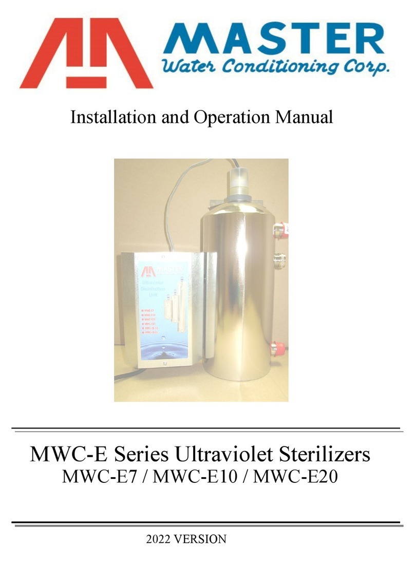
Master MWC Series User manual

MWC-ES Series Ultraviolet Sterilizers
MWC-ES7 / MWC-ES10 / MWC-ES20
Installation and Operation Manual
2022 VERSION

Table of Contents
Page
Topic
Description
1
Model #
Model Number
Caution
Looking at UV Light
Shipping Description
UV Packaging
2
Piping Layout
Piping Layout
Specification Table
Unit Specifications
3
Pre-Treatment
Pre-treatment Discussed
Water Quality Table
Unit Location
Unit Set Up
4
MWC-ES Pressure Vessel
Pressure Vessel Installation
Cont’d
5
Electrical
Electrical Requirements
MWC-ES Power Supply
Power Supply Installation
6
Grounding
Grounding Instructions
7
Quartz and O’ring
Installing Quartz and O’ring
Germicidal Lamp
Installing Germicidal Lamp
MWC-ES Start Up
Start Up Procedure
Water Pressure Test
Filling Vessel with water
8
Disinfecting
Instructions for Disinfecting
the Piping System
Final Check
Installation Final Check
9
Annual Maintenance
Germicidal Lamp
Quartz Sleeve
UV Quartz eye
9000 Hour Timer
Resetting Timer
10
Figure 1
Figure 1
11
Troubleshooting
Troubleshooting
12
Troubleshooting, cont’d
Back
Cover
Warranty
Warranty

1
Installation and Operating Instructions
for MWC-ES Series Ultraviolet Sterilizers
Model #:
_______ MWC-ES7 7 gpm UV -¾”
_______ MWC-ES10 10 gpm UV -¾”
_______ MWC-ES20 20 gpm UV -1”
CAUTION:
NEVER LOOK DIRECTLY AT THE ULTRAVIOLET LIGHT WITH
THE NAKED EYE. View through a piece of ordinary glass or optical
glasses. ULTRAVIOLET LIGHT may cause eye irritation if eye is not
properly protected. You should never have to look directly at the
ULTRAVIOLET LIGHT when installing or trouble-shooting one of our
MWC-E Water Sterilizers.
Shipping Description:
The UV unit is shipped complete as follows:
The large box contains the UV vessel and inside that box you will
also find the following:
1. A box containing the gland nut, quartz o’ring, silicone, and
UV brackets with grounding lug.
2. A box containing the MWC-ES power supply with
grounding wire.
3. A box containing the (1)-¾” SS or (1)- N/C SS normally
closed solenoid.
4. A tube containing the germicidal lamp.
5. A tube containing the quartz sleeve.

2
Pre-Treatment:

3
A complete water test is recommended to determine if pre-treatment
equipment is required before installation of the UV unit. Water must
meet criteria below:
Contaminant
Maximum Allowable Level
Chloride
250 ppm
Color
None
Hardness
8 gpg
Iron
0.3 ppm
Manganese
0.05 ppm
pH
Range between 6 and 8.5
Total Dissolved Solids (TDS)
500 ppm
Turbidity
5 ntu
If untreated water quality exceeds the maximum allowable levels
specified, this will result in bacteria passing through the UV unit
and into the piping system.
Unit Location:
1. The MWC-ES unit must be installed after the well tank and any
water pre-treatment equipment (softeners, filter, etc.). You must
install a Cartridge type Dirt Filter before the MWC-ES unit to
eliminate the possibility of a dirt build-up inside the stainless
steel sterilization chamber. (SEE PAGE 2, PIPING LAYOUT )
2. Install at least 4 feet from a dedicated electrical outlet.
DO NOT INSTALL NEAR ANY HEATING SYSTEMS WHICH
RAISE THE AIR TEMPERATURE OVER 100 DEGREES.
MWC-ES 304 Electro Polished SS Vessel Installation:
1. The ultraviolet unit is designed to be installed in a vertical position.
The unit is supplied with (2) brackets to support the unit.
NOTE: The upper bracket has a grounding lug attached to it.
2. Place the top bracket (larger one) over the nipple located at the

4
top of the vessel. The end of the bracket with the three holes
should be facing up towards the top of the vessel.
3. Tighten the gray PVC ring onto the nipple. This will compress
down onto the top of bracket.
4. Attach the smaller bracket to the bottom of the vessel. The
bracket has a clip type fastener that attaches to the bottom rim of
the vessel. The end of the bracket with the three holes should be
facing down towards the bottom of the vessel.
5. Secure the top bracket to a wall by using three appropriate screws
or fasteners (not provided).
Be sure to leave plenty of clearance above vessel for servicing
the quartz tube and germicidal lamp. (For proper clearance, see
Specification Table on page 2)
6. Secure the bottom bracket to the wall by using three screws or
fasteners (not provided).
7. Use quality unions and ball valves on the inlet and outlet for
servicing the unit. See Page 2for a typical installation piping
layout. If sweat fittings are used, be sure soldering is done in such
a manner as not to allow heat to reach the UV vessel. If Schedule
80 PVC or CPVC is used, make sure to follow the proper primer
and solvent instructions.
8. Pipe the inlet into the bottom nipple of the UV vessel.
9. Install a 1’’ x 3/4” reducing bushing (not provided) into the inlet of
the solenoid valve.
10. Install the ¾” (for the ES7 and ES10 units) or the 1” (for the ES20
units) normally closed solenoid to the outlet on the top
nipple of the UV vessel. Make sure that the solenoid is installed in
the proper direction. See page 2 There is an internal flow
restrictor in the outlet nipple of all units. It is recommended you
install a boiler drain on the inlet piping of the unit. This will
allow for easy draining of the vessel when replacing the UV
quartz.
Electrical Requirements:

5
Always follow all local electrical codes when installing our
water
Treatment equipment.
1. Provide a 115v/60Hz properly grounded a dedicated electrical
outlet. (It’s very important that the polarity be correct)
Avoid using outlets that are switch controlled.
2. Maximum amperage required is 5 amps.
3. Make sure the electrical service provides power 24 hours per day.
We recommend installing a surge protector to protect unit from
power surges, which are not covered by warranty.
!!! DO NOT UNDER ANY CIRCUMSTANCE WIRE THE UV
UNIT TO THE WELL PUMP SWITCH OR WELL PUMP
ELECTRICAL SUPPLY !!!
MWC-ES Power Supply Installation:
1. Choose a wall placement that is dry and clear of all piping and
metal objects, and within 4 feet of the UV vessel and the
electrical outlet.
2. Remove cover from power supply for mounting.
3. Secure power supply to wall with screws (not provided).
SEE THE FOLLOWING PAGE FOR PROPER
GROUNDING INSTRUCTIONS.

6
MASTER
Water Conditioning Corp.
MWC-SERIES GROUNDING INSTRUCTIONS
IMPORTANT
All MWC-Series UV systems must be properly grounded. The vessel must be grounded
to the MWC-Power Supply to make a complete ground.
MWC-SERIES
Grounding Lug Installation
Grounding Lug
Front View of Bracket
Insert stripped green ground wire into ground
lug
and hand tighten with screw driver.
Top View of Bracket
14 gauge green ground
wire from power supply

7
Quartz and O’ring Installation:
1. Wipe the quartz sleeve with household alcohol to remove dirt, oil
and fingerprints.
2. Carefully place the quartz sleeve into the top opening of the
vessel.
3. Lubricate the o'ring with silicone (which is supplied) then place the
o’ring over the top of the quartz sleeve.
4. Hand-tighten the clear gland nut onto the nipple located on the top
of the vessel. Do not over tighten or the quartz sleeve may
shatter.
When operating, the clear gland nut will glow blue.
Germicidal Lamp Installation:
1. Clean the germicidal lamp with household alcohol to remove dirt,
oil and fingerprints.
2. Remove jumper wire from white-end connection of power supply
and insert UV lamp pins in place of jumper wire.
3. Gently insert the germicidal lamp into the quartz sleeve through
the center of the clear gland nut located at the top of the vessel.
Be careful not to drop the lamp inside the vessel. This could
break the quartz sleeve.
4. Slide the black fitting into the center of the clear gland nut.
Power Supply Start Up:
1. Press the reset button (hold for 5-seconds and release) which is
located in the lower center of the circuit board left of the battery.
2. Re-install cover.
3. Plug the power supply into the surge protector (not provided) then
into dedicated electrical outlet. The germicidal lamp is now operating
and the solenoid is energized to open.
Filling the UV Unit with Water:
1. Open the inlet ball valve about 25% to fill the UV vessel slowly.
2. Open the inlet and outlet ball valve to their full open position.
3. Open cold water faucet in kitchen and run until all air is purged.
Shut off faucet.
4. Inspect for leaks and repair if any are found.

8
Disinfecting the Piping System with Chlorine:
1. Shut off the water to the inlet and outlet of the cartridge filter.
2. Remove the cartridge sump and empty all water. Fill with
household chlorine (Clorox, non-scented), 5.25% sodium
hypochlorite.
3. Re-install the sump to the filter assembly and open the inlet and
outlet valves.
4. Open the cold water faucet at the furthest point in the piping until
you detect chlorine odor. Once the odor is detected, close that
faucet. Continue this procedure until the chlorine odor has been
detected at every faucet. If chlorine odor is not detected at all
faucets, repeat steps 1 through 4.
5. Close ball valve on outlet of cartridge filter.
6. Allow the water to stand for at least (4) hours to kill the bacteria
residual in the piping system.
** No water should be used during disinfection. **
Final Check:
1. Open outlet ball valve on UV unit.
2. Make sure the MWC-ES UV Unit is plugged into a surge protector
(not provided) then a dedicated electrical outlet with power 24
hours per day.
3. Check all piping for leaks, repair if necessary.
4. Open cold water lines and flush out until chlorine odor is no longer
detected.
Before consumption of water, an EPA Lab
Test is suggested.

9
ANNUAL MAINTENANCE PROCEDURE:
Annual Germicidal Lamp Replacement and Quartz Cleaning:
1. Unplug the power supply from surge protector and the electrical
outlet.
2. Pull the black cap from the center of the clear gland nut.
3. Carefully lift the germicidal lamp out of the quartz sleeve by pulling
up on the gray harness wire and discard the lamp. Remember the
lamp is glass and can cause injury to you if the lamp is dropped.
4. Open the boiler drain on outlet side of UV unit to depressurize
vessel. When completed, close boiler drain.
5. Carefully remove clear gland nut, gently grasp quartz sleeve and
lift out.
6. Remove clear gland nut and O-ring from quartz sleeve.
7. Clean quartz sleeve with household alcohol. If stained, replace.
(Reference Quartz Installation)
8. Follow with germicidal lamp installation
9000 Hour Timer Reset and Annual Battery Replacement:
It is recommended to reset the 9000 hour timer after replacing
the germicidal lamp.
1. Make sure the electrical power cord is removed from the electrical
outlet.
2. Remove power supply cover.
3. The battery which operates the 9000 hour timer during a power
outage should be changed annually with a CR2032 (3V) battery or
equivalent. To remove old battery pull it up and away from the
battery harness located on the right side of circuit board.
(Reference Figure 1 )When installing the new battery, make
sure the “+” side of the battery is viewable.
4. Locate the brown reset button on the lower center portion of the
green circuit board, to the left of the battery. ( Reference
Figure 1 for exact location) Once located, hold reset button for 5
seconds and release.
5. Re-install the power supply cover and plug electrical power cord
into the dedicated outlet.

10
Figure 1
Fuse 5 amps
Mounting Holes
Reset button
Battery (CR2032)
Solenoid connection

11
MWC-ES SERIES
TROUBLESHOOTING
Symptom: No flow of water no Alarm and Gland Nut not glowing
Cause
Solution
Electric Supply
Check electrical outlet and breaker box for power.
Replace fuse (Buzz 5 amp) in Power Supply
Symptom: No flow of water or Alarm and Gland Nut is glowing blue.
Cause
Solution
Solenoid
Turn off water and release pressure to the MWC-EM
unit. Remove solenoid coil and clean port and
plunger.
Defective solenoid replace
5 Amp Fuse

12
Symptom: Alarm is chirping and Gland Nut is NOT glowing blue
Cause
Solution
Germicidal Lamp is out
Replace lamp and reset 9000 hour timer. See
Germicidal Lamp Replacement and 9000 hour timer
reset.
Defective Power Supply
Replace power supply. See electrical supply and
power supply start up
Symptom: Alarm is chirping, Lamp is on and Gland Nut IS glowing blue
Cause
Solution
9000 hour timer has counted
9000 hours……Lamp is 1 yr. old
Replace lamp and reset 9000 hour timer. See
Germicidal Lamp Replacement and 9000 hour timer
reset.

4 YEAR LIMITED WARRANTY
As of November 2022
This MWC-E, ES & EM Series Ultraviolet Sterilizer is warranted for a period of four years
from date of purchase by first user against defects in materials and workmanship, except for the
Ultraviolet Lamp which is warranted for 90 days and a UV Meter Eyepiece Assembly which is
warranted for one year from date of purchase against defects in materials and workmanship.
Except, as specifically set forth in this paragraph, Master Water Conditioning Corporation makes no
other warranties, express or implied.
This warranty shall be void if the ultraviolet sterilizer is moved from the place of original
installation, or if damage is caused by misuse, misapplication, accident, freezing, flood, fire or if not
installed in accordance with instructions furnished by Master Water Conditioning Corporation.
This warranty shall be void in the event of damages from external sources or where the
ultraviolet sterilizer has been operated at pressure in excess of 100 pounds per square inch or at a
temperature in excess of 100 degrees F., or below 32 degrees F. Incidental costs or consequential
damages are not covered by this warranty.
All defective parts shall be returned prepaid to Master Water Conditioning Corporation for
inspection. Master shall not be liable for labor charges other than Master factory repairs.
This warranty gives you specific legal rights, and you may have other rights which vary from
state to state. Some states do not allow limitations on duration of implied warranties or exclusion of
incidental or consequential damages, so the above limitations may not apply to you.
All claims must be submitted in writing to Master Water Conditioning Corporation at 224
Shoemaker Road, Pottstown, Pennsylvania 19464, within thirty (30) days from the discovery of the
defect. Master Water Conditioning Corporation thereafter will correct defective parts and
workmanship or rusting, corrosion or bursting within sixty (60) days.
224 Shoemaker Rd. Pottstown, Pa. 19464
MASTER
Water Conditioning Corp.

MWC-ES FACTS SHEET
IMPORTANT
GROUNDING INSTRUCTIONS
All MWC-SERIES UV Systems must be grounded! The green 14# copper wire
coming out of the power supply must be grounded to the UV Vessel! Attached the
copper wire to the grounding lug to the upper mounting bracket and tighten the
screw.
CAUTION:
NEVER LOOK DIRECTLY AT THE ULTRAVIOLET LIGHT WITH THE NAKED EYE. View through a
piece of ordinary glass or optical glasses. ULTRAVIOLET LIGHT may cause eye irritation if eye is not
properly protected. You should never have to look directly at the ULTRAVIOLET LIGHT when installing
or trouble-shooting one of our MWC-E Water Sterilizers.
Pre-Treatment:
A complete water test is recommended to determine if pre-treatment equipment is required before
installation of the UV unit. Water must meet criteria below:
Untreated Water Quality Maximum Allowable Level
Chloride 250.00 ppm
Color 0.00 units
Hardness 8.00 gpg
Iron 0.30 ppm
Manganese 0.05 ppm
pH 6.0 to 8.5
Total Dissolved Solids 500.00 ppm
Turbidity 5.00 ntu
If untreated water quality exceeds the maximum allowable levels specified, this will result in
bacteria passing through the UV unit and into the piping system.
Unit Location:
1. The MWC-ES unit must be installed after the well tank and any water pre-treatment
equipment (softeners filter, etc.). You must install a Cartridge type Dirt Filter before
the MWC-E unit to eliminate the possibility of a dirt build-up inside the stainless
steel sterilization chamber. (SEE PAGE 2, PIPING LAYOUT)
2. Install at least 4 feet from a dedicated electrical outlet.
DO NOT INSTALL NEAR ANY HEATING SYSTEMS WHICH RAISE THE AIR
TEMPERATURE OVER 100 DEGREES.
Disinfecting the Piping System with Chlorine:
1. Shut off the water to the inlet and outlet of the cartridge filter.
2. Remove the cartridge sump and empty all water. Fill with household
chlorine (Clorox, non-scented), 5.25% sodium hypochlorite.
3. Re-install the sump to the filter assembly and open the inlet and outlet

valves.
4. Open the cold water faucet at the furthest point in the piping until you
detect chlorine odor. Once the odor is detected, close that faucet.
Continue this procedure until the chlorine odor has been detected at
every faucet. If chlorine odor is not detected at all faucets, repeat steps
1 through 4.
5. Close ball valve on outlet of cartridge filter.
6. Allow the water to stand for at least (4) hours to kill the bacteria residual
in the piping system.
** No water should be used during disinfection. **
Before consumption of water, an EPA Lab Test is suggested.
MWC-ES SERIES
TROUBLESHOOTING
Symptom: No flow of water no Alarm and Gland Nut not glowing
Cause
Solution
Electric Supply
Check electrical outlet and breaker box for power.
Replace fuse (Buzz 1.5 amp) in Power Supply
Symptom: No flow of water or Alarm and Gland Nut is glowing blue.
Cause
Solution
Solenoid
Turn off water and release pressure to the MWC-EM unit.
Remove solenoid coil and clean port and plunger.
Defective solenoid replace
Symptom: Alarm is chirping and Gland Nut is NOT glowing blue
Cause
Solution
Germicidal Lamp is out
Replace lamp and reset 9000 hour timer. See Germicidal
Lamp Replacement and 9000 hour timer reset. (Pages 5,7 )
Defective Power Supply
Replace power supply. See electrical supply and power
supply start up (Page 4 )
Symptom: Alarm is chirping, Lamp is on and Gland Nut IS glowing blue
Cause
Solution
9000 hour timer has counted 9000
hours……Lamp is 1 yr. old
Replace lamp and reset 9000 hour timer. See Germicidal
Lamp Replacement and 9000 hour timer reset. (Pages 5,7 )
This manual suits for next models
4
Table of contents
Other Master Laboratory Equipment manuals