MasterCraft 058-9403-2 User manual

058-9403-2
Auto-Darkening
Welding Helmet

1
WARNING
WARNING
WARNING
Auto-darkening welding helmets are designed to protect the eyes and face from sparks,
spatter, and harmful radiation under normal welding conditions. An auto-darkening filter
automatically changes from a light state to a dark state when an arc is struck, and it returns
to the light state when welding stops.
Auto-darkening welding helmets come ready for use. The only thing you need to do before
you start welding is adjust the position of the headband and select the correct shade number
for your application.
• This auto-darkening welding helmet is not suitable for laser welding or for oxyacetylene
welding and cutting processes.
• Never place this helmet and auto-darkening lter on a hot surface.
• Never open or tamper with the auto-darkening lter.
• This helmet will not protect against explosive devices or corrosive liquids.
• Do not make any modifications to either the filter or the helmet, unless specified in
this manual. Do not use replacement parts other than those specified in this manual.
Unauthorized modications and replacement parts will void the warranty and could expose
the operator to the risk of personal injury.
• Should this helmet not darken upon striking an arc, stop welding immediately and contact
your supervisor or your dealer.
• Do not immerse the lter in water.
• Do not use any solvents on the lter screen or helmet components.
• Use only at temperatures: -10 ºC to +55 ºC (14 ºF to 131 ºF).
• Storing temperature: -20 ºC to +70 ºC (-4 ºF to 158 ºF). The helmet should be stored in a
dry, cool, and dark area with the battery removed when not being used for a long time.
• Protect lter from contact with liquid and dirt.
• Clean the lter surface regularly; do not use strong cleaning solutions. Always keep the
sensors and solar cells clean using a clean lint-free tissue.
• Regularly replace cracked / scratched / pitted front cover lens.
• Never try to open the lter cartridge.
• The materials which may come into contact with the wearer’s skin can cause allergic
reactions in some circumstances.
• Please install AAA alkaline batteries (2 required) before using this product.
• To prevent damage, please remove the batteries when not being used for a long time.
COMMON PROBLEMS AND REMEDIES
• Irregular darkening or dimming
Headband has been set unevenly and there is an uneven distance from the eyes to the
Read & Understand All Instructions Before Using
Severe personal injury could occur if the user fails to follow the above
mentioned warnings or fails to follow the operating instructions.
Professional Quality
Welding Helmet
SAFETY WARNINGS – READ BEFORE USING

2
lter lens. (Reset the headband to even out the distance to the lter.)
• Auto-darkening lter does not darken or ickers
① Front cover lens is soiled or damaged. (Change the cover lens.)
② Sensors are soiled. (Clean the sensors surface.)
③ Welding current is too low. (Adjust the sensitivity level to higher.)
④ Check batteries and make sure they are in good condition and installed properly. Also,
check battery surfaces and contacts and clean if necessary.
• Slow response
Operating temperature is too low. (Do not use at temperatures below -10 ºC or 14 ºF.)
• Poor vision
① Front/inside cover lens and/or lter is soiled. (Change lens.)
② There is insufcient ambient light.
③ Shade number is incorrectly set. (Reset the shade number.)
• Welding helmet slips
Headband is not properly adjusted. (Readjust the headband.)
• The helmet comes assembled, but before it can be used it must be adjusted to t the user
properly and set up for delay time, sensitivity and shade level.
• ADJUSTING THE FIT OF THE HELMET
The overall circumference of the headband can be made larger or smaller by rotating the
knob on the back of the headband (see adjustment “Y” in Fig. 1). This can be done while
wearing the helmet and allows just the right tension to be set to keep the helmet rmly on
the head without it being too tight.
• If the headband is riding too high or too low on your head, adjust the strap which passes
over the top of your head. To do this, release the end of the band by pushing the locking pin
out of the hole in the band. Slide the two portions of the band to a greater or lesser width, as
required, and push the locking pin through the nearest hole (see adjustment “W” in Fig. 1).
• Test the t of the headband by lifting up and closing down the helmet a few times while
wearing it. If the headband moves while tilting, re-adjust it until it is stable.
• ADJUSTING THE DISTANCE BETWEEN THE HELMET AND THE FACE
Step 1: Undo the block nut (See “T” in Fig. 1) to adjust the distance between the helmet and
your face in the down position.
Step 2: Loosen the block nut on either side of the helmet and slide it nearer or further from
your face (see adjustment “Z” in Fig. 1). It is important that your eyes are both the same
distance from the lens. Otherwise the darkening effect may appear uneven.
Step 3: Re-tighten the block nut when adjustment is complete.
WARNING
The user must stop using the auto-darkening welding helmet immediately if the
above-mentioned problems cannot be corrected. Contact the dealer.
INSTRUCTIONS FOR USE
WARNING! Before using the helmet for welding, ensure that you have read and
understood the safety instructions.

3
• ADJUSTING VIEW ANGLE POSITION
Please see Fig. 2
• SELECTING SHADE LEVEL
Select the shade level you require according to the welding process
you will use by referring to the “Shade Guide Table” below for
settings. Turn the shade control knob on the side of the helmet to
the shade number required.
• SELECTING THE GRIND OPTION
When the shade knob is turned to the “grind” position, the shade
function is turned off allowing a clear view to grind a weld with the
helmet providing face protection. Ensure that the shade function is
turned back on before welding again (see Fig. 3).
• SENSITIVITY
The sensitivity can be set to “H” (high) or “L” (low) by using the
infinitely dial knob on the back of the shade cartridge. The “Mid-
High” setting is the normal setting for everyday use. The maximum
sensitivity level is appropriate for low welding current work, TIG, or
special applications. Where the operation of the helmet is disturbed
by excess ambient light, or another welding machine close by,
use the “low” setting (see Fig. 4a). As a simple rule for optimum
performance, it is recommended to set sensitivity to the maximum
at the beginning and then gradually reduce it, until the lter reacts
only to the welding light flash and displays no annoying spurious
triggering due to ambient light conditions (direct sun, intensive
articial light, neighbouring welder’s arcs, etc.).
• SELECTING DELAY TIME
When welding ceases, the viewing window automatically changes
from dark back to light but with a pre-set delay to compensate for
any bright afterglow on the workpiece. The delay time/response
can be set to “S” (short: 0.1 sec.) or “L” (long: 1.0 sec.). Use the
infinitely dial knob on the back of the shade cartridge as needed
(see Fig. 4b). It is recommended to use a shorter delay with spot
welding applications and a longer delay with applications using
higher currents. Longer delays can also be used for low current TIG
welding in order to avoid the lter opening when the light path to the
sensors is temporarily obstructed by a hand, torch, etc.
Denition of the abbreviations found on the lter
“L” on the Sensitivity switch means Low
“H” on the Sensitivity switch means High
“S” on the Delay switch means Short
“L” on the Delay switch means Long
W
Y
ZZ TT
TOP
GRIND 9
10
11
12
13
Fig. 1
Fig. 2
Fig. 3
Fig. 4a
Fig. 4b

4
• TEST
Before using, press TEST button to see if the auto-
darkening filter works well. If the auto-darkening filter
does not darken, please replace batteries immediately.
Press and hold test button to preview shade selection
before welding (see Fig. 5). When released, viewing
window will automatically return to the light state (3.5
shade).
• POWER
This ADF cartridge is powered by a solar cell and 2 AAA alkaline batteries. Replace batteries
when LOW BATTERY light is lit (see Fig. 5).
• You are now ready to use the helmet. The shading may be adjusted during use by re-
setting potentiometer control.
• REPLACE THE FRONT COVER LENS.
Replace the front cover lens if it is damaged (cracked, scratched, dirty, or pitted). Place
your nger or thumb into the recess at the bottom edge of the window and ex the window
upwards until it releases from one edge (see Fig. 6).
• REPLACE THE INNER COVER LENS.
If it is damaged (cracked, scratched, dirty, or pitted).
• CHANGING THE SHADE CARTRIDGE. (see Fig. 6a & 6b).
• INSTALLING NEW CARTRIDGE.
Take the new shade cartridge and pass the potentiometer cable under the wire loop before
dropping the cartridge into its retaining frame inside the helmet. Press down on the wire loop
clip and ensure that the front edge of the loop is properly retained under the retaining lugs
as shown in Fig. 6b.
• Fasten the potentiometer to the inside of the helmet with the shaft protruding through the
hole. Push the shade control knob onto the shaft.
• CLEANING. Clean helmet by wiping with a soft cloth. Clean cartridge surfaces regularly.
Do not use strong cleaning solutions. Clean sensors and solar cells with methylated spirit
and a clean cloth and wipe dry with a lint-free cloth.
LOW
BATTERY
BATTERIE
FAIBLE
ESSAI
TEST
MAINTENANCE
Fig. 5
Fig. 6
Fig. 6b
Fig. 6a

5
SPECIFICATIONS
Optical Class:
Visual eld:
Cartridge Size:
Arc Sensor:
Light State:
Dark State:
Shade Control:
Power On/Off:
Sensitivity Control:
UV/IR Protection:
Power Supply:
Switching Time:
Delay (Dark to Light):
Low Amperage TIG Rated:
Grinding:
Operating Temperature:
Storing Temperature:
Helmet Material:
Total Weight:
Application range:
Standards:
1 / 1 / 1 / 2
3 7/8" x 1 3/4"
4 21/64" x 3 1/2" x 23/64"
2
DIN 3.5
DIN 9–13
External, variable shade
Fully automatic
Low–high, by innitely dial knob
Up to shade DIN16 at all times
Solar-powered with 2 replaceable "AAA" alkaline batteries
1/16,000 s. from light to dark
0.1–1.0 s. by innitely dial knob
≥ 5 A/DC; ≥ 5 A/AC
Yes
-10 °C to +55 °C (14 °F to 131 °F)
-20 °C to +70 °C (-4 °F to 158 °F)
High impact resistance nylon
500 g
Stick welding (DC & AC); TIG (DC, DC pulse); TIG AC
(pulse), excellent low amperage TIG response; MIG/MAG;
MIG/MAG pulse; plasma cutting/welding; grinding; not for
laser welding or oxyacetylene welding/cutting
ANSI A87.1 and CSA Z94.3

6
PARTS LIST & ASSEMBLY
14
1. Shell (Welding Mask)
2. Front Cover Lens
3. Auto-Darkening Filter
4. Inside Cover Lens
5. Left Limitation Washer
6. 2 x Angle Adjustable Washer
7. 2 x Washer
8. 2 x Block Nut
9. Right Limitation Washer
10. 2 x Screw
11. Adjustable Headband
12. Sweatband
13. Dial Panel
14. Shade Knob
15. Battery Cover
NOTE:
SMAW – Shielded Metal Arc Welding
MIG (Heavy) – MIG on Heavy Metals
TIG, GTAW – Gas Tungsten Arc Welding
PAW – Plasma Arc Welding
PAC – Plasma Arc Cutting
MAG/CO2 – Metal Active Gas
SAW – Shielded Semi-Automatic Arc Welding
MIG (Light) – MIG on Light Alloys
This Mastercraft product carries a one-year warranty against defects in workmanship and
materials. This product is not guaranteed against wear or breakage due to misuse and/or
abuse.
WARNING
10 11
SMAW
MIG(heavy)
MIG(light)
TIG,GTAW
MAG/CO2
SAW
PAC
PAW
9 10 11 12 13 14
12 13 14
12 13 14 15
10 11
12 13 14
10
911
12 13 15
14
10 11
12 13
11
12 13 15
14
1110
98
12 13 15
14
11
10
Welding Process 0.5 2010 40 80 125 175 275 450350
500
400
300
250
200150
100
60
3015
5
1
225
2.5
ARC CURRENT(Amperes)
SHADE GUIDE TABLE (NO.1)

058-9403-2
Masque de soudeur
photochromique

8
AVERTISSEMENT
AVERTISSEMENT
Le masque de soudeur photochromique protège les yeux et le visage contre les étincelles,
les éclaboussures et les rayons nocifs dans des conditions de soudage normales. Sa lentille
photochromique automatiquement de l’état clair à l’état sombre lorsque vous amorcez un arc
et revient à l’état clair lorsque vous arrêtez de souder.
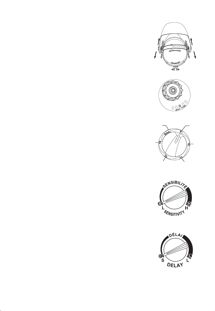
Le masque de soudeur photochromique est prêt à utiliser dès l’achat. Avant de commencer à
souder, vous n’avez qu’à ajuster la position du serre-tête et à choisir le numéro de teinte qui
convient au travail à effectuer.
• Ce masque de soudeur photochromique n’est pas conçu pour le soudage au laser ni pour
le soudage et le coupage oxyacétylénique.
• Ne posez jamais ce masque ni sa lentille photochromique sur une surface très chaude.
• Ne tentez jamais d'ouvrir ou d’altérer la lentille photochromique.
• Ce masque ne protège pas contre les engins explosifs ou les liquides corrosifs.
• N’apportez aucune modication à la lentille ni au masque, à moins que le présent guide
indique de le faire. N’utilisez aucune pièce de rechange autre que celles mentionnées dans
le présent guide. Les modications et l’utilisation de pièces de rechange non approuvées
annuleront la garantie et exposeront l’utilisateur à des risques de blessures.
• Si le masque ne s’assombrit pas dès l’amorçage d’un arc, arrêtez de souder
immédiatement et communiquez avec votre superviseur ou votre détaillant.
• N’immergez pas la lentille.
• N’appliquez aucun solvant sur la lentille ou les composants du masque.
• Utilisez le masque uniquement à des températures de -10 °C à 55 °C (14 °F à 131 °F).
• Température de rangement : -20 °C à 70 °C (-4 °F à 158 °F). Lorsque vous n’utiliserez
pas le masque pendant une longue période, vous devriez le ranger dans un endroit sec,
frais et sombre et en retirer la pile.
• Évitez que la lentille entre en contact avec les liquides et la saleté.
• Nettoyez régulièrement la surface de la lentille; n’utilisez aucune solution nettoyante
puissante. Nettoyez toujours les détecteurs et les piles solaires à l’aide d’un linge non
pelucheux propre.
• Remplacez immédiatement la lentille de protection avant si elle est ssurée, égratignée ou piquée.
• Ne tentez jamais d’ouvrir la cartouche ltrante.
• Dans certains cas, les matériaux qui entrent en contact avec la peau de l’utilisateur
peuvent causer des réactions allergiques.
• Veuillez insérer 2 piles alcalines AAA avant d’utiliser cet article.
• Si vous prévoyez ne pas utiliser le masque pendant une longue période, retirez-en les
piles an d’éviter de l’endommager.
Lisez attentivement toutes les instructions avant d’utiliser le masque
Masque de soudeur
de qualité professionnelle
CONSIGNES DE SÉCURITÉ – À LIRE AVANT D’UTILISER

9
• Le masque est assemblé en usine, mais avant de pouvoir l’utiliser, vous devez ajuster
convenablement le serre-tête et régler le délai, la sensibilité et le degré de teinte.
• AJUSTEMENT DU MASQUE
Vous pouvez agrandir ou raccourcir la circonférence du serre-tête en tournant le bouton
situé à l’arrière du serre-tête (voir l’ajustement « Y » à la g. 1). Cela s’effectue pendant
que vous portez le masque et permet un réglage parfait de la tension, c’est-à-dire que le
masque est ni trop lâche ni trop serré.
• Si le serre-tête remonte ou redescend trop, ajustez le harnais qui passe sur le dessus de
votre tête. Pour ce faire, dégagez l’extrémité du serre-tête en poussant la goupille hors du
trou percé dans le serre-tête. Faites glisser les deux portions du serre-tête, au besoin, pour
en agrandir ou en raccourcir la circonférence et poussez la goupille dans le trou le plus
près (voir l’ajustement « W » à la g. 1).
PROBLÈMES COURANTS ET SOLUTIONS
• Assombrissement irrégulier
Le serre-tête est mal positionné, et la distance entre les yeux et la lentille filtrante est
irrégulière (repositionnez le serre-tête pour réduire la différence de distance par rapport à
la lentille).
• La lentille photochromique ne s’assombrit pas ou vacille
① La lentille protectrice avant est souillée ou endommagée (remplacez la lentille protectrice).
② Les détecteurs sont souillés (nettoyez la surface des détecteurs).
③ Le courant de soudage est trop faible (réglez la sensibilité au niveau le plus élevé).
④ Assurez-vous que les piles sont en bon état et qu’elles sont bien installées. Vérifiez
également les surfaces et les bornes des piles et nettoyez-les au besoin.
• Réaction lente
La température d’utilisation est trop basse (n’utilisez pas le masque à une température
inférieure à -10 °C ou 14 °F).
• Mauvaise vision
① La lentille protectrice avant ou intérieure ou la lentille ltrante est souillée (remplacez la lentille).
② La lumière ambiante est insufsante.
③ Le numéro de teinte est mal réglé (réglez le numéro de teinte correctement).
• Le masque de soudeur glisse
Le serre-tête est mal ajusté (réajustez le serre-tête).
AVERTISSEMENT
L’utilisateur pourrait subir de graves blessures s’il ne respecte pas les avertissements
susmentionnés ou s’il ne suit pas le mode d’emploi.
AVERTISSEMENT
Si vous ne pouvez remédier aux problèmes ci-dessus, vous devez cesser immédiatement
d’utiliser le masque de soudeur photochromique. Communiquez avec le détaillant.
MODE D’EMPLOI
AVERTISSEMENT! Avant d’utiliser le masque pour souder, assurez-vous d’avoir lu
attentivement les consignes de sécurité.

10
W
Y
ZZ TT
• Vérifiez l’ajustement du serre-tête en relevant et en abaissant le
masque à quelques reprises pendant que vous le portez. Si le serre-
tête bouge, réajustez-le jusqu’à ce qu’il soit stable.
• RÉGLAGE DE LA DISTANCE ENTRE LE MASQUE ET LE VISAGE
Étape 1 : Débloquez le bouton de tension (voir « T » à la g. 1) pour
ajuster la distance verticale entre le masque et votre visage.
Étape 2 : Desserrez le bouton de tension gauche ou droit du masque
et éloignez ou rapprochez celui-ci de votre visage en le faisant
glisser (voir l’ajustement « Z » à la g. 1). Il est important que chacun
vos deux yeux soient à égale distance de la lentille. Sinon, l’effet
d’assombrissement pourrait vous paraître irrégulier.
Étape 3 : Resserrez le bouton de tension lorsque le réglage est
terminé.
• RÉGLAGE DE L’ANGLE DE VISION
Voir la g. 2
• CHOIX DU DEGRÉ DE TEINTE
Choisissez le degré de teinte selon le procédé que vous utiliserez.
Consultez la table des teintes à la fin du guide pour connaître les
degrés de teinte. Tournez le régulateur de teinte, situé sur le côté du
masque, jusqu’au numéro de teinte qu’il vous faut.
• ANNULATION DE LA TEINTE POUR LE MEULAGE
Lorsque le régulateur de teinte est à la position de meulage
(GRIND), la lentille ne s’assombrit pas. Vous pouvez ainsi bien
voir la soudure que vous meulez tout en ayant le visage protégé.
Avant de recommencer à souder, assurez-vous que la fonction
d’assombrissement a bien été activée (voir la g. 3).
• SENSIBILITÉ
La sensibilité peut être réglée à « H » (haute) ou « B » (basse)
au moyen du bouton de sélection situé à l’arrière de la cartouche
filtrante. Le réglage moyen-haut (Mid-High) est recommandé pour
l’utilisation quotidienne. Le réglage de sensibilité maximal convient
pour le soudage à faible courant, le soudage TIG ou les applications
spéciales. Lorsque la lumière ambiante excessive ou un autre
appareil de soudage se trouvant à proximité nuit au fonctionnement
du masque, utilisez le réglage bas (voir la fig. 4). Pour optimiser le
rendement, il est généralement recommandé de d’abord régler la
sensibilité au maximum, puis de la diminuer graduellement, jusqu’à
ce que la lentille ltrante réagisse uniquement au coup d’arc et qu’il
n’y ait aucun déclenchement indésirable attribuable aux conditions
d’éclairage (lumière directe du soleil, lumière articielle intensive, arcs
de soudage voisins, etc.).
g. 1
g. 2
g. 3
g. 4a
g. 4b
9
10
11
12
13
(Meulage)
GRIND
HAUT

11
• CHOIX DU DÉLAI
Lorsque vous avez terminé de souder, la lentille passe automatiquement de l’état sombre
à l’état clair selon un délai prédéterminé pour compenser toute incandescence résiduelle
provenant de la pièce à travailler. Le délai/la réaction peut être réglé(e) à « C » (court :
0,1 s) ou « L » (long : 1,0 s). Au besoin, utilisez le bouton de sélection situé à l’arrière de la
cartouche ltrante (voir la g. 4b). Il est recommandé d’opter pour un délai plus court lorsque
vous effectuez des soudures par points et pour un délai plus long lorsque vous soudez à
courant élevé. Un délai plus long convient également au soudage TIG à faible courant, car
cela permet d’éviter que la lentille s’ouvre lorsque les détecteurs d’arc sont temporairement
obstrués, notamment par une main ou un chalumeau, et ne peuvent capter la lumière.
Dénitions des abréviations sur la cartouche ltrante
« B » sur le bouton de sélection Sensibilité signie « Bas »
« H » sur le bouton de sélection Sensibilité signie « Haut »
« C » sur le bouton de sélection Sensibilité signie « Court »
« L » sur le bouton de sélection Sensibilité signie « Long »
• ESSAI
Avant d’utiliser le masque, appuyez sur le bouton d’essai (TEST) pour vérifier si la
lentille photochromique fonctionne bien; si elle ne s’assombrit pas, remplacez les piles
immédiatement. Maintenez enfoncé le bouton d’essai pour avoir un aperçu de la teinte
choisie avant de commencer à souder (voir la g. 5). Lorsque vous relâchez le bouton, la
lentille revient automatiquement à l’état clair (teinte 3,5).
• ALIMENTATION
Cette cartouche filtrante est alimentée par une pile solaire et deux piles alcalines AAA.
Remplacez les piles lorsque l’indicateur de piles faibles (LOW BATTERY) est allumé (voir la
g. 5).
• Vous êtes maintenant prêt à utiliser le masque. Vous pouvez régler la teinte pendant
l’utilisation en réinitialisant le potentiomètre.
LOW
BATTERY
BATTERIE
FAIBLE
ESSAI
TEST
g. 5

12
• REMPLACEMENT DE LA LENTILLE DE PROTECTION AVANT
Remplacez la lentille de protection avant si elle est endommagée (c.-à-d. fissurée,
égratignée, souillée ou piquée). Placez votre pouce ou un autre doigt dans la cavité se
trouvant à l’extrémité inférieure de la lentille et repliez celle-ci vers le haut jusqu’à ce qu’elle
se dégage d’un côté (voir la g. 6).
• REMPLACEMENT DE LA LENTILLE DE PROTECTION INTÉRIEURE
Remplacez-la si elle est ssurée, égratignée, souillée ou piquée.
• REMPLACEMENT DE LA CARTOUCHE FILTRANTE (voir les g. 6a et 6b)
• INSTALLATION D’UNE NOUVELLE CARTOUCHE
Prenez la nouvelle cartouche filtrante et passez le câble du potentiomètre sous l’anse
métallique avant de déposer la cartouche dans son logement à l’intérieur du masque.
Enfoncez la xation et assurez-vous que l’extrémité avant de l’anse est bien xée sous
les languettes de retenue comme l’illustre la g. 6b.
• Fixez le potentiomètre à l’intérieur du masque en faisant dépasser l’axe par le trou. Appuyez
le régulateur de teinte contre l’axe.
• NETTOYAGE
Nettoyez le masque en l’essuyant à l’aide d’un linge doux. Nettoyez régulièrement les
surfaces de la cartouche. N’utilisez aucune solution nettoyante puissante. Nettoyez les
détecteurs et les piles solaires à l’aide d’alcool dénaturé et d’un linge propre et essuyez-les
complètement à l’aide d’un linge non pelucheux propre.
ENTRETIEN
g. 6
g. 6b
g. 6a

13
FICHE TECHNIQUE
Classe optique :
Champ visuel :
Dimensions de la cartouche :
Détecteurs d’arc :
État clair :
État sombre :
Régulateur de teinte :
Mise en marche / Arrêt :
Réglage de la sensibilité :
Protection UV/IR :
Alimentation :
Temps de transition :
Délai (de clair à sombre) :
Capacité nominale TIG à faible intensité :
Meulage :
Température d’utilisation :
Température de rangement :
Matériau :
Poids total :
Applications :
Normes :
1 / 1 / 1 / 2
3 7/8 po x 1 7/8po
4 21/64 po x 3 1/2 po x 23/64 po
2
DIN 3.5
DIN 9-13
Externe, teinte variable
Entièrement automatique
De bas à haut, au moyen du bouton de sélection
Jusqu’à la teinte DIN16 en tout temps
Pile solaire et 2 piles alcalines AAA rechargeables
1/16 000 s, de clair à sombre
0,1 à 1,0 s, au moyen du bouton de sélection
≥ 5 A, CC; ≥ 5 A, CA
Oui
-10 °C à 55 °C (14 °F à 131 °F)
-20 °C à 70 °C (-4 °F à 158 °F)
Nylon à résistance élevée aux chocs
500 g
Soudage à l’arc (CC et CA), TIG (CC, impulsion
de CC), TIG (impulsion de CA), excellente
réaction au soudage TIG à faible intensité,
MIG/MAG, MIG/MAG à impulsion, soudage et
coupage au plasma, meulage, non conçu pour
le soudage au laser ni pour le soudage ou le
coupage oxyacétylénique
ANSI Z87.1 et CSA Z94.3

14
LISTE DES PIÈCES ET ASSEMBLAGE
14
1. Coque (masque de soudeur)
2. Lentille de protection avant
3. Lentille photochromique
4. Lentille de protection intérieure
5. Rondelle de retenue gauche
6. Rondelles angulaires ajustables (2)
7. Rondelles (2)
8. Boutons de tension (2)
9. Rondelle de retenue droite
10. Vis (2)
11. Serre-tête ajustable
12. Bandeau absorbant
13. Bouton de sélection
14. Régulateur de teinte
15. Couvercle des piles
REMARQUE :
SMAW – Shielded Metal Arc Welding (Soudage à l’arc avec électrode enrobée)
MIG (lourds) – Soudage MIG sur métaux lourds
MIG (légers) – Soudage MIG sur métaux légers
TIG, GTAW – Gas Tungsten Arc Welding (Soudage à l’électrode de tungstène)
MAG/CO2 - Metal Active Gas (Soudage à l’arc en atmosphère active)
SAW – Shielded Semi-Automatic Arc Welding (Soudage à l’arc semi-automatique)
PAC – Plasma Arc Cutting (Coupage au plasma)
PAW – Plasma Arc Welding (Soudage au plasma)
Garantie : un (1) an contre les défauts de fabrication et de matériau(x). Exclusion : usure
ou bris causés par un usage abusif ou inapproprié.
GARANTIE
10 11
SMAW
MIG(heavy)
MIG(light)
TIG,GTAW
MAG/CO2
SAW
PAC
PAW
9 10 11 12 13 14
12 13 14
12 13 14 15
10 11
12 13 14
10
911
12 13 15
14
10 11
12 13
11
12 13 15
14
1110
98
12 13 15
14
11
10
Welding Process 0.5 2010 40 80 125 175 275 450350
500
400
300
250
200150
100
60
3015
5
1
225
2.5
ARC CURRENT(Amperes)
SHADE GUIDE TABLE (NO.1)

Table of contents
Languages:
Other MasterCraft Welding Accessories manuals
Popular Welding Accessories manuals by other brands

3M
3M Speedglas 9002NC user manual

Miller Electric
Miller Electric MC-80 owner's manual

Miller Electric
Miller Electric XR A owner's manual

Toparc
Toparc 068636 manual

Magswitch Technology Inc.
Magswitch Technology Inc. Multi-Angle 400 Magvise Operation and instruction manual

Miyachi
Miyachi MM-601B Operation manual

ESAB
ESAB Origo Feed 304 P4 User manual and spare parts

Abicor Binzel
Abicor Binzel ABIMIG 0 Series operating instructions

AOSafety
AOSafety Welding Filter Plates Weld-Cool brochure

ESAB
ESAB A2 S GMAW Mini Master instruction manual

RUD
RUD LPW 300 manual

Abicor Binzel
Abicor Binzel ABIMIG operating instructions