Please dispose of packaging for the product in a responsible man-
ner. It is suitable for recycling. Help to protect the environment.
Take the packaging to the local amenity tip and place into the
appropriate recycling bin.
Never dispose of electrical equipment or batteries in with your
domestic waste. If your supplier offers disposal facility please use
it or alternatively use your local amenity tip and dispose in the
correct manner. This will allow the recycling of raw materials and
help protect the environment.
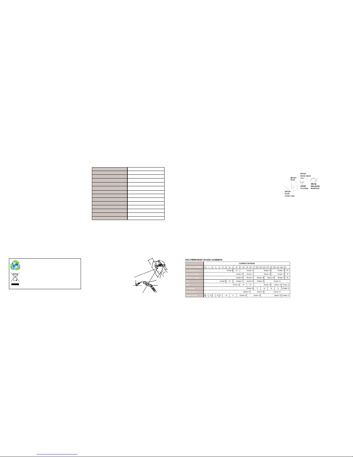
3. SELECT THE SHADE NUMBER
The shade is infinitely adjustable between shade 9 and 13
The shade number can be selected by turning the shade knob on the side of the
helmet.
The set shade is indicated by the arrow on the knob.
4. SELECT DELAY TIME
The delay time can be set using the delay knob on the inside of the filter (the side
you look through) it can be set variably between MAX which is 1.0 second or MIN
which is 0.1 second.
MAX – Longer delay is for most welding applications. Especially for high amperage
applications
MIN –Shorter delay can be used for applications such as tacking, spot welding.
Longer delay can also be used for TIG welding in order to prevent the filter returning
to the clear state when the sensor is briefly covered by the hand, torch, etc. Long
delay also protects against weld after glow.
5. SELECT THE SENSITIVITY
The sensitivity can be adjusted by rotating the knob on the inside of the helmet. This
alters the sensitivity of the helmet to ambient light levels. On low sensitivity the filter
will not switch due to sunlight or welders working nearby. On high sensitivity the hel-
met will respond better to small arcs or TIG welding. The set sensitivity is indicated
by the by the arrow on the knob.
6. SELECT GRINDING MODE
To select the grinding mode rotate the shade knob clockwise to the top position
once the arrow has gone past shade 13 a click should be felt this means the filter is
now set to grind mode.
PLEASE NOTE Grind mode is intended for grinding and not for welding. Before
you restart welding please set the filter back to weld mode and select the required
shade for your application to do this rotate the shade knob anti-clockwise.
PARTS LIST
MAINTENANCE
REPLACEMENT OF FRONT COVER LENS
• Remove the front cover lens by pulling outwards at the base of the lens using the
finger slot provided.
• Make sure the protective films are removed from new cover lens.
• Place the new cover lens in the recess at the front of the helmet
• Locate the cover lens under the lugs at the left of the filter and then flex the lens
so that it can be inserted under the lugs on the right had side of the filter.
• Only use genuine Parweld cover lenses, using lower grade lens may cause warp-
ing and allow spatter to damage the filter so invalidating the warranty. This may
also reduce the impact rating.
NOTE- Do not use the helmet without the cover lens in place
REPLACEMENT OF INNER COVER LENS
• The welding inner cover lens is removed by pulling out the top edge.
• The new inner cover lens is assembled after the protective film is removed. Locate
one of the sides by inserting the edge under the frame at the side and bend the
lens in the middle part and locate the lens under the frame at the other side.
XR935H Everyday Light Reactive
Welding and Grinding Helmet
WARNING
Please read and understand all instructions prior to using the Parweld
XR935H Everyday light reactive welding and grinding helmet.
GENERAL INFORMATION
This Parweld XR935H Everyday Light Reactive Welding and Grinding Helmet will
not protect against severe impact hazards, such as explosive devices or corrosive
liquids. Machine guards or eye splash protection must be used when these hazards
are present.
All Parweld light reactive welding filters are for use in Arc welding or cutting appli-
cations. This unit is suitable for all Arc processes such as MIG, MAG, TIG, SMAW,
Plasma Arc and Carbon Arc.
Use this helmet only for face and eye protection against harmful rays, sparks and
spatter from Welding, Grinding and Cutting.
The Parweld XR935H everyday light reactive helmet is not suitable for “overhead”
welding applications, Laser welding, Laser cutting applications, gas welding or
cutting
In the event of electronic failure, the welder remains protected against UV and IR
Radiation according to Shade 16.
The Parweld light reactive welding filter should always be used with original Parweld
inner and outer cover lenses.
The manufacturer is not responsible for any modifications to the welding filter or the
use of the filter in any other manufacturer’s helmet.
Protection can be seriously impaired if unapproved modifications are made.
TECHNICAL SPECIFICATIONS
Viewing Area 100 x 41mm (3.93” x 1.62”)
Cartridge Size 110 x 90 x 8mm (4.33” x 3.54” x 0.31”)
UV/IR Protection Permanent DIN Shade 16
Light State DIN Shade 4
Dark State DIN Shade 9 to 13 Variable
Power Supply Solar Cell with Built-in Battery
Power On/Off Fully Automatic
Switching Time Light to Dark <1/30,000s
Dark to Light 0.1 - 1.0s (Internal Variable)
Operating Temperature -10ºC to +60ºC
Storage Temperature -20ºC to +70ºC
Helmet Material High Impact Polyamide Nylon
Total Weight 460g
Minimum Operating Amperage 10 Amps
DO
Ensure the front cover lens is fitted before use and remove protective film.
Ensure that the lens is clean and there is no dirt or spatter covering the 2 sensors at
the front of the filter.
Inspect all parts for signs of wear or damage. Any scratched or cracked parts should
be replaced prior to use.
DON’T
Never place the helmet on a hot surface
Never open or tamper with the filter cartridge.
OPERATION
1. ADJUST THE WELDING HELMET ACCORDING
TO INDIVIDUAL REQUIREMENTS
The headband should be adjusted both in diameter and height.
The angle between face and helmet should be
adjusted and is recommended to be
10° - 12°.
2. ON/OFF
The solar unit automatically switches on when
exposed to light.
10˚-12˚