GECKO OPERATOR’S MANUAL
3
www.itmtools.com.au
Contents
1. GENERAL INFORMATION ............................................................................................... 3
1.1. Application ................................................................................................................. 3
1.2. Technical data............................................................................................................ 3
1.3. Equipment included ................................................................................................... 4
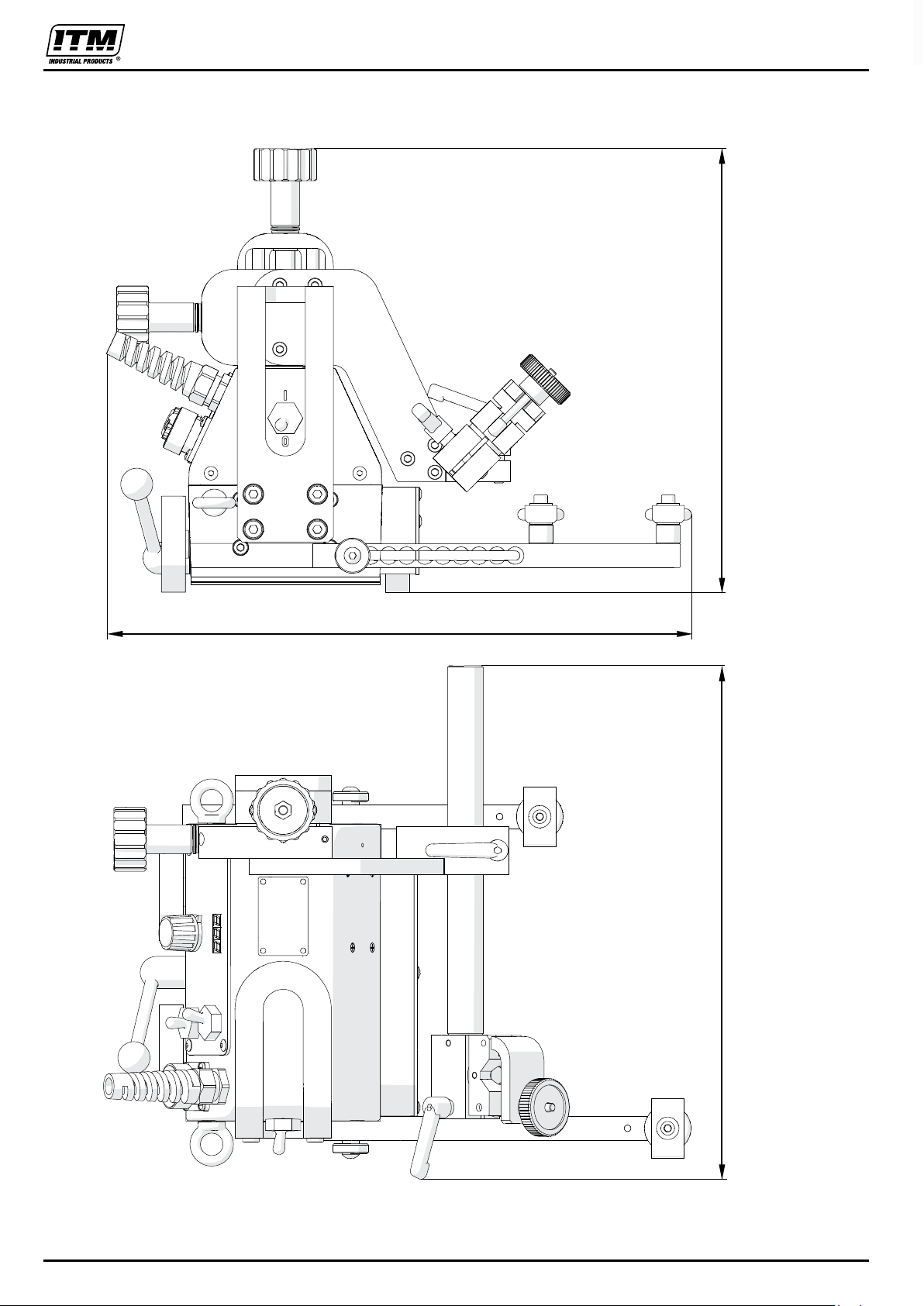
1.4. Dimensions ................................................................................................................ 5
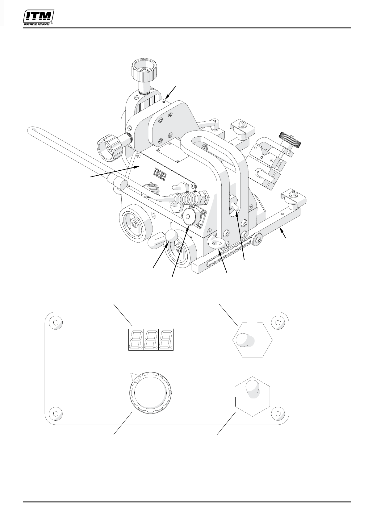
1.5. Design ....................................................................................................................... 6
2. SAFETY PRECAUTIONS.................................................................................................. 7
3. STARTUP AND OPERATION ........................................................................................... 9
3.1. Preparing ................................................................................................................... 9
3.2. Connecting to the welding circuits.............................................................................10
3.3. Positioning at the worksite ........................................................................................11
3.4. Operating ..................................................................................................................12
3.5. Changing the unit of speed .......................................................................................13
3.6. Troubleshooting ........................................................................................................14
4. MAINTENANCE ...............................................................................................................15
5. ACCESSORIES ...............................................................................................................16
5.1. Torch clamps ............................................................................................................16
5.2. Rods .........................................................................................................................17
5.3. Torch holders............................................................................................................18
5.4. Torch extension arm .................................................................................................20
5.5. Guide arms ...............................................................................................................21
5.6. Dual torch mount.......................................................................................................26
5.7. Auxiliary magnet blocks ............................................................................................27
5.8. Flexible guide set ......................................................................................................28
5.9. Guide adjustment tool ...............................................................................................30
5.10. Flexible trackway set...............................................................................................31
5.11. Magnetic units for flexible trackway .........................................................................34
5.12. Support for trackway with magnetic units ................................................................38
5.13. Vacuum unit ............................................................................................................39
5.14. Vacuum track system..............................................................................................40
5.15. Support for trackway with vacuum units ..................................................................41
5.16. 76 mm cross slide ...................................................................................................42
5.17. Cable anchor...........................................................................................................43
5.18. Display protection shield .........................................................................................43
5.19. Fall arrester.............................................................................................................44
5.20. Stainless steel wheels.............................................................................................45
6. 115–230 V WIRING DIAGRAM ........................................................................................46
7. 115–230 V HS WIRING DIAGRAM ..................................................................................47
8. 42 V WIRING DIAGRAM..................................................................................................48
9. 42 V HS WIRING DIAGRAM ............................................................................................49
10. DECLARATION OF CONFORMITY ...............................................................................50
11. WARRANTY CARD........................................................................................................51
1. GENERAL INFORMATION............................................................................................... 4
1.1. Application...................................................................................................................... 4
1.2. Technical data ................................................................................................................ 4
1.3. Equipment included........................................................................................................ 5
1.4. Dimensions..................................................................................................................... 6
1.5. Design ............................................................................................................................ 7
2. SAFETY PRECAUTIONS................................................................................................. 8
3. STARTUP AND OPERATION .......................................................................................... 10
3.1. Preparing........................................................................................................................ 10
3.2. Connecting to the welding circuits.................................................................................. 11
3.3. Positioning at the worksite.............................................................................................. 12
3.4. Operating........................................................................................................................ 13
3.5. Changing the unit of speed............................................................................................. 14
3.6. Troubleshooting.............................................................................................................. 15
4. MAINTENANCE................................................................................................................ 15
5. ACCESSORIES................................................................................................................ 16
5.1. Torch clamps.................................................................................................................. 16
5.2. Rods ............................................................................................................................... 17
5.3. Torch holders.................................................................................................................. 18
5.4. Torch extension arm....................................................................................................... 20
5.5. Guide arms..................................................................................................................... 21
5.6. Dual torch mount ............................................................................................................ 26
5.7. Auxiliary magnet blocks.................................................................................................. 27
5.8. Flexible guide set............................................................................................................ 28
5.9. Guide adjustment tool..................................................................................................... 30
5.10. Flexible trackway set .................................................................................................... 31
5.11. Magnetic units for flexible trackway.............................................................................. 34
5.12. Support for trackway with magnetic units..................................................................... 38
5.13. Vacuum unit.................................................................................................................. 39
5.14. Vacuum track system ................................................................................................... 40
5.15. Support for trackway with vacuum units....................................................................... 40
5.16. 76 mm cross slide......................................................................................................... 41
5.17. Cable anchor ................................................................................................................ 42
5.18. Display protection shield............................................................................................... 42
5.20. Stainless steel wheels .................................................................................................. 43
115–230 V WIRING DIAGRAM............................................................................................. 44
115–230 V HS WIRING DIAGRAM....................................................................................... 45
42 V WIRING DIAGRAM....................................................................................................... 46
42 V HS WIRING DIAGRAM................................................................................................. 47
PARTS LIST.......................................................................................................................... 48
PARTS LIST - ASSEMBLY PANEL....................................................................................... 54
PARTS LIST - TORCH HOLDING ASSEMBLY & LOW TORCH HOLDING ASSEMBLY.... 55