Swagelok 40 series User manual

www.swagelok.com
English. . . . . . . . . . . . . . . . . . . . . . . . . . . . . 1
Japanese (日本語) . . . . . . . . . . . . . . . . . . . . . 33
Series 40
Weld Head
User’s Manual

ii Series 40 Weld Head User’s Manual

www.swagelok.com
Weld Head
User’s Manual
MS-13-206.indb 1 2/1/13 3:03 PM

2Series 40 Weld Head User’s Manual
Contents
Description . . . . . . . . . . . . . . . . . . . . . . . . . . . . . . .5
Unpacking the Weld Head Components . . . . . . . . . . . . . . .6
Installing the Weld Head. . . . . . . . . . . . . . . . . . . . . . . .7
Selecting the Electrode . . . . . . . . . . . . . . . . . . . . . . . .8
Installing the Electrode . . . . . . . . . . . . . . . . . . . . . . . 10
Preparing the Work . . . . . . . . . . . . . . . . . . . . . . . . . 11
Operating the Weld Head . . . . . . . . . . . . . . . . . . . . . . 12
Performing Daily Maintenance . . . . . . . . . . . . . . . . . . . 14
Performing Periodic Maintenance . . . . . . . . . . . . . . . . . 15
Weld Head Cleaning and Inspection . . . . . . . . . . . . . . . . 16
Specifications . . . . . . . . . . . . . . . . . . . . . . . . . . . . 20
Parts Drawings . . . . . . . . . . . . . . . . . . . . . . . . . . . .21
MS-13-206.indb 2 2/1/13 3:03 PM

Series 40 Weld Head User’s Manual 3
Description
Swagelok series 40 welding system components deliver consistent,
precise welds for outside tube diameters ranging from 1 1/2 to 4 in.
and 38.1 to 114.3 mm and pipe diameters ranging from 1 ¼ to 4 in. and
42.2 to 114.3 mm.
A dc motor in the weld head drives a rotor, which revolves the tungsten
electrode around the weld joint. Optical circuitry in the weld head
sends precise feedback to the power supply to control the speed of
the rotor.
All moving parts in the weld head are mounted in low-friction devices
to provide smooth, consistent operation.
A spring-loaded, oating brush maintains contact with approximately
two-thirds of the circumference of the rotor. This conguration ensures
consistent, uniform electrical conductance to the rotor and electrode. Figure 1 Series 40 Weld Head
MS-13-206.indb 3 2/1/13 3:03 PM

4Series 40 Weld Head User’s Manual
Unpacking the Weld Head Components
The weld head assembly and tool package are packaged in a foam-
lined shipping container. Perform the following steps when your
Swagelok series 40 weld head arrives.
1. Inspect the container for damage.
2. Remove the components from the container.
3. Check the items for any damage.
4. Verify that the weld head serial number matches the serial number
on the shipping container.
5. Record the model and serial numbers, and the delivery dates on
the Registration Information page of your power supply user’s
manual.
MS-13-206.indb 4 2/1/13 3:03 PM

Series 40 Weld Head User’s Manual 5
Installing the Weld Head
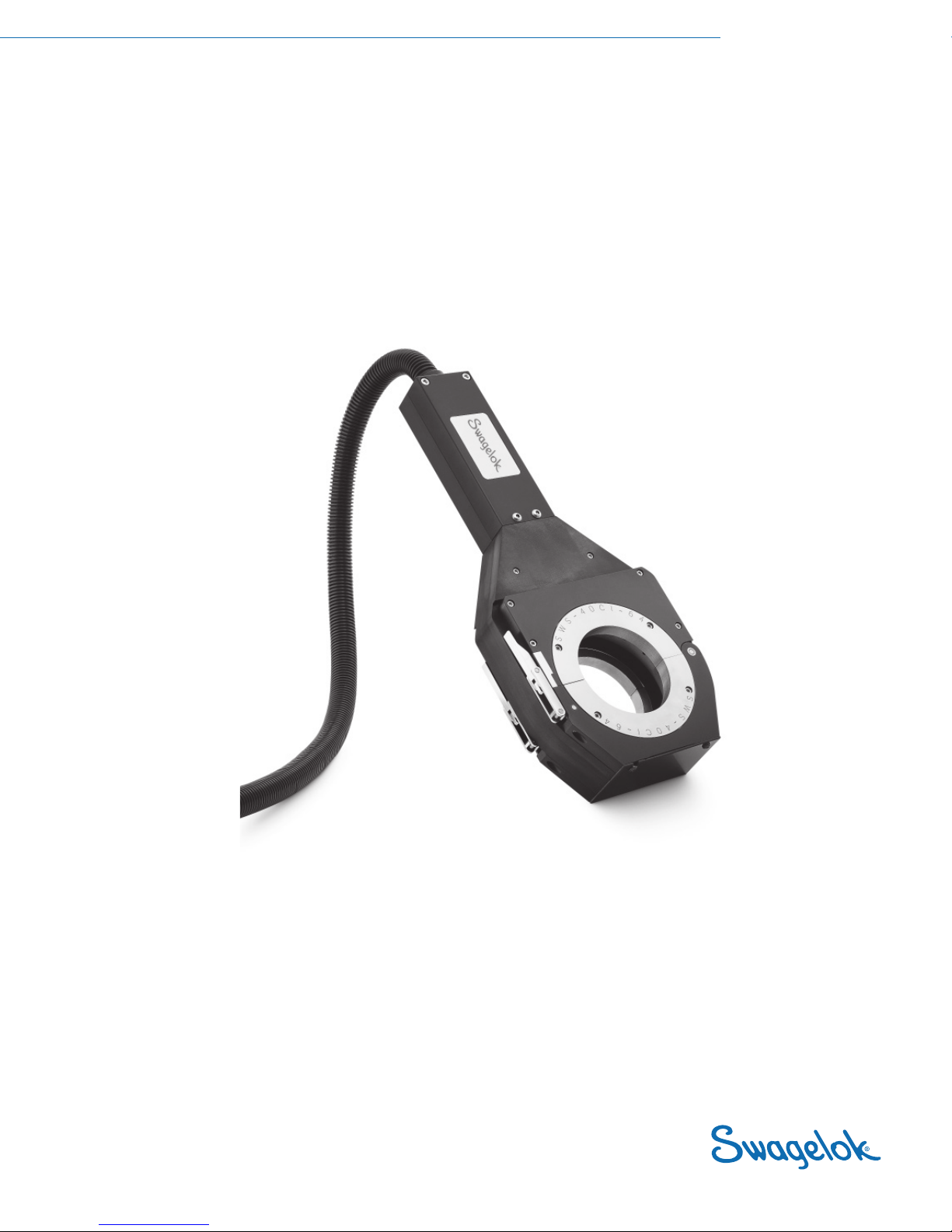
The weld head assembly has four connectors that plug into the power
supply. See Figure 2.
The four connectors on the cable are:
• weld head
• electrode (red)
• work (green)
• weld head shielding gas
Connect the four connectors to the side panel of the power supply by
performing the following steps. See Figure 3.
1. Locate the weld head cable assembly.
2. Align the notch on the one-quarter turn connector with the small
tab in the mating socket on the side panel labeled WELD HEAD.
Insert the connector in the socket. Turn the connector sleeve
clockwise by hand until it is tight. This connection provides the
control signals to drive the weld head.
3. Insert and fully seat the red connector into the socket on the side
panel labeled ELECTRODE. Twist the connector 1/4-turn clockwise
to lock it into place. This connection is the negative (-) terminal of
the weld head.
4. Insert the green connector into the socket on the side panel
labeled WORK. Twist the connector 1/4-turn clockwise to lock it
into place. This connection is the positive (+) terminal of the weld
head.
5. Insert the weld head shielding gas connector into the Swagelok
Quick-Connect stem labeled TO WELD HEAD. Ensure that the
connector is rmly attached. This connection provides shielding
gas to the weld head through a mass ow controller in the power
supply.
Figure 2 Weld Head Assembly
Figure 3 Weld Head Connectors
Caution!
Ensure that the weld head connector
is fully seated in the mating socket
and the threaded sleeve is tight.
Note:
The weld head shielding gas connector must
be a single-end shut-off (SESO) Swagelok
Quick-Connect stem (SS-QC4-S-400).
Weld Head Electrode
Work
Weld Head
Shielding
Gas
MS-13-206.indb 5 2/1/13 3:03 PM

6Series 40 Weld Head User’s Manual
Selecting the Electrode
Electrode length depends on the desired arc gap and outside diameter
of the work piece being welded. To select the correct electrode use
the Tungsten Electrode Length Calculation. Once you have the correct
length calculated either select an electrode from stock using the
Electrode Selection Table or place a special order.
Tungsten Electrode Length Calculation
To determine the tungsten electrode length for a specic arc gap, use the formula below:
(Rotor OD ÷ 2) − (Tube OD ÷ 2) − Arc Gap = Electrode Length
Figure 4 Electrode Length Calculation Parameters
Example No. 1: (1.5 in. to 1.5 in. tube butt weld)
Rotor OD A = 6.850 in.
Tube outside diameter B = 1.500 in.
Desired arc gap C = 0.060 in.
(6.850 ÷ 2) − (1.500 ÷ 2) − 0.060 in. = 2.615 in.
Example No. 2: (38,1 mm to 38,1 mm tube butt weld)
Rotor OD A = 173,99 mm
Tube outside diameter B = 38,10 mm
Desired arc gap C = 1,52 mm
(173,99 ÷ 2) − (38,10 ÷ 2) − 1,52 mm = 66,425 mm
A
Rotor OD
B
Tube
OD
C
Arc Gap
Electrode
Length
Rotor OD = 6.850 in. (173,99 mm)
MS-13-206.indb 6 2/1/13 3:03 PM

Series 40 Weld Head User’s Manual 7
Table 1 Electrode Selection for 0.060 in. Arc Gap
Electrode
Ordering Number
Component
OD
Electrode
Length
L
Electrode
Diameter
D
SWS-C.094-2.615-P 1.5 in. 2.615 in.
(66,40 mm)
0.094 in.
(2,39 mm)
SWS-C.094-2.365-P 2.0 in. 2.365 in.
(60,07 mm)
0.094 in.
(2,39 mm)
SW S- C. 0 94 -2 .115 - P 2.5 in. 2.115 in.
(53,72 mm)
0.094 in.
(2,39 mm)
SWS- C.094-1.865-P 3.0 in. 1.865 in.
(47,37 mm)
0.094 in.
(2,39 mm)
SWS- C.094-1.615-P 3.5 in. 1.615 in
(41,02 mm)
0.094 in.
(2,39 mm)
SWS- C.094-1.365-P 4.0 in. 1.365 in.
(34,67 mm)
0.094 in.
(2,39 mm)
SW S- C. 09 4 -1.10 5 - P 4.5 in. 1.105 in.
(28,07 mm)
0.094 in.
(2,39 mm)
Electrode Geometry
This illustration shows the electrode shape Swagelok suggests.
Properly ground electrodes provide consistent, repeatable welds. Pre-
ground electrodes are available from your Swagelok representative.
See the Orbital Welding System, Series 40, catalog, MS-02-140, for
ordering information.
The electrode ordering numbers are assigned as follows:
SWS – X.### – #.### – P
The ceriated electrode material type is a mixture of 98 % tungsten
and 2 % cerium and is commonly referred to as “2 % ceriated.” This
electrode type has demonstrated improved arc starting performance
over the 2 % thoriated type, particularly when using puried shielding
gas.
Note:
Auto generated programs are exact lengths.
You may substitute another length that is
within 0.005 in.
Figure 5 Tungsten Electrode
Material Designator
C= Ceriated
Package
Designator
Electrode
Diameter
Electrode
Length
MS-13-206.indb 7 2/1/13 3:03 PM

8Series 40 Weld Head User’s Manual
Installing the Electrode
1. With the weld head in the open position, press JOG or
ELECTRODE CHANGE on the operator panel until the tungsten
electrode is in the position shown in Figure 6.
2. Loosen the electrode set screw. Remove the electrode if you are
replacing it.
3. Insert the new electrode until it is ush with the outside edge of the
rotor.
4. Tighten the electrode set screw to secure the electrode.
5. Press HOME or ELECTRODE CHANGE on the operator front
panel to return rotor to the home position.
Figure 6 Electrode Installation
Caution!
Do not jog or move the rotor unless
the electrode is clamped in place.
Caution!
The rotor will move when
ELECTRODE CHANGE is pressed.
The rotor is a potential pinch point.
Electrode
Electrode
Set Screw
Outside Edge
of Rotor
MS-13-206.indb 8 2/1/13 3:03 PM

Series 40 Weld Head User’s Manual 9
Preparing the Work
It is important to prepare the tube pieces properly before welding. See
Figure 7.
Tubing must be square and burr-free to ensure repeatable, high-
quality autogenous fusion welds.
Cut the tubing to length with a hacksaw or tube cutter. Face the tube
ends with a lathe or a portable facing tool. Deburr the ends, making
sure that both the inside and outside diameters are square and burr-
free. Clean the tube ends using an appropriate solvent.
Minimize the chance of a poor quality weld by following these
guidelines:
• Tube ends must be square.
• Tube ends must not have a wall thickness variation exceeding
± 15 % of nominal.
• Tube ends must be burr-free.
• Tube ends must be free of any rust, grease, oil, paint, or other
surface contaminates.
Figure 7 Tube Preparation
Method Result
Burrs Burrs in Flow Path
Burrs
End Rolled by Cutter
Blade and Roller
Irregular Tube
Diameter
Face Perpendicular
to Axis
Smooth Transition at
Wall Faces
Reduced Flow Area
Gap
Hacksaw Cut
Tube Cutter
Tube Facing Tool
MS-13-206.indb 9 2/1/13 3:03 PM

10 Series 40 Weld Head User’s Manual
Operating the Weld Head
Operate the weld head using the following parameters:
Series 40
Shield Gas Flow Rate
std ft3/h (std L/min)
30 to 50➀
(14 to 23)
Minimum Prepurge and
Postpurge Time 45➁seconds
Maximum Recommended
Average Amps 100 A➂
➀Set flow to higher rates when welding at high current rates.
➁Flow should be continuous for cooling when welding at high current rates.
➂When using optional weld lens over viewport, max is 120 A @ 50 % duty cycle.
Collet Installation
1. Select the appropriate set of collets according to the tube OD of
the tubing to be welded.
2. Remove the four screws holding the collets on each side of the
weld head.
3. Install the selected collet.
4. Reinstall the screws.
Work Piece Alignment
1. Open the window cover.
2. Open one of the xture side plates.
3. Insert the rst work piece aligning it with the tungsten electrode.
4. Close and latch the xture side plate.
5. Open the other xture side plate.
6. Insert the second work piece and butt the weld ends together.
7. Close and latch the xture side plate.
8. Inspect the alignment by looking through the window cover to
verify that the two work pieces are centered on the tungsten
electrode.
Figure 8 Installing the Collet
Figure 9 Aligning the Work Piece with the
Electrode
Screws
(Qty. 4)
MS-13-206.indb 10 2/1/13 3:03 PM

Series 40 Weld Head User’s Manual 11
Latch Tension Adjustment
1. Adjust the latch adjustment screws so that the latch is in position
to exert appropriate tension on the tube.
Weld Head Mounting
1. Bolt the mounting bracket to the top of the bench.
2. Thread the power cord through the opening of the mounting
bracket and seat the weld head in the position shown in Figure 11.
Figure 10 Adjusting the Latch Tension
Figure 11 Mounting the Weld Head
Note: The weld head may be mounted as
illustrated or turned 90°.
Latch Adjustment
Screws
MS-13-206.indb 11 2/1/13 3:03 PM

12 Series 40 Weld Head User’s Manual
Performing Daily Maintenance
To keep your Swagelok welding system (SWS) equipment in proper
working order, you must perform daily maintenance on the system
components.
Store the weld head in a clean, dry place.
At the start of each workday remove dirt, carbon, and vapor deposits
from the weld head rotor area with a clean, soft cloth and a solvent
such as isopropyl alcohol.
Note: If you experience problems while
performing the procedures in this section,
refer to Troubleshooting in power supply
user’s manual or contact your authorized
Swagelok representative.
Figure 12 Inspect Exposed Surfaces of the
Weld Head
Rotor Area
MS-13-206.indb 12 2/1/13 3:03 PM

Series 40 Weld Head User’s Manual 13
Performing Periodic Maintenance
This section describes the procedures necessary for maintaining the
weld head after every 400 to 500 welds.
Parts that are found to be defective during this procedure should be
replaced. For detailed part drawings and ordering information, refer to
the Part Drawings at the end of this manual. Spare parts are available
through your authorized Swagelok representative.
1. Verify the xture side plate will properly secure the work piece.
a. Install collets into one side of the xture side plate.
b. Insert nominal sized tubing and close the xture side plate
using the lever cams.
c. Verify the tubing does not rotate in the collets.
d. Verify the tubing does not slide side-to-side in the collets.
e. Verify the tubing does not move up and down or left to right in
the collets.
f. Repeat for the other side of the xture side plate.
g. Contact your authorized Swagelok representative to return the
xture side plate for service.
WARNING!
DISCONNECT THE WORK AND
ELECTRODE CABLES FROM THE
POWER SUPPLY BEFORE PERFORMING
MAINTENANCE.
Caution!
Do not use lubricants inside the
weld head.
Figure 13 Verifying Work Piece is Secure
MS-13-206.indb 13 2/1/13 3:03 PM

14 Series 40 Weld Head User’s Manual
Weld Head Cleaning and Inspection
This section describes how to disassemble the weld head and rotor.
Weld Head
To disassemble the weld head, follow these steps:
1. Blow any loose material from the weld head assembly with clean,
low-pressure air.
2. Remove the four screws from the left xture side plate. See Figure
14.
3. Using a at-bladed screwdriver, evenly pry the left xture side
plate off of the weld head housing being careful not to damage
ends of threaded alignment studs.
4. Remove the long motor cover screws and the motor cover end
screws. See Figure 15.
5. Remove the four weld head housing screws from the housing.
Using a at blade screwdriver, carefully separate the brush side
from the gear side. See Figure 16.
6. Carefully separate the weld head housing halves so that internal
components, such as the ground pin insulators and xture pin
insulator are not damaged. See Figure 16.
Figure 14 Removing the Left Fixture
Side Plate
Figure 16 Disassembling the Weld
Head Housing
Figure 15 Removing the Motor Cover
Note: As you remove the screws from the
weld head organize them so that you can
reinstall them in their original holes upon
reassembly.
Motor Cover
Screws—Long
(Qty. 2)
Motor Cover
End Screws
(Qty. 2)
Weld Head Housing
Screws (Qty. 4)
Screws
(Qty. 4)
MS-13-206.indb 14 2/1/13 3:03 PM

Series 40 Weld Head User’s Manual 15
Brush
1. Remove the three brush screws and the two clamping plate
screws.
2. Remove the brush from the brush side of the housing assembly.
See Figure 17.
3. Inspect and clean the brush using the following steps:
• Checkthebrushforexcessivewear.ContactyourSwagelok
representative if replacement is necessary.
• Removeanyoxidationfromthebrushsurfaceandbrushclamp
plate with a nylon abrasive pad.
• Turnthebrushoverandremoveanyoxidationfromthearea
that contacts the brush clamp plate with a nylon abrasive pad.
• Removetheresidueleftbytheabrasivepadusingisopropyl
alcohol and a lint-free pad.
• Removeresiduefromthebrushgroovewithisopropylalcohol
and a lint-free pad.
4. Reinstall the brush making sure the springs are fully seated in the
brush housing.
5. Screw the two short screws into the brush clamp plate.
6. Screw the three long screws into the brush housing.
Figure 17 Removing the Brush
Note: The brush clamp plate is attached with
two Torx Plus IP-8 screws. Use a Torx Plus T8
wrench to remove
Caution!
Be careful not to strip the heads or
screw threads.
Note: The brush should demonstrate a spring
action if installed properly.
Brush Screws
(Qty. 3)
Clamping
Plate Screws
(Qty. 2)
MS-13-206.indb 15 2/1/13 3:03 PM

16 Series 40 Weld Head User’s Manual
Rotor
1. Inspect the gears for wear and replace if damaged by referring to
the Gear Side Assembly drawing on page 24.
2. Remove the rotor from the gear side of the housing assembly. See
Figure 18.
3. Place the rotor on a clean, dry surface.
4. Inspect the rotor bearing assemblies for wear and damage.
Contact your Swagelok representative if replacement is necessary.
5. f the rotor bearing assemblies are dirty, clean them with isopropyl
alcohol.
6. Inspect the rotor for dirt and other deposits. Remove dirt or other
deposits with a nylon abrasive pad.
7. Remove residue from the rotor track with isopropyl alcohol and a
lint-free pad.
8. Remove the actuator tab. Inspect it for excessive wear. Replace if
necessary.
9. Remove dirt or other deposits from the actuator tab with a nylon
abrasive pad.
10. Remove residue left by the nylon abrasive pad from the actuator
tab with isopropyl alcohol and a lint-free pad.
11. Reinstall the actuator tab.
12. Reinstall the rotor onto the rotor track making sure that it is
centered.
Weld Head Reassembly
1. Reinstall the brush side assembly onto the gear side assembly.
2. Replace the left side of the motor cover making sure the cable
cover is seated in the stress reliever.
3. Replace the left side xture plate.
Note: Make any necessary gear replacements
before reinstalling the rotor.
Figure 18 Removing the Rotor
Note: If the fixture side plate screws thread
into the alignment studs and cause both
to rotate without tightening, insert an Allen
wrench into the alignment stud to keep it in
place while you finish tightening the fixture
side plate screws.
MS-13-206.indb 16 2/1/13 3:03 PM

Series 40 Weld Head User’s Manual 17
Home Sensor Adjustment
Test the home sensor assembly for proper operation by pressing
HOME on the power supply.
If the rotor rotates continuously you will need to adjust or replace the
home sensor actuator.
1. Remove the actuator cover. See Figure 19.
2. Slightly loosen the actuator plate screws.
3. Slowly rotate the home actuator switch adjustment cam clockwise
until the rotor nds the home position.
4. Rotate the home actuator switch adjustment cam an additional 5°.
5. Tighten the actuator plate screws.
6. Press HOME on the power supply to verify he adjustment.
7. Reinstall the actuator cover
Actuator Replacement
If adjusting the home sensor assembly does not activate
the home sensor assembly, you will need to replace
the actuator.
1. Remove the right xture side plate. See Figure 20.
2. Remove and replace the home sensor actuator.
3. Repeat steps 1 to 7 of Home Sensor Adjustment.
4. Reinstall the right xture side plate.
Figure 19 Adjusting the Home Sensor
Caution!
Over-adjustment of the cam will
cause the home sensor to fail
prematurely due to excessive
pressure. Adjust the cam just past
the point where the home sensor
“clicks” when actuated.
Figure 20 Replacing the Actuator
Actuator Plate
Screws
MS-13-206.indb 17 2/1/13 3:03 PM

18 Series 40 Weld Head User’s Manual
Specifications
Component Dimensions Weight
Weld Head
Length 19.2 in. (48,8 cm)
14.30 lb (6,49 kg)Width 8.0 in. (20,3 cm)
Thickness 2.8 in. (7,1 cm)
Power Cord Length
15 ft. (457,2 cm) 4.5 lb (2,04 kg)
35 ft. (1066 cm) 10.28 lb (4,66 kg)
50 ft. (1524 cm) 14.5 lb (6,58 kg)
Collets Tube OD
2.0 in. set (5,08 cm) 7.58 lb (3,44 kg)
3.0 in. set (7,62 cm) 6.24 lb (2,83 kg)
4.0 in. set (10,16 cm) 4.38 lb (1,99 kg)
Case
Length 23.25 in. (59,1 cm)
13 lb (5,9 kg)Width 20.75 in. (52,7 cm)
Thickness 9.0 in. (22,86 cm)
Parameter Specification
Max Rotor Speed 2.5 r/min Maximum
E-distance 1.4 in. (35,56 mm) to the center of the electrode
Figure 21 Specifications
Figure 22 E-Distance
19.2 in.
(48,8 cm)
8.0 in.
(20,3 cm)
4.0 in.
(10,3 cm)
2.8 in.
(7,1 cm)
1.4 in.
(35,56 mm)
MS-13-206.indb 18 2/1/13 3:03 PM
Table of contents
Other Swagelok Welding Accessories manuals
Popular Welding Accessories manuals by other brands

ReelCraft
ReelCraft SW Series operating instructions

Lincoln Electric
Lincoln Electric OMNISHIELD Operator's manual

ESAB
ESAB Eye-Tech 11 Mono instructions

Lincoln Electric
Lincoln Electric COOLERTIG 4 Operator's manual

Matco Tools
Matco Tools MATACTT2V owner's manual

GULLCO
GULLCO 50 Operating instructions & safety information