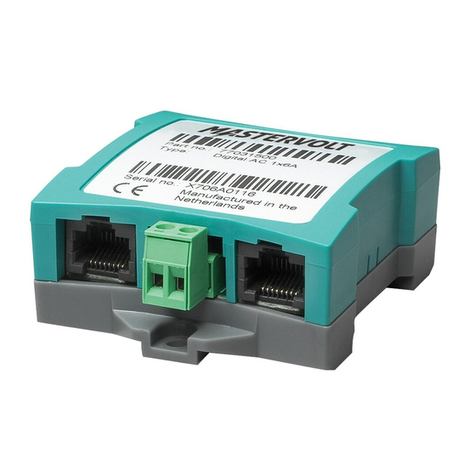
Mastervolt Digital AC 1x6A User manual

USERS MANUAL / GEBRUIKERSHANDLEIDING
BETRIEBSANLEITUNG / MANUEL D’UTILISATION
MANUAL DE UTILIZACION / INSTRUZIONI PER L’USO
Digital AC 1x6A
AC relay for digital switching
MASTERVOLT
Snijdersbergweg 93,
1105 AN Amsterdam
The Netherlands
Tel.: +31-20-3422100
Fax.: +31-20-6971006
mastervolt.com
ENGLISH: PAGE 1
NEDERLANDS: PAGINA 5
DEUTSCH: SEITE 9
FRANÇAIS: PAGINA 13
CASTELLANO: PÁGINA 17
ITALIANO: PÁGINA 21
MAS_TL_001_0211
Copyright © 2011 Mastervolt v 2.1 January 2011

2
1 GENERAL INFORMATION
1.1 Use of this manual
Copyright © 2011 Mastervolt. All rights reserved.
Reproduction, transfer, distribution or storage of part or
all of the contents in this document in any form without
the prior written permission of Mastervolt is prohibited.
This manual serves as a guideline for the safe and
effective operation of the Digital AC 1x6A.
Keep this manual at a secure place!
1.2 Guarantee specications
Mastervolt guarantees that this product was built
according to the legally applicable standards and
stipulations. If you fail to act in accordance with the
regulations, instructions and stipulations in this user’s
manual, damage can occur and/or the product will
not full the specications. This may mean that the
guarantee will become null and void.
IMPORTANT: The standard guarantee period is two
years after date of purchase.
1.3 Liability
Mastervolt can accept no liability for:
• Consequential damage due to use of the Digital AC
1x6A;
• Possible errors in the manuals and their results;
• Use that is inconsistent with the purpose of the
product.
CAUTION!
Never remove the identication label.
2 OPERATION
2.1 MasterBus functions
The Digital AC 1x6A operation is entirely MasterBus
based. See www.mastervolt.com for information about
MasterBus and the MasterBus event structure. The
table below shows the relay functions.
Monitoring Description Default Range
State Relay can be switched On (active) or Standby Standby Standby / Active
Control Change the state of the relay Standby Active / Standby
Conguration
General
Language Set the MasterBus Digital AC menu language English See specications
Device name Any name you wish with 12 characters max AC Relay 12 characters max
Event locked Check box for installers to lock event conguration.
Only operable by installers.
Unchecked Unchecked / Checked
Conguration Timing
Min. runtime Check box to enable the function Minimum runtime
for switching the relay.
Unchecked Unchecked / Checked
Min. runtime Minimum runtime setting 15 minutes 1-65535 minutes
Max. runtime Check box to enable the function Maximum runtime
for relay switching the relay.
Unchecked Unchecked / Checked
Max. runtime Maximum runtime setting 480 minutes 1-65535 minutes
Event commands
Activate The Digital AC 1x6A can be switched On (activate)
or Standby.
— —
MPC stop MPC (Maximum Power Control) prevents a power
source from being overloaded. At MPC stop the AC
1x6A disconnects the load.
— —
MPC reduce At the end of MPC reduce the AC 1x6A reconnects
the load.
— —
January 2011 / Digital AC 1x6A / EN

3
3 INSTALLATION
3.1 Overview
Insert the MasterBus cables, then connect the relay
cables to the screw terminal input and output, see below.
Functional scheme of the Digital AC 1x6A
3.2 Installation schemes
The Digital AC 1x6A is suitable for switching AC currents
up to 6A. For currents above 6A you need an external
relay which is controlled by the AC 1x6A.
You also need to add a fuse like shown for
load protection.
1. Input
2. Output (normally open)
3. Communication LED, illuminating when the
state is “activate” MasterBus connector
Function:
Standby: Relay is open,
Activate: 1 is connected to 2,
Maximum relay current: 6A
External relay
Installation schemes for currents up to 6A and above
EN / Digital AC 1x6A / January 2011

4 SPECIFICATIONS
Model: Digital AC 1x6A
Article number: 77031500
Delivery also includes: Screw terminal, MasterBus cable, MasterBus Terminating device, User’s manual
Function of instrument: MasterBus controlled AC relay
Potential free contact: 1:C, 2:NO – 6A / 230 V AC
Languages available: English,Nederlands,Deutsch,Français,Castellano,Italiano,Norsk,Svenska,Suomi,Dansk
Power consumption: 132 mW
MasterBus Powering: No
Din rail mounting: Yes, Din rail 30 mm [1.2 inch]
Protection degree: IP 21
Dimensions: 66 x 78 x 32 mm [2.6 x 3.1 x 1.3 inch]; see drawing below
Weight: Approx. 80 gr [0.18 lb]
5 EC DECLARATION OF CONFORMITY
This product is in conformity with the provision of the EC EMC directive 89/336/EEC and amendments 92/31/EEC,
93/68/EEC. Standards applied:
Generic emission standard: EN 50081-1:1992,
Generic Immunity standard: EN 50082-1:1997,
Safety directive 2006/95/EC, with the following standard,
Low voltage standard: EN 60950: 2000.
=
Dimensions in mm (inch) and connections
MasterBus
connector
Screw terminal
Snijdersbergweg 93, 1105 AN Amsterdam, The Netherlands
Tel: +31-20-3422100 • Fax: +31-20-6971006
Email: [email protected]

USERS MANUAL / GEBRUIKERSHANDLEIDING
BETRIEBSANLEITUNG / MANUEL D’UTILISATION
MANUAL DE UTILIZACION / INSTRUZIONI PER L’USO
Digital AC 1x6A
AC relais voor digitaal schakelen
MASTERVOLT
Snijdersbergweg 93,
1105 AN Amsterdam
The Netherlands
Tel.: +31-20-3422100
Fax.: +31-20-6971006
mastervolt.com
ENGLISH: PAGE 1
NEDERLANDS: PAGINA 5
DEUTSCH: SEITE 9
FRANÇAIS: PAGINA 13
CASTELLANO: PÁGINA 17
ITALIANO: PÁGINA 21
MAS_TL_001_0211
Copyright © 2011 Mastervolt v 2.1 January 2011

6
1 ALGEMENE INFORMATIE
1.1 Gebruik van deze handleiding
Copyright © 2011 Mastervolt. Alle rechten voorbehouden.
Onrechtmatige reproductie, overdracht, distributie
of opslag van dit document of een gedeelte ervan
in enige vorm zonder voorafgaande geschreven
toestemming van Mastervolt is verboden.
Deze handleiding dient als richtlijn om de Digital AC
1x6A op een veilige en doelmatige wijze te bedienen.
Bewaar deze handleiding op een veilige plaats!
1.2 Garantiebepalingen
Mastervolt garandeert dat het apparaat is gebouwd
volgens de wettelijk van toepassing zijnde normen
en bepalingen. Wanneer niet volgens de in deze
gebruikershandleiding gegeven voorschriften,
aanwijzingen en bepalingen wordt gehandeld, kunnen
beschadigingen ontstaan en/of het apparaat zal
niet aan de specicaties voldoen. Eén en ander kan
inhouden dat de garantie komt te vervallen.
1.3 Aansprakelijkheid
Mastervolt stelt zich niet aansprakelijk voor:
• gevolgschade ontstaan door het gebruik van de
Digital AC 1x6A;
• eventuele fouten in bijbehorende handleidingen en de
gevolgen daarvan.
• gebruik dat niet overeenkomt met de bestemming van
dit produkt.
LET OP!
Verwijder nooit de typenummerplaat!
2 BEDIENING
2.1 MasterBusfuncties
De bediening van de Digital AC 1x6A is volledig
op MasterBus gebaseerd. Zie www.mastervolt.
com voor meer informatie over MasterBus en de
MasterBus eventopbouw. De tabel hieronder toont de
relaisfuncties.
Monitoring Omschrijving Default Bereik
Status Relais kan worden ingeschakeld (Geactiveerd) of
op Standby worden gezet.
Standby Standby/ Geactiveerd
Bediening Verander de status van het relais. Standby Geactiveerd/ Standby
Algemene
conguratie
Taal Stel de menutaal in van de Digital AC. English Zie specicaties
Apparaatnaam Elke naam met maximaal 12 karakters. Digital AC Maximaal 12 karakters
Events geblok. Check box voor installateurs om de
eventconguratie te vergendelen. Alleen voor
installateurs.
Niet
aangevinkt
Niet aangevinkt /
aangevinkt
Conguratie Timing
Min. looptijd Check box om de functie Minimum runtime in te
schakelen.
Niet
aangevinkt
Niet aangevinkt /
aangevinkt
Min. looptijd Minimum runtime instelling 15 minuten 1-65535 minuten
Max looptijd Check box om de functie Maximum runtime in te
schakelen.
Niet
aangevinkt
Niet aangevinkt /
aangevinkt
Max looptijd Maximum runtime instelling 480 minuten 1-65535 minuten
Event commando’s
Activeren De Digital AC 1x6A kan worden ingeschakeld
(Geactiveerd) of op Standby worden gezet.
— —
MPC stop MPC (Maximum Power Control) voorkomt
overbelasting van een energiebron. Bij MPC stop
ontkoppelt de AC 1x6A de last.
— —
MPC verminder Na MPC reduce koppelt de AC 1x6A de last weer. — —
January 2011 / Digital AC 1x6A / NL

7
3 INSTALLATIE
3.1 Overzicht
Steek de MasterBus kabels in de connectoren, verbind
daarna de relaiskabels met de in- en uitgang van de
schroefaansluiting, zie hieronder.
Functioneel schema van een Digital AC 1x6A
3.2 Installatieschema’s
De Digital AC 1x6A is geschikt om AC stroomsterktes tot
6A te schakelen. Voor hogere stroomsterktes heeft u een
extern relais nodig dat met de AC 1x6A wordt bediend.
Verder heeft u een zekering nodig zoals in de
illustratie, om de last te beveiligen.
1. Ingang
2. Uitgang (normally open)
3. Com municatieLED, licht op als de staat
“Geactiveerd” is. MasterBusconnector
Functie:
Standby: Relais is open,
Geactiveerd: 1 is verbonden met 2,
Maximale relaisstoom: 6A
Extern relais
Installatieschema’s tot aan 6A en daarboven
NL / Digital AC 1x6A / January 2011

4 SPECIFICATIES
Model: Digital AC 1x6A
Artikelnummer: 77031500
Meegeleverd: Schroefaansluiting, MasterBuskabel, MasterBus Terminator, Gebruikershandleiding
Functie: Via MasterBus bediend AC relais
Potentiaalvrij contact: 1:C, 2:NO – 6A / 230 V AC
Beschikbare talen: English,Nederlands,Deutsch,Français,Castellano,Italiano,Norsk,Svenska,Suomi,Dansk
Energieverbruik: 132 mW
MasterBus voedend: Nee
Din rail montage: Ja, Din rail 30 mm [1.2 inch]
Beschermingsgraad: IP 21
Afmetingen: 66 x 78 x 32 mm [2.6 x 3.1 x 1.3 inch]; zie tekening hieronder
Massa: Circa 80 g [0.18 lb]
5 EG VERKLARING VAN OVEREENKOMST
Dit product voldoet aan de bepalingen van de EC EMC richtlijn 89/336/EEC en amendementen 92/31/EEC, 93/68/EEC.
Toegepaste geharmoniseerde normen:
Emmissie: EN 50081-1:1992, Immuniteit: EN 50082-1:1997,
Laagspanningsrichtlijn 2006/95/EC, met standaard:
Veiligheid: EN 60950: 2000.
=
Dimensions in mm (inch) and connections
MasterBus
connector
Screw terminal
Snijdersbergweg 93, 1105 AN Amsterdam, The Netherlands
Tel: +31-20-3422100 • Fax: +31-20-6971006
Email: [email protected]

USERS MANUAL / GEBRUIKERSHANDLEIDING
BETRIEBSANLEITUNG / MANUEL D’UTILISATION
MANUAL DE UTILIZACION / INSTRUZIONI PER L’USO
Digital AC 1x6A
AC-Relais für digitales Schalten
MASTERVOLT
Snijdersbergweg 93,
1105 AN Amsterdam
The Netherlands
Tel.: +31-20-3422100
Fax.: +31-20-6971006
mastervolt.com
ENGLISH: PAGE 1
NEDERLANDS: PAGINA 5
DEUTSCH: SEITE 9
FRANÇAIS: PAGINA 13
CASTELLANO: PÁGINA 17
ITALIANO: PÁGINA 21
MAS_TL_001_0211
Copyright © 2011 Mastervolt v 2.1 January 2011

10
1 ALLGEMEINE INFORMATIONEN
1.1 Verwendung dieses Handbuchs
Copyright © 2011 Mastervolt. Alle Rechte vorbehalten.
Der Inhalt dieses Dokuments darf ohne vorherige
schriftliche Zustimmung durch Mastervolt in keiner
Form, weder ganz noch teilweise, vervielfältigt,
weitergegeben, verbreitet oder gespeichert werden.
Diese Betriebsanleitung dient als Richtlinie für einen
sicheren und reibungslosen Einsatz des Digital AC 1x6A.
Bewahren Sie diese Anleitung an einem sicheren Ort auf!
1.2 Garantiespezikationen
Mastervolt garantiert, dass dieses Produkt gemäß
den gesetzlich gültigen Normen und Bestimmungen
hergestellt wurde. Wenn Sie die Vorschriften,
Anweisungen und Bestimmungen in dieser
Betriebsanleitung nicht einhalten, können Schäden
verursacht werden und/oder das Produkt stimmt nicht
mehr mit den Spezikationen überein. Das kann dazu
führen, dass die Garantie verfällt.
WICHTIG: Die Standard-Gewährleistungsfrist beträgt
zwei Jahre nach Kaufdatum.
1.3 Haftung
Mastervolt übernimmt keine Haftung für:
• Folgeschäden die aus dem Gebrauch des Digital AC
1x6A entstehen;
• Mögliche Fehler in den Handbüchern und daraus
resultierende Konsequenzen;
• Nutzung die dem Zweck des Produktes nicht entspricht.
ACHTUNG!
Niemals die CE-Kennzeichnung entfernen.
2 BETRIEB
2.1 MasterBus-Funktionen
Der Betrieb des Digital AC 1x6A basiert vollständig auf
den MasterBus. Informationen über den MasterBus
sowie die Ereignisstruktur des MasterBus erhalten Sie
unter www.mastervolt.com. In der folgenden Tabelle
sind die Relaisfunktionen aufgeführt.
Überwachung Beschreibung
Einstellung
ab Werk Spektrum
Status Relais kann auf Ein (aktivieren) oder auf Standby
geschaltet werden
Standby Standby / Aktivieren
Bedienung Relaisstatus ändern Standby Aktivieren / Standby
Konguration
Allgemein
Sprache Einstellen der Menüsprache des MasterBus Digital
AC
English Siehe
Spezikationen
Gerätename Jeder gewünschte Name mit maximal 12 Zeichen AC-Relais Max. 12 Zeichen
Ergns gesperrt Option für Installateure zur Sperrung der
Ereigniskonguration. Nur von Installateuren durchführbar
Aus Aus / Ein
Konguration Timing
Minimum Laufzeit Option für eine Mindestlaufzeit Aus Aus / Ein
Minimum Laufzeit Einstellung der Mindestlaufzeit 15 Minuten 1-65535 Minuten
Maximum Laufzeit Option für eine maximale Laufzeit Aus Aus/Ein
Maximum Laufzeit Einstellung der maximalen Laufzeit 480 Minuten 1-65535 Minuten
Ereignisbefehle
Aktivieren Das Digital AC 1x6A kann auf Ein (aktivieren) oder
auf Standby geschaltet werden
— —
MPC halt Der Spannungsbegrenzer verhindert die Überlastung
einer Leistungsquelle. Bei MPC stop schaltet das AC
1x6A die Last ab.
— —
MPC reduzier Bei Erreichen der minimal eingestellten
Spannungshöhe schaltet das AC 1x6A die Last
wieder ein.
— —
January 2011 / Digital AC 1x6A / DE
11
3 INSTALLATION
3.1 Übersicht
Setzen Sie die MasterBus-Kabel ein, schließen Sie
dann die Relais-Kabel an den Eingang und den
Ausgang der Schraubklemme gemäß Abbildung weiter
unten an.
Funktionsschema des Digital AC 1x6A
3.2 Installationsschema
Das Digital AC 1x6A ist zum Schalten von
Wechselströmen bis zu 6A geeignet. Für Ströme über
6A ist ein externes Relais erforderlich, das vom AC 1x6A
angesteuert wird.
Auch muss - wie angegeben - eine
Sicherung für den Lastschutz angebracht
werden.
1. Eingang
2. Ausgang (normal offen)
3. Kommunikations-LED, leuchtet, wenn der
Status “MaterBus-Anschluss aktiv” ansteht
Funktion:
Bereitschaft: Relaiskontakt ist offen
Aktiv: 1 ist mit 2 verbunden
Max. Relaisstrom: 6 A
Externe relais
Installationsschema für Ströme bis 6A und darüber
DE / Digital AC 1x6A / January 2011

4 SPEZIFIKATIONEN
Modell: Digital AC 1x6A
Artikelnummer: 77031500
Mitgeliefert: Schraubklemme, MasterBus-Kabel, MasterBus-Abschlussvorrichtung, Betriebsanleitung
Funktion des Gerätes: Durch MasterBus kontrolliertes AC-Relais
Potenzialfreier Kontakt: 1:C, 2:NO – 6A / 230 V AC
Verfügbare Sprachen: English, Nederlands, Deutsch, Français, Castellano, Italiano, Norsk, Svenska, Suomi,
Dansk
Stromverbrauch: 132 mW
MasterBus Powering: Nein
Din-Schienen-Montage: Ja, Din-Schiene 30 mm [1,2 Inch]
Schutzgrad: IP 21
Abmessungen: 66 x 78 x 32 mm [2,6 x 3,1 x 1,3 Inch]; siehe Zeichnung weiter unten
Gewicht: Ca. 80 gr [0,18 lb]
5 EG-KONFORMITÄTSERKLÄRUNG
Dieses Produkt stimmt überein mit der Bestimmung der EMV-Richtlinie 89/336/EEC der EG und den Ergänzungen
92/31/EEC, 93/68/EEC. Es wurden folgende harmonisierten Normen zugrunde gelegt:
Generische Emissionsnorm: EN 50081-1:1992
Generische Immunitätsnorm: EN 50082-1:1997
Sicherheitsrichtlinie 2006/95/EC, mit folgender Norm:
Niederspannungsrichtlinie: EN 60950: 2000
=
Abmessungen in mm (Zoll) und Anschlüsse
MasterBus-Anschluss
Schraubklemme
Snijdersbergweg 93, 1105 AN Amsterdam, The Netherlands
Tel: +31-20-3422100 • Fax: +31-20-6971006
Email: [email protected]

USERS MANUAL / GEBRUIKERSHANDLEIDING
BETRIEBSANLEITUNG / MANUEL D’UTILISATION
MANUAL DE UTILIZACION / INSTRUZIONI PER L’USO
Digital AC 1x6A
Relais AC pour commutation numérique
MASTERVOLT
Snijdersbergweg 93,
1105 AN Amsterdam
The Netherlands
Tel.: +31-20-3422100
Fax.: +31-20-6971006
mastervolt.com
ENGLISH: PAGE 1
NEDERLANDS: PAGINA 5
DEUTSCH: SEITE 9
FRANÇAIS: PAGINA 13
CASTELLANO: PÁGINA 17
ITALIANO: PÁGINA 21
MAS_TL_001_0211
Copyright © 2011 Mastervolt v 2.1 January 2011

14
1 INFORMATION GÉNÉRALE
1.1 Utilisation de ce manuel
Copyright © 2011 Mastervolt. Tous droits réservés.
La reproduction, le transfert, la distribution ou
l’entreposage d’une partie ou du contenu en entier
de ce document sous toute forme que ce soit sans la
permission préalable écrite de Mastervolt est interdit.
Ce manuel sert de guide pour une opération sécuritaire
et efcace du Digital AC 1x6A.
Conserver ce manuel dans un endroit sécuritaire!
1.2 Spécications de la garantie
Mastervolt garantit que ce produit a été construit selon
les normes et les stipulations légalement applicables.
Si vous ne vous conformez pas aux règlements,
instructions et stipulations dans ce manuel de
l’utilisateur, des dommages peuvent s’ensuivre et/ou
le produit ne répondra pas aux spécications. Ce qui
pourrait signier que la garantie est nulle et non avenue.
IMPORTANT : La période normale de garantie est de
deux ans après la date d’achat.
1.3 Responsabilité
Mastervolt ne peut accepter aucune responsabilité pour :
• les dommages indirects causés par l’utilisation du
Digital AC 1x6A;
• les erreurs possibles dans les manuels et leurs résultats;
• une utilisation qui n’est pas compatible avec l’usage
visé de ce produit.
PRUDENCE!
N’enlevez jamais l’étiquette d’identication.
2 OPÉRATION
2.1 Fonctions du MasterBus
L’opération du Digital AC 1x6A est basée
complètement sur le MasterBus. Voir www.mastervolt.
com pour des informations au sujet de MasterBus et de
la structure d’événements de MasterBus. Le tableau
ci-dessous illustre les fonctions du relais.
Surveillance Description Default Range
Statut Le relais peut être mis à On (activé) ou en Attente Standby Standby / Activate
Controle Changer l’état du relais Standby Activate / Standby
Conguration générale
Langue Régler la langue du menu MasterBus Digital AC English See specications
Nom d’appareil N’importe quel nom qui contient 12 caractères max AC Relay 12 characters max
Verr. evnmt Cocher la case pour que les installateurs
verrouillent la conguration de l’événement. Peut
être mis en action uniquement par les installateurs
Unchecked Unchecked /
Checked
Timing de la
Conguration
Tps fonct min. Cocher la case pour activer la fonction Durée
d’exécution minimum pour commuter le relais.
Unchecked Unchecked /
Checked
Tps fonct min. Réglage de la Durée d’exécution minimale. 15 minutes 1-65535 minutes
Tps fonct max. Cocher la case pour activer la fonction Durée
d’exécution maximale pour commuter le relais.
Unchecked Unchecked /
Checked
Tps fonct max. Réglage de la Durée d’exécution maximale. 480 minutes 1-65535 minutes
Commandes
d’événements
Activer Le Digital AC 1x6A peut être mis à On (activé) ou
en Attente.
— —
MPC arrêt Le MPC (Commande de Puissance Maximale)
empêche une source d’alimentation d’être
surchargée. À l’arrêt du MPC le AC 1x6A
déconnecte la charge.
— —
MPC reduis À la n de la réduction du MPC le AC 1x6A
reconnecte la charge.
— —
January 2011 / Digital AC 1x6A / FR

15
3 INSTALLATION
3.1 Aperçu
Insérez les câbles MasterBus, puis connectez les
câbles du relais aux bornes à vis d’entrée et de sortie,
voir ci-dessous.
Plan fonctionnel du Digital AC 1x6A
3.2 Plans d’installation
Le Digital AC 1x6A est approprié pour commuter des
courants AC jusqu’à 6A. Pour les courants au dessus
de 6A vous avez besoin d’un relais externe qui est
contrôlé par le AC 1x6A.
Vous avez aussi besoin d’ajouter un fusible
tel qu’illustré pour une protection de charge.
1. Entrée
2. Sortie (normalement fermée)
3. DEL de communication, illuminé lorsque l’état
du connecteur MasterBus est « activé »
Fonction :
En attente : le relais est ouvert,
Activé : 1 est connecté à 2,
Courant maximum du relais : 6 A
Relais externe
Plans d’installation pour les courants jusqu’à 6A et au dessus
FR / Digital AC 1x6A / January 2011

4 SPÉCIFICATIONS
Modèle : Digital AC 1x6A
Numéro d’article : 77031500
La livraison inclut aussi : Borne à vis, Câble MasterBus, Dispositif de terminaison MasterBus, Manuel de
l’utilisateur
Fonction de l’instrument : Relais AC contrôlé par MasterBus
Contact gratuit possible : 1:C, 2:NO – 6A / 230 V AC
Langues disponibles : English,Nederlands,Deutsch,Français,Castellano,Italiano,Norsk,Svenska,Suomi,Dansk
Consommation de courant : 132 mW
Alimentation du MasterBus : Non
Assemblage du rail DIN : Oui, rail DIN 30 mm [1,2 pouces]
Degré de protection : IP 21
Dimensions : 66 x 78 x 32 mm [2,6 x 3,1 x 1,3 pouces]; voir croquis ci-dessous
Poids : Approx. 80 gr [0,18 lb]
5 DÉCLARATION DE CONFORMITÉ CE
Ce produit est conforme à la provision de la directive CE CEM 89/336/CEE et aux amendements 92/31/CEE, 93/68/
CEE. Normes appliquées :
Generic emission standard : EN 50081-1:1992,
Generic Immunity standard : EN 50082-1:1997,
Directive de sécurité 2006/95/CE, avec la norme suivante,
Low voltage standard : EN 60950 : 2000.
=
Dimensions en mm (pouce) et connexions
Connecteur
MasterBus
Borne à vis
Snijdersbergweg 93, 1105 AN Amsterdam, The Netherlands
Tel: +31-20-3422100 • Fax: +31-20-6971006
Email: [email protected]

USERS MANUAL / GEBRUIKERSHANDLEIDING
BETRIEBSANLEITUNG / MANUEL D’UTILISATION
MANUAL DE UTILIZACION / INSTRUZIONI PER L’USO
Digital AC 1x6A
Relé AC para conmutación digital
MASTERVOLT
Snijdersbergweg 93,
1105 AN Amsterdam
The Netherlands
Tel.: +31-20-3422100
Fax.: +31-20-6971006
mastervolt.com
ENGLISH: PAGE 1
NEDERLANDS: PAGINA 5
DEUTSCH: SEITE 9
FRANÇAIS: PAGINA 13
CASTELLANO: PÁGINA 17
ITALIANO: PÁGINA 21
MAS_TL_001_0211
Copyright © 2011 Mastervolt v 2.1 January 2011

18
1 INFORMACIÓN GENERAL
1.1 Uso di questo manuale
Copyright © 2011 Mastervolt. Todos los derechos reservados.
Se prohíbe la reproducción, transferencia, distribución
o almacenaje de una parte o el total del contenido
de este documento, en cualquier forma, sin premiso
previo por escrito de Mastervolt.
Este manual sirve de guía para la operación segura y
ecaz del Digital AC 1x6A.
¡Conserve este manual en un lugar seguro!
1.2 Especicaciones de la garantía
Mastervolt garantiza que este producto fue construido
de acuerdo con normas y estipulaciones legalmente
aplicables. Si usted no actúa de acuerdo con las
normas, instrucciones y estipulaciones en este manual
de utilización, pueden ocurrir daños y/o el producto
puede no cumplir con las especicaciones. Esto puede
signicar que la garantía quedará sin efecto y nula.
IMPORTANTE: El periodo estándar de la garantía es
de dos años a partir de la fecha de compra.
1.3 Responsabilidad
Mastervolt no asume responsabilidad por:
• daños consecuenciales debido al uso del
Digital AC 1x6A;
• posibles errores en los manuales y sus resultados;
• Use que sea incompatible con la nalidad del
producto.
¡CUIDADO!
Nunca retire la etiqueta de identicación.
2 FUNCIONAMIENTO
2.1 Funciones del MasterBus
El funcionamiento del Digital AC 1x6A está
enteramente basado en el MasterBus. Vea
www.mastervolt.com para obtener información sobre el
MasterBus y la estructura de eventos del MasterBus. El
cuadro a continuación muestra las funciones del relé.
Monitoreo Descripción Pre
congurado
Rango
Estado Se puede encender (activar) el relé o se lo puede
poner en espera (Standby)
Standby Standby/
Activar
Control Cambio del estado del relé Standby Activar/ Standby
Conguración General
Lengua Congurar el idioma del menú del MasterBus Digital AC Inglés
Ver
especicaciones
Nombre disp. Cualquier nombre que desee con un máx. de 12
caracteres
Relé AC Máx. de 12
caracteres
Eventos bloq. Marque la casilla para que los instaladores bloqueen la
conguración de eventos. Solo operable por instaladores.
Sin marcar Sin marcar/
Marcado
Conguración Temporización
Min Tiempo act. Marque la casilla para permitir la función de tiempo de
funcionamiento Mínimo para la conmutación del relé.
Sin marcar Sin marcar/
Marcado
Min Tiempo act. Ajuste del tiempo de funcionamiento mínimo 15 minutos 1-65535
minutos
Max tiemp act. Marque la casilla para permitir la función de tiempo de
funcionamiento Máximo para la conmutación del relé.
Sin marcar Sin marcar/
Marcado
Max tiemp act. Ajuste de tiempo de funcionamiento máximo 480 minutos
1-65535 minutos
Comandos de eventos
Activar Se puede encender (activar) el Digital AC 1x6A o se lo
puede poner en espera (Standby).
— —
MPC parar El Control de Potencia Máxima (MPC -Maximum
Power Control) evita que una fuente de energía sea
objeto de sobrecarga. En parada de MPC, el AC 1x6A
desconecta la carga.
— —
MPC reduce Al nal de la reducción de MPC, el AC 1x6A reconecta
la carga.
— —
January 2011 / Digital AC 1x6A / CA

19
3 INSTALACIÓN
3.1 Reseña General
Inserte los cables del MasterBus, luego conecte los
cables de relé a la entrada y salida de terminal de
tornillo; ver a continuación.
Diagrama funcional del Digital AC 1x6A
3.2 Diagramas de instalación
El Digital AC 1x6A es apto para la conmutación de
corrientes CA hasta 6A. Para corrientes superiores a 6A
se necesita un relé externo controlado por el AC 1x6A.
También se necesita agregar un fusible, como se
ilustra, para protección de carga.
1. Ingresso
2. Uscita (normalmente aperta)
3. LED di comunicazione, si illumina quando lo
stato è connettore MasterBus “attivato”
Funzione:
Standby: relè aperto,
Attivato: 1 è collegato a 2,
Massima corrente relè: 6A
Relè esterno
Diagramas de instalación para corrientes de hasta 6A o más
CA / Digital AC 1x6A / January 2011

4 ESPECIFICACIONES
Modelo: Digital AC 1x6A
Número de artículo: 77031500
El envío también incluye: Terminal de tornillo, cable de MasterBus, dispositivo de terminación del MasterBus,
Manual de Utilización
Función del instrumento: Relé CA controlado por el MasterBus
Contacto libre potencial: 1:C, 2:NO – 6A / 230 V CA
Idiomas disponibles: English,Nederlands,Deutsch,Français,Castellano,Italiano,Norsk,Svenska,Suomi,Dansk
Consumo de energía: 132 mW
Activación del MasterBus: No
Montaje en riel Din: Sí, riel Din de 30 mm [1-2 pulgadas]
Grado de protección: IP 21
Dimensiones: 66 x 78 x 32 mm [2.6 x 3.1 x 1.3 pulgadas]; ver diagrama a continuación
Peso: Aprox. 80 gr. [0.18 lb]
5 EC DECLARACIÓN DE CONFORMIDAD
Este producto es compatible con la disposición de la directiva EC EMC 89/336/EEC y enmiendas 92/31/EEC, 93/68/
EEC. Normas aplicadas:
Estándar de emisión genérico: EN 50081-1:1992,
Estándar de Inmunidad Genérico: EN 50082-1:1997,
Directiva de seguridad 2006/95/EC, con el siguiente estándar,
Estándar de baja tensión: EN 60950: 2000.
=
Dimensiones en mm (pulgadas) y conexiones
Conector
MasterBus
Atornillar terminal
Snijdersbergweg 93, 1105 AN Amsterdam, The Netherlands
Tel: +31-20-3422100 • Fax: +31-20-6971006
Email: [email protected]
Other manuals for Digital AC 1x6A
2
This manual suits for next models
1
Table of contents
Languages:
Other Mastervolt Relay manuals

Mastervolt
Mastervolt Charge Mate Pro 40 User manual

Mastervolt
Mastervolt 77030500 User manual

Mastervolt
Mastervolt Multipurpose Contact Output Operating manual

Mastervolt
Mastervolt Digital AC 1x6A Operating manual

Mastervolt
Mastervolt Digital AC 1x6A User manual

Mastervolt
Mastervolt MLI Ultra Series Instruction Manual